
Introduction
Our project was to create two individual microcontrollers that can play banjo notes cooperatively to play two-part songs using nothing but sound to communicate and synchronize.
Humans have had the ability to synchronize musical instruments together to achieve a single, coordinated multi-part song for thousands of years. In our project we attempted to simulate the necessary communication and timing aspects needed to play musical instruments in a group using two independent microcontrollers. In order to accomplish this task, three main goals needed to be met. First, we needed a way to allow each microcontroller to tell when its partner emits sound. Second, a communication protocol needed to be established so that the two units could agree on what song to play and when to start. Third, we needed to create a method for digitally synthesizing a banjo waveform and then outputting an analog signal to speakers. With these core functionalities, we were able to construct a simple system that replicated the fundamental communication and synchronization needed to play music together.
High Level Design
Motivation
We were initially intrigued by a project idea posted on the course web page that involved several independent microcontrollers emitting random yet synchronized ultrasound bursts. We really liked the idea of coordinating independent nodes of a network in real time, and working together to accomplish a common goal. We then thought it would be interesting if we were able to apply the nodal synchronization to music. With some help from Morgan, our TA, and from the dueling banjos scene in ‘Deliverance’ we ultimately came up with the idea to acoustically synchronize two microcontrollers to play (and duel with) banjo songs.
Background Math
Although this project does not require much complicated math, there was one major mathematical method that we used in our implementation: the Karplus-Strong Algorithm. The Karplus-Strong Algorithm is an algorithm that is able to digitally generate a clean and realistic acoustic sound. To generate a given string pluck, our implementation of KSA uses a fixed length shift register to represent a string. Values are then fed into the array and as they are shifted through the array, they simulate how a wave would traverse a string in the real world. The values at the end of the shift register are sampled and then are passed through a digital low pass filter, and reinserted into the beginning of the shift register. This method allows the values in the shift register to resonate, and the decreases due to the filter represent the physical losses in a real string.
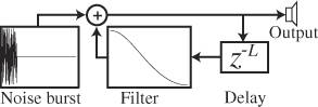
To vary the frequency of the notes generated by the KSA, only the size of the shift register needs to be changed. Since the values move through the shift register at the same speed as the sampling frequency, the resultant period of the signal is T = N*Ts, where N is the size of the shift register and Ts is the sampling period. This results in the equation F = Fs/N, where F is the frequency of the note being played, Fs is the sampling frequency and N is again the size of the array.
Structure
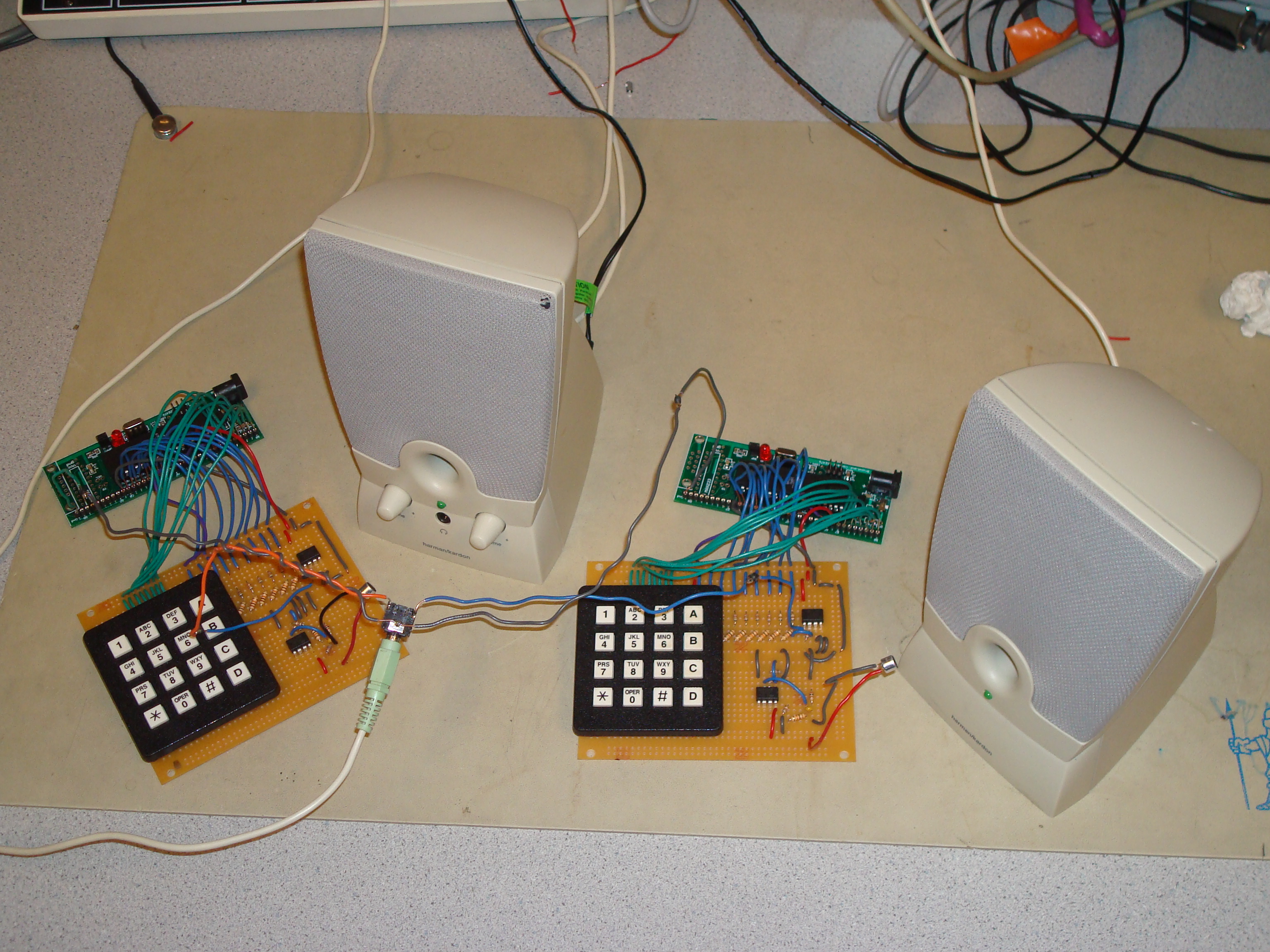
Our final project relies on the interaction of four major components. Each microcontroller samples the analog signal of a microphone circuit to get information on sounds in the environment. This raw data is then passed to the decode stage of our design. In the decoding stage, the microphone data is filtered and interpreted. Depending on the mode, this stage will either convert sequences of sinusoidal sound into bits or it will simply detect the pluck of a string. Once the input has been interpreted, this data is passed along to the digital sound synthesis stage. Depending on the mode, this stage will create an 8-bit representation of either a sinusoidal signal or it will generate a banjo waveform with by applying the Karplus-Strong Algorithm. This synthesized 8-bit representation is then passed into the sound generation stage. This stage consists of a simple resistor based digital to analog converter, which turns the digital output into a single analog voltage that is then applied to the input of a speaker. By following this structure, we are able to manipulate the sound output of each microcontroller based on what sounds the microphone registers.
Copyrighted Material
In order to realistically simulate the sound of a string instrument we used the Karplus-Strong Algorithm. The Karplus-Strong Algorithm was created by Kevin Karplus and Alex Strong and was first discussed in length in the paper
Kevin Karplus, Alex Strong (1983). "Digital Synthesis of Plucked String and Drum Timbres". Computer Music Journal 7 (2): 43-55. MIT Press.
The algorithm was patented by Kevin J. Karplus and Alexander R. Strong on March 17th, 1987 and assigned US Patent number 4,649,783.
Since our project revolves around music, we naturally wanted to program in some recognizable songs in addition to the songs that we wrote during the testing phase of our system. Although we got the notes for each of these songs off of free music tabs online, each of these songs are copyrighted and we have recognized each of the songs and artists below.
Cornell Alma Mater
Mary Had A Little Lamb
Dueling Banjos – Deliverance
Hardware Design
There were two main hardware components that needed to be constructed in order to accomplish our project goals. First, we needed to build a circuit that would allow us to sample usable analog data from a WM-65A103 microphone. Manipulating the microphone signal was essential since we found that simply hooking the microphone up in series with a resistor resulted in small variations of a DC biased voltage signal. These fluctuations were not large enough to be detected by the analog-to-digital converter, and thus failed to pass any necessary information to the microcontroller about the sound in the environment. Second, we needed to build a digital-to-analog converter circuit that could translate the 8-bit output set by the microcontroller at PORTC into an actual analog voltage that can be sent to a speaker system. We decided to use a DAC instead of using the PWM signal generation to create cleaner, better sounding audio.
In order to create an effective, reliable and sensitive microphone circuit, we needed to add several different components and stages. The first circuit design decision that was made was to make the voltage source equal to 5V. This was done for the simple reason that a reliable 5V source was readily available and this was well within the operating source voltage of the microphone. The MIC is then put in series with a 2k resistor. Since the microphone can be modeled as a variable resistor dependant on sound and pressure waves on the surface of the MIC, the total voltage drop across the 2k resistor will fluctuate depending on the sound at the MIC. Once the input sound at the microphone input has been translated into a fluctuating analog voltage, the signal is passed through a simple, first order high pass filter. This stage is necessary to eliminate the DC component of the signal and to reduce other prevalent low frequency ambient noise. The series capacitor was chosen to be 0.01 uF and the shunt resistor was set to be 110k. This results in a -3dB cutoff frequency of approximately fc = 1/(2πRC) = 144 Hz. This cutoff frequency was chosen so that it is high enough to filter out disruptive low frequency noise at 60 Hz but low enough that it is substantially below the lowest note that we intended to play at 261.61 Hz. The last and final stage of this circuit amplifies the AC signal so that it is large enough to achieve a reasonable level of granularity when passed through the digital-to-analog converter with a Vref = 5 V. To achieve approximate linear amplification, we made use of a single LM358 OPAMP, with a resistor R3 connecting the output to the negative feedback terminal and a resistor R4 between ground and the negative terminal. The gain of this amplifier is equal to G = (1 + R3/R4). The un-amplified audio signal was low enough that a gain of aproximately100 worked well to get the range of the signal to fluctuate between 0 V and 5 V. The values of R3 and R4 are taken as 100k and 1k respectively, resulting in a total gain of G=101. Although this is a high gain, and linearity is most likely not preserved, we decided that this was a reasonable trade-off, since we are simply trying to construct a circuit that can detect the presence of sound. The resulting circuit, as shown below, was able to reliably translate the presence of noise into a usable analog voltage signal. In practice, we found that this circuit was particularly well suited for our purpose, since it was reasonably sensitive to nearby sound but did not react much to ambient noise created a reasonable distance away. As a result, we were able to position the microphones near to the appropriate speakers, and were able to get a good enough signal to noise ratio to hear and distinguish between each note and sound emitted from the speakers.
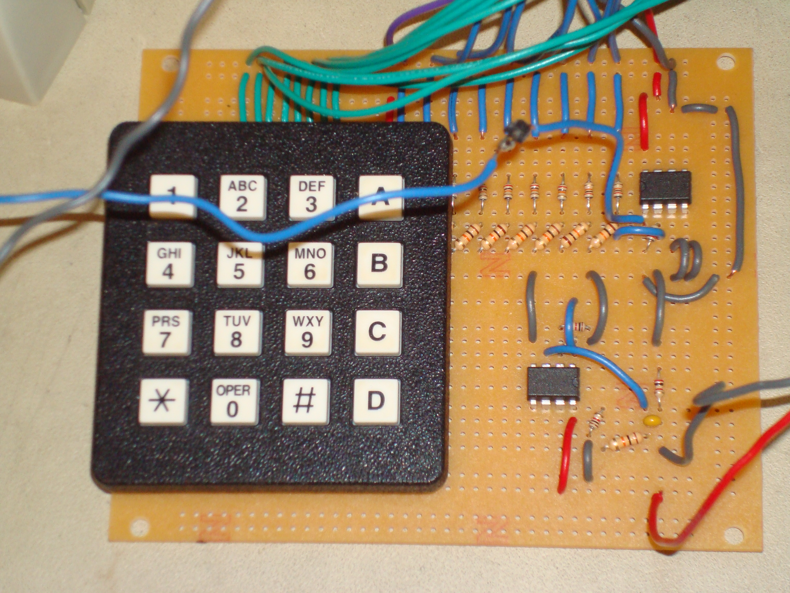
The second essential piece of hardware that our project relied on was a resistor based digital-to-analog converter. As our sound generation interrupt synthesized and output digital samples onto Port C, we needed to convert this into a usable analog signal. On the suggestion of our TA Morgan, we used a DAC instead of the built in PWM mode, with the intentions of getting a cleaner sound. We found a description and design of a DAC that used only 2 different resistor values (http://www.allaboutcircuits.com/vol_4/chpt_13/3.html) and we were able to easily create our own 8-bit replica as seen below. The fact that only two resistor values were needed was incredibly important due to the limited number of resistors available to us in lab. In order to ensure a high standard of accuracy, we measured each resistor used in our final soldered circuits to ensure that they were all within 2% of their intended values. We chose not to apply a low pass filter to the output of the DAC to filter out additional high frequency responses since we got a clear signal without the filter and we found that these high frequencies seemed to make our notes sound more banjo-like.
Software Design
High Level
The software design component of our project is fairly complex and consists of a very large state machine that controls the communication and song timing between the two nodes. This state machine can be broken down into two major tasks: Communication and Song Playing. The communication states deal with establishing a connection between two nodes and making sure that each node knows what song they are going to play. The song playing states deals with reading the song data, playing the notes at the proper time, and keeping track of notes played by the other node to ensure accurate timing between the two nodes. A general overview of how this state machine works is given below. The PLAY NOTE state and the LISTEN NOTE state make up the Song Playing part of the state machine, while the rest of the states make up the communication states.
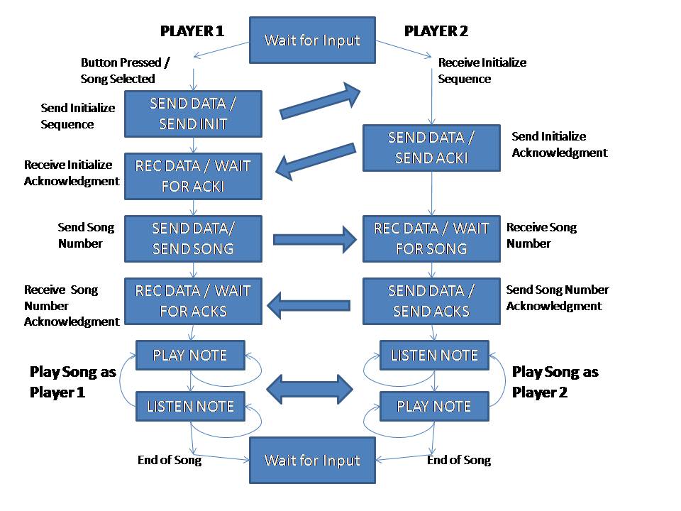
Originally both nodes start in the Wait for Input state where they wait for either a song to be selected on the keypad or an initialization sound sequence to be heard on the microphone. If a song is selected on the keypad of one of the nodes, that node identifies itself as player one and moves into the SEND DATA / SEND INIT state where it plays a series of eight sound pulses indicating to the other node that it wants to start playing a song. Player one then moves to REC DATA / WAIT FOR ACKI state where it waits to hear an acknowledgment to the initialization sequence it played. Upon hearing this initialization sequence, the other node identifies itself as player two, moves from the Wait for Input state to the SEND DATA /SEND ACKI state where it sends the same eight sound pulses back to player one as an acknowledgment. After sending this acknowledgment player two then moves to REC DATA / WAIT FOR SONG where it waits to hear what song they are going to play together.
Now back to player one, once it receives an acknowledgement from player two, it plays the eight pulse code for the song that they are going to play together in the SEND DATA/ SEND SONG state and waits for an acknowledgment from player two in the REC DATA / WAIT FOR ACKS state. Player two, upon receiving this song code, moves to the SEND DATA / SEND ACKS state and similar to before, plays back the same eight pulse code that it heard from player one as an acknowledgment. At this point Player two moves out of the last communication state into LISTEN NOTE, a song playing state, where it waits for player one to start playing the beginning of the song. Once player one receives this final acknowledgement, it moves into the PLAY NOTE state where it start playing the beginning of the song they agreed on.
At this point, player one will play all the notes that are assigned to it and move to the LISTEN NOTE state where it waits for player two to play all its notes. Once player two hears that player one has completed, it moves out of the LISTEN NOTE state and plays its own notes. After player two finishes all its notes, it moves back into the LISTEN NOTE state, while player one moves into the PLAY NOTE state. The two players continue to alternate between listening and playing like this until the song is complete. Once the song is complete both nodes return to the Wait for Input state, where both nodes are again waiting for an input and either node can be assigned as player one or player two.
This higher level explanation above describes exactly how our code operates, however many of the more technical details of how it operates are left out. Below we touch on some of the more interesting aspects of our code.
Communication States
Sound Debouncer
In order to communicate acoustically, we first needed to find a way to collect digital sound samples from the analog output of our microphone circuit. We accomplished this task by using the built in ADC with 8-bit accuracy. We sampled the signal at 2 kHz by collecting single sample every 0.5 ms, which was orchestrated by a 0.5 ms interrupt on Timer0. We chose to segment time into discrete units of 12.5 ms. Over this time period, we simply added up each of the 25 digital samples into the variable ‘sum’ to create a running tally of the total noise heard over the 12.5 ms interval. Once the 25th sample is collected, we were able to evaluate how much noise was present at the surface of the microphone during that instant in time. We created a threshold variable (set at 75) and we used this threshold to set a binary variable ‘temp’ that represented whether noise was present at the microphone. If the sum was less than the threshold, we set ‘temp’ equal to 0, and if the sum was greater than or equal to the threshold ‘temp’ was set to 1.
As a result of the above method for sampling and determining the presence of sound, we can consider the input of the microphone to be a string of binary digits with a new bit arriving every 12.5 ms. In order to have a functional communication state, we need to differentiate between random ambient noise spikes being registered on the microphone and intended sinusoidal noise pulses sent from the peer microcontroller. In order to keep our system from recognizing quick noise spikes as communication pulses, we use the temp variable as an input to a 6-state state machine. This is a very simple state machine that works very effectively to determine whether or not there is a continuous and intended pulse of noise being directed at the microphone. In order for a noise pulse to be recognized, three consecutive samples of ‘temp’ must have a value of 1. Symmetrically, if a noise pulse is currently being detected, it takes three consecutive samples of ‘temp’ being equal to 0 for the state machine to recognize the end of the noise pulse. It is with the use of this simple state machine that we are able to filter our digital input and determine whether or not the microphone is listening to a sound pulse.
In order to pass information acoustically, our two nodes simply choose the length of time that a sound pulses is sent in order to distinguish between a binary ‘1’ and ‘0’. In our case, a ‘0’ represents a pulse of 125 ms and a ‘1’ represents a sound pulse of 250 ms. In order to detect the length of each sound pulse we simply increment a counter ‘pulse_length’ for every 12.5 ms chunk of time that the state machine described above determines that there is sound present. Once the state machine determines that the pulse of sound has ended, the ‘pulse_length’ counter can be used to determine whether the sound pulse represented a ‘1’ or a ‘0’. This value is then stored in an input variable. Each instance of communication between the two microcontrollers was a sequential series of 8 sound pulses. After a microcontroller has received 8 pulses, it analyzes the new byte data it has received and is able to take appropriate action according to this information.
Using these methods of interpreting the analog input from the microphone, we are able to get the two microcontrollers to reliably pass data between the two nodes acoustically. This allows us to execute the initialization sequence and to send and receive song data as described above.
Keypad Debouncer
The Keypad debouncer for this lab is exactly analogous to the Keypad debouncer used in the other ECE 476 labs.
Song Playing
Song Encoding/Decoding
We encoded all of our songs in a 2D flash signed character array called songlist. Songlist is 11 by 240 array representing 11 playable songs each of potentially 240 notes. Each character represents a segment of 125 ms or 1/8 of a second with the 0th character of a song being the first 125ms segment and the 240th character being the last 125ms segment. If a character has a value between 1 and 25, then at the time segment corresponding to that character, player one plays a note. Depend on the value of the character, a different note is played. What each value corresponds to is given below.
Value Note
1 - C2
2 - C#2/Db2
3 - D2
4 - D#2/Eb2
5 - E2
6 - F2
7 - F#2/Gb2
8 - G2
9 - G#2/Ab2
10 - A2
11 - A#2/Bb2
12 - B2
13 - C3
14 - C#3/Db3
15 - D3
16 - D#3/Eb3
17 - E3
18 - F3
19 - F#3/Gb3
20 - G3
21 - G#3/Ab3
22 - A3
23 - A#3/Bb3
24 - B3
25 - C4
Similarly, if a character is a negative number between 1 and 25, then player two plays the corresponding note for that time segment. Also, if the character is zero, then no note is strummed. For example given the following sequence:
9,0,0,-11, 13,0,0,-11,
Player one starts playing G#/Ab at 0ms, player two starts playing A#/Bb at 375ms, player one starts playing C at 500ms, and finally player two starts playing A#/Bb again at the 875ms point. This kind of encoding is very similar to how regular music is written which allowed us to translate from sheet music to character array fairly easily.
We were able to integrate this song encoding into our music playing by simply keeping track of where we were in the song. While in the play state, at 125ms intervals, we check what the value of the current song index is. If the node is player one and the value is positive, it plays the note, and increments the song index. If the value is zero, the song index is again incremented but this time without playing any notes. Finally if the node is a note to be played by the other node, then this node knows that his play time is up and goes into the LISTEN NOTE state.
While in the LISTEN NOTE state, we had each node count the number of notes that the other node is supposed to play according to the song encodings. To do this, it iterates through the song array adding up the number of notes to be played by the other player until the current node hit one of its own notes. Once it hits its own note, the node stops counting and waits to hear the same number of notes as it had counted. Once the number of actual notes heard equals the number of expected notes, the node switches over to PLAY NOTE states and starts to play its notes.
To ensure we had accurate timing between nodes we had each node count the number of blank notes between the last note played by the other node and the first note to it be played by the current one. We then delayed playing the first note of the current node by 125ms multiplied by the number of blank notes. Finally the last thing we had to do to ensure accurate timing was to add an extra 87.5ms whenever we moved from the LISTEN NOTE state to the PLAY NOTE state. This must be done because when a node is in LISTEN NOTE state and registers a note, it always registers the note towards the beginning of the 125ms segment, due to how we indentify notes being played (see note identifier below). This is most easily seen when two back to back notes are supposed to be played. If we didn’t have this extra 87.5ms delay, then one player would start playing his note at the beginning of his 125ms segment. Then the other player would identify that a note is being played approximately 35ms in. If we didn’t have this extra delay the second player would start playing his note right away, instead of 125ms after the first player started playing his note. With this final addition we were able to make the timing between notes played by two different nodes indistinguishable to the timing between notes played by the same node.
Note Identifier
Although we already implemented a method for detecting noise pulses in the communication stage, we found that that was not an effective way to detect a note. This is because when multiple notes are strung together in quick secession, there is no guarantee that the communication state machine will fall out of the high state, and thus it would not always be able to distinguish between these notes. To solve this problem, and to gain a better ability to resolve notes, we created another state machine to detect the sharp rising edge of a note when it is played.
There are only three states in our note detection state machine: UP, DOWN and DELAY. In the UP state, the difference between the current sum and the previous sum is computed and compared to 0. If the difference is positive then we set a variable ‘total_rise’ equal to the positive difference and we jump into the DOWN state. In the down state we again compare the sum difference to 0. If it is greater than 0 we set ‘total_rise’ equal to the previous ‘total_rise’ plus the new sum difference, thereby accumulating the positive sum difference. If the sum difference is less than 0, then we compare ‘total_rise’ to some calibrated threshold. If the total positive edge is larger than this threshold, then we have detected a note and we jump into the DELAY state. If the ‘total_rise’ is less than the threshold, then it resets ‘total_rise’ to 0 and jumps back into UP. The state machine simply stays in DELAY for 4, 12.5 ms time chunks, and then returns to the UP state with ‘total_rise’=0. The purpose of the DELAY state is to avoid listening to the high amplitude noise on the decaying side of a loud note, since it is possible to register these fluctuations as additional notes. This DELAY in listening is acceptable, since the fastest that we play is 1 note per 0.125 seconds, and we could not reasonably expect another note for 10, 12.5 ms time chunks after a registered note.
Sound Generation – Karplus Strong Algorithm
We used two methods of sound generation for this project. To send the communication pulses, we used an accumulator and a sine table like we did in ECE 476 Lab 2 – DTMF Dialer. However for the Banjo sound generation we implemented the Karplus Strong Algorithm using a large character array as our shift register/delay line, and a very simple filter of adding the last two values on the shift register and multiplying it by .488 (or 0x007D in 8:8 fixed point). By multiplying by .488 instead of the typical .500, we were able to obtain a sharper decay on our string plucking sound making it more Banjo-like. Also we store many different shift register lengths so that we could get 25 different notes ranging 2 octaves. We experimented with these lengths and found that our current values produce the most realistic banjo sounds. This was all this was done at a sampling rate of 10 KHz and using the optimized fixed point multiply function found in the Fixed Point Math section of the ECE 476 website.
Results
Overall we were very pleased with the outcome of our project, and we feel that we successfully met our goals by demonstrating the principles of acoustic synchronization. Below is a video of our two
Our pair of MCUs were able to execute all of the necessary instructions in the allotted time, and as a result, there we no noticeable hesitations during the communication stage or while playing a song. For the most part, the user interface was very responsive and simple to use. Although it does not happen often, if a microphone detects some noise while a user attempts to input a song, the user is locked out until this noise has settled down. We felt that this was a reasonable trade off since if at any point a “player” hears an initialization request we would expect it to respond to that request rather than send its own initialization request.
We programmed each microcontroller to be able to play notes at up to 8 notes per second, which turns out to be one note every 0.125 seconds. When this maximum speed was measured with an oscilloscope, we found that our microcontrollers actually played at a maximum rate of 0.128 seconds, which is a 2.4 % error.
One of the main goals of our lab was to be able to achieve an unnoticeable time delay when the microcontrollers alternate playing notes. We were able to achieve an accuracy that could not be detected by (our) human ears. Upon further measurements, we found that the additional delay incurred from exchanging parts in a given song was only about 20 ms.
Our project posed very little danger to any user, since our project had no moving parts and only a simple keypad user interface. The user is not exposed to any high voltage or current lines since we used standard 9V DC power sources and there are no sharp edges on our solder boards. The only possible danger associated with our project is being rocked to death by some killer banjo tunes. Our project also posed very few interference problems with the projects of other groups, since our sound waves simply added to the ambient acoustic noise in the lab and did not interfere with an RF signals. We were aware, however, that other groups may have been annoyed by the repetitive testing of our communication protocols.
Conclusion
Expectations and Improvements
Our “Dueling Banjos” performed quite well, and met every one of our expectations. We were able to get two separate and completely symmetric (in both hardware and software) units to communicate and play preprogrammed songs together in a highly synchronized fashion. In addition to being able to properly synchronize the nodes in a given song, we were also able to produce what we found to be a reasonably accurate digital synthesis of banjo notes. We were able to produce and listen to these banjo notes fairly quickly, at a rate of about 8 notes per second, which exceeded our expectations of only 4 notes per second.
Had time permitted, we would have made a couple additions to our design that we feel would have enhanced our project. We would have liked to write several more popular and recognize songs for our microcontrollers to play and demo. Hearing the microcontrollers play familiar songs was by far the most rewarding and cool part of the project, and we regret not having enough time to write more fun songs. We would have also liked to insert an exit timer that would reset the microcontrollers if they picked up some extra noise on the microphone and got desynchronized from one another in the middle of a song. Also, given more time we would have liked to experiment more with the Karplus-Strong Algorithm, and tried to produce a more realistic banjo sound. Other possible additions to our project would be to allow the microcontrollers to play chords or to allow them to play notes simultaneously.
Intellectual Property Considerations
There were a couple places throughout our project where we were helped and aided by the intellectual property of others. The method that we used to generate our banjo notes was the Karplus-Strong Algorithm, which was invented and patented by Kevin J. Karplus and Alexander R. Strong as US Patent number 4,649,783. We constructed our digital-to-analog converter by relying heavily on a design presented and described by www.allaboutcircuits.com. Additionally, Steven Lee and Yoshio Goto’s ECE 476 final project webpage “Morse Code Transmit and Receive” provided us with a starting point for our microphone circuit.
We also owe a lot to the time, help and suggestions of the ECE 476 professor Bruce Land and to our TA Morgan Jones (as well as the rest of the course teaching staff).
As our project was envisioned and executed solely for academic purposes, and we have no intentions of profiting from these ideas, we can legally use these ideas and give our thanks and recognition to these contributors.
Following the IEEE Code of Ethics
We feel that at all times throughout this project we followed the IEEE code of ethics, and that through the process we were treated with similar respect and ethics by the other groups and teaching staff of ECE 476. Never at any point did we produce an element of our project that had the potential to compromise the safety, health or welfare of the public. We did not falsify any measurements nor exaggerate claims about the performance of our project. We never at any point involved in bribery.
We underwent this project purely for the reasons of academia and personal interest, and we have strived to create a functional project implementation that others can learn from and hopefully expand upon in future years. We were at any time happy to lend our full assistance to any other lab groups when we felt that we could help, regardless of their race, religion or gender, and we received the same courtesy from other lab groups throughout the process as well. We also made sure to recognize the ideas and help of everyone who contributed to our final project design and implementation. We refrained from employing any malicious or covert actions intended for harm and we not cause the injury of another person in lab or elsewhere.
By strictly following the IEEE code of ethics, we inherently assisted our colleagues in following this code of ethics.
Appendix
A. Code
For our code click here -> Code
#include <Mega32.h>
#include <delay.h>
#include <stdio.h>
#include <stdlib.h>
#include <math.h>
// define a new I/O register for easier programming
sfrw ICR1=0x26;
//I like these
#define begin {
#define end }
//Tasks
void initialize(void); //set up ADC, Timers, LCD
void keyscan(void); //keypad scanner
int mult_opt(int a, int b); //fixed point multiply
void gets_int(void); //intialize receive from hyperterm
void puts_int(void); //intialize send from hyperterm
unsigned char time1; //timeout counters
char sample; //used to indicate if we detect noise
int sum; //sum up 25 ADC values
int i; //iterator
// wave generation variables
unsigned long accumulator @0x2f0; //accumulator used to generate plain sinewave
unsigned char highbyte @0x2f3; //the HIGH byte of the accumulator variable
unsigned long increment; //set sinewave frequency
char sineTable[256] @0x300; //need loc to avoid glitch
//RXC ISR variables
unsigned char r_index; //current string index
unsigned char r_buffer[17]; //input string
unsigned char r_ready; //flag for receive done
unsigned char r_char; //current character
//TX empth ISR variables
unsigned char t_index; //current string index
unsigned char t_buffer[17]; //output string
unsigned char t_ready; //flag for transmit done
unsigned char t_char; //current character
//************STATE MACHINES **************
//Top Level state machine
unsigned char job_state;
#define WAIT_FOR_INPUT 0
#define SEND_DATA 1
#define REC_DATA 2
#define LISTEN_NOTE 3
#define PLAY_NOTE 4
//WAIT FOR INPUT state machine
unsigned char initial_state;
#define START 1
#define Release 2
#define Debounce 3
#define EndChar 4
#define StillPressed 5
#define DebounceReleased 6
#define LOW1 7
#define LOW2 8
#define LOW3 9
#define HIGH1 10
#define HIGH2 11
#define HIGH3 12
int exit_timer; //used to check for inactivity
int initial_timer;
//SEND DATA state machine
unsigned char send_state;
#define PAUSE 0
#define SEND 1
//REC DATA state machine
unsigned char posedge_state;
//uses LOW1,LOW2,LOW3,HIGH1,HIGH2,HIGH3 states
//slave state machine
unsigned char slave_state;
#define WAIT_FOR_INIT 0
#define SEND_INIT 1
#define WAIT_FOR_ACKI 3
#define WAIT_FOR_SONG 4
#define SEND_SONG 5
#define ACK_SONG 6
#define WAIT_FOR_ACKS 7
#define LISTEN_SONG 8
#define PLAY_SONG 9
#define SEND_ACKS 10
#define SEND_ACKI 11
//Communication pulse variables
//For WAIT FOR INPUT state
unsigned char pulse_length_WFI; //length of current incoming pulse
unsigned char pulse_count_WFI; //number of pulses received
unsigned char input_string_WFI; //received string from WAIT FOR INIT state
//for SEND DATA state
unsigned char pulse_length_SEND; //length of pulse to be transmitted
unsigned char pulse_count_SEND; //number of pulses transmitted so far
unsigned char s_data; //string to be transmitted
//for REC DATA state
unsigned char pulse_length_REC; //length of current incoming pulse
unsigned char pulse_count_REC; //number of pulses received
unsigned char input_string_REC; //received string
//Communication Pulse Lengths
#define PULSE_LONG 20 //length of a '1'
#define PULSE_SHORT 10 //length of a '0'
#define PULSE_THRESHOLD 15
#define EXIT_TIME 300 //Time out timer
//Sound generation States
unsigned char sgen_state;
#define SINUSOID 0 //Play Soundwave
#define BANJO 1 //Play Banjo Sound
#define NO_NOTE 2 //Play No sound
unsigned char song_timer; //used to set wait periods between notes
unsigned char peer_note_count, wait_notes;
unsigned char songID; //position in songList array
unsigned char INIT_SEQ; //0x99
unsigned char char_one; //0x01
//PLAYER ID - player 1 plays first / possitive notes - player 2 plays second / negative notes
unsigned char player_id;
#define P1 0
#define P2 1
//array of our songs positive number = player 1 notes, negative notes = player 2 notes, 0 = no sound
//with sum summing up 25 samples, each number represents 1/8 of a second of play time
//player 1 must go first
flash signed char songList [11][240] = {{0,0,0,1, 0,0,0,2, 0,0,0,3, 0,0,0,4, 0,0,0,5, //0-Test song #1
0,0,0,6, 0,0,0,7, 0,0,0,8, 0,0,0,9, 0,0,0,10,
0,0,0,11, 0,0,0,12, 0,0,0,13, 0,0,0,14, 0,0,0,15,
0,0,0,16, 0,0,0,17, 0,0,0,18, 0,0,0,19, 0,0,0,20,
0,0,0,21, 0,0,0,22, 0,0,0,23, 0,0,0,24, 0,0,0,25,
0,0,0,-1, 0,0,0,-2, 0,0,0,-3, 0,0,0,-4, 0,0,0,-5,
0,0,0,-6, 0,0,0,-7, 0,0,0,-8, 0,0,0,-9, 0,0,0,-10,
0,0,0,-11, 0,0,0,-12, 0,0,0,-13, 0,0,0,-14, 0,0,0,-15,
0,0,0,-16, 0,0,0,-17, 0,0,0,-18, 0,0,0,-19, 0,0,0,-20,
0,0,0,-21, 0,0,0,-22, 0,0,0,-23, 0,0,0,-24, 0,0,0,-25,
0,0,0,1, 0,0,0,3, 0,0,0,5, 0,0,0,6, 0,0,0,8,
0,0,0,10, 0,0,0,12, 0,0,0,13, 0,0,0,0, 0,0,0,0},
{0,1,0,1, 0,2,0,2, 0,3,0,3, 0,4,0,4, 0,5,0,5, //1-Test song #2
0,6,0,6, 0,7,0,7, 0,8,0,8, 0,9,0,9, 0,10,0,10,
0,11,0,11, 0,12,0,12, 0,13,0,13, 0,14,0,14, 0,15,0,15,
0,16,0,16, 0,17,0,17, 0,18,0,18, 0,19,0,19, 0,20,0,20,
0,21,0,21, 0,22,0,22, 0,23,0,23, 0,24,0,24, 0,25,0,25,
0,-1,0,-1, 0,-2,0,-2, 0,-3,0,-3, 0,-4,0,-4, 0,-5,0,-5,
0,-6,0,-6, 0,-7,0,-7, 0,-8,0,-8, 0,-9,0,-9, 0,-10,0,-10,
0,-11,0,-11, 0,-12,0,-12, 0,-13,0,-13, 0,-14,0,-14, 0,-15,0,-15,
0,-16,0,-16, 0,-17,0,-17, 0,-18,0,-18, 0,-19,0,-19, 0,-20,0,-20,
0,-21,0,-21, 0,-22,0,-22, 0,-23,0,-23, 0,-24,0,-24, 0,-25,0,-25,
0,0,0,1, 0,0,0,3, 0,0,0,5, 0,0,0,6, 0,0,0,8,
0,0,0,10, 0,0,0,12, 0,0,0,13, 0,0,0,0, 0,0,0,0},
{1,3,5,6, 8,10,12,13, 15,17,18,20, 22,24,25,0, 0,0,0,0, //2-Test song #3
0,0,0,0, 0,0,0,0, 0,0,0,0, 0,0,0,0, 0,0,0,0,
-1,-3,-5,-6, -8,-10,-12,-13, -15,-17,-18,-20, -22,-24,-25,0, 0,0,0,0,
0,0,0,0, 0,0,0,0, 0,0,0,0, 0,0,0,0, 0,0,0,0,
1,3,5,6, 8,10,12,13, 15,17,18,20, 22,24,25,0, 0,0,0,0,
0,0,0,0, 0,0,0,0, 0,0,0,0, 0,0,0,0, 0,0,0,0,
-1,-3,-5,-6, -8,-10,-12,-13, -15,-17,-18,-20, -22,-24,-25,0, 0,0,0,0,
1,3,5,6, 8,10,12,13, 15,17,18,20, 22,24,25,0, 0,0,0,0,
0,0,0,0, 0,0,0,0, 0,0,0,0, 0,0,0,0, 0,0,0,0,
-1,-3,-5,-6, -8,-10,-12,-13, -15,-17,-18,-20, -22,-24,-25,0, 0,0,0,0,
0,0,0,1, 0,0,0,2, 0,0,0,3, 0,0,0,4, 0,0,0,5,
0,0,0,-1, 0,0,0,-2, 0,0,0,-3, 0,0,0,-4, 0,0,0,-5},
{0,0,0,1, 0,0,0,2, 0,0,0,3, 0,0,0,4, 0,0,0,5, //3-Test song #4
0,0,0,-1, 0,0,0,-2, 0,0,0,-3, 0,0,0,-4, 0,0,0,-5,
0,0,0,1, 0,0,0,2, 0,0,0,3, 0,0,0,4, 0,0,0,5,
0,0,0,-1, 0,0,0,-2, 0,0,0,-3, 0,0,0,-4, 0,0,0,-5,
0,0,0,1, 0,0,0,2, 0,0,0,3, 0,0,0,4, 0,0,0,5,
0,0,0,-1, 0,0,0,-2, 0,0,0,-3, 0,0,0,-4, 0,0,0,-5,
0,0,0,1, 0,0,0,2, 0,0,0,3, 0,0,0,4, 0,0,0,5,
0,0,0,-1, 0,0,0,-2, 0,0,0,-3, 0,0,0,-4, 0,0,0,-5,
0,0,0,1, 0,0,0,2, 0,0,0,3, 0,0,0,4, 0,0,0,5,
0,0,0,-1, 0,0,0,-2, 0,0,0,-3, 0,0,0,-4, 0,0,0,-5,
0,0,0,1, 0,0,0,2, 0,0,0,3, 0,0,0,4, 0,0,0,5,
0,0,0,-1, 0,0,0,-2, 0,0,0,-3, 0,0,0,-4, 0,0,0,-5},
{1,-3,5,-6, 8,-10,12,-13, 15,-17,18,-20, 22,-24,25,-25, 24,-22,20,-18, //4-Test song #5
17,-15,13,-12, 10,-8,6,-5, 3,-1,0,0, 0,0,0,0, 0,0,0,0,
0,0,0,1, 0,0,0,0, 0,0,0,-2, 0,0,0,0, 0,0,0,1,
0,0,0,0, 0,0,0,-2, 0,0,0,0, 0,0,1,0, 0,0,0,0,
0,-2,0,0, 0,0,0,0, 1,0,0,0, 0,0,0,-2, 0,0,0,0,
0,1,0,0, 0,0,0,-2, 0,0,0,0, 0,1,0,0, 0,0,0,-2,
0,0,0,0, 1,0,0,0, 0,-2,0,0, 0,0,1,0, 0,0,0,-2,
0,0,0,-1, 0,0,0,-2, 0,0,0,1, 0,0,0,-2, 0,0,1,0,
0,-2,0,0, 1,0,0,-2, 0,1,0,-2, 0,1,0,-2, 1,-2,1,-2,
1,-1,1,-1, 0,1,0,0, -1,0,0,0, 1,0,0,0, 0,-1,0,0,
0,0,0,-1, 0,0,0,0, 0,0,1,0, 0,0,0,0, 0,0,-1,0,
0,0,0,0, 0,0,0,0, 0,0,0,0, 0,0,0,0, 0,0,0,0},
{1,0,-1,0, 2,0,-2,0, 3,0,-3,0, 4,0,-4,0, 5,0,-5,0, //5-Dueling Banjos short
6,0,-6,0, 7,0,-7,0, 8,0,-8,0, 9,0,-9,0, 10,0,-10,0,
11,0,-11,0, 12,0,-12,0, 13,0,-13,0, 14,0,-14,0, 15,0,-15,0,
16,0,-16,0, 17,0,-17,0, 18,0,-18,0, 19,0,-19,0, 20,0,-20,0,
21,0,-21,0, 22,0,-22,0, 23,0,-23,0, 24,0,-24,0, 25,0,25,0,
0,0,0,0, 0,0,0,0, 0,0,0,0, 0,0,0,0, 0,0,0,0,
0,0,0,0, 0,0,0,0, 0,0,0,0, 0,0,0,0, 0,0,0,0,
0,0,0,0, 0,0,0,0, 0,0,0,0, 0,0,0,0, 0,0,0,0,
0,0,0,0, 0,0,0,0, 0,0,0,0, 0,0,0,0, 0,0,0,0,
0,0,0,0, 0,0,0,0, 0,0,0,0, 0,0,0,0, 0,0,0,0,
0,0,0,0, 0,0,0,0, 0,0,0,0, 0,0,0,0, 0,0,0,0,
0,0,0,0, 0,0,0,0, 0,0,0,0, 0,0,0,0, 0,0,0,0},
{9,0,0,-11, 13,0,0,-11, 9,0,-6,0, 6,0,-4,0, //6-cornell almameter
11,0,0,-9, 8,0,-9,0, -11,0,0,0, 0,0,0,0,
9,0,0,-11, 13,0,0,-11, 9,0,-6,0, 6,0,-4,0,
11,0,0,-13, 14,0,-8,0, 9,0,0,0, 0,0,0,0,
-13,0,0,13, -11,0,11,0, -9,0,0,9, -8,0,8,0,
-6,0,0,6, -4,0,9,0, -11,0,0,0, 0,0,0,0,
9,0,0,-11, 13,0,0,-11, 9,0,-6,0, 6,0,-4,0,
11,0,0,-13, 14,0,-8,0, 9,0,0,0, 0,0,0,0,
0,0,0,0, 0,0,0,0, 0,0,0,0, 0,0,0,0,
0,0,0,0, 0,0,0,0, 0,0,0,0, 0,0,0,0,
0,0,0,0, 0,0,0,0, 0,0,0,0, 0,0,0,0,
0,0,0,0, 0,0,0,0, 0,0,0,0, 0,0,0,0,
0,0,0,0, 0,0,0,0, 0,0,0,0, 0,0,0,0,
0,0,0,0, 0,0,0,0, 0,0,0,0, 0,0,0,0,
0,0,0,0, 0,0,0,0, 0,0,0,0, 0,0,0,0},
{5,6,8,5, 6,3,5,1, 3,0,0,0, 0,0,0,0, //7-Dueling banjos #2
-17,-18,-20,-17, -18,-15,-17,-13, -15,0,0,0, 0,0,0,0,
3,8,8,10, 12,8,12,10, 0,0,0,0, 0,0,0,0,
-15,-20,-20,-22, -24,-20,-24,-22, 0,0,0,0, 0,0,0,0,
1,1,1,3, 5,6,8,6, 5,0,0,0, 0,0,0,0,
-13,-13,-13,-15, -17,-18,-20,-18, -17,0,0,0, 0,0,0,0,
6,6,6,8, 10,11,13,11, 10,0,0,0, 0,0,0,0,
-18,-18,-18,-20, -22,-23,-25,-23, -22,0,0,0, 0,0,0,0,
2,2,2,3, 5,6,8,6, 5,0,0,0, 0,0,0,0,
-14,-14,-14,-15, -17,-18,-20,-18, -17,0,0,0, 0,0,0,0,
8,8,8,10, 12,12,13,12, 12,0,0,0, 0,0,0,0,
-15,-15,-15,-17, -19,-20,-22,-20, -19,0,0,0, 0,0,0,0,
0,0,0,0, 0,0,0,0, 0,0,0,0, 0,0,0,0,
0,0,0,0, 0,0,0,0, 0,0,0,0, 0,0,0,0,
0,0,0,0, 0,0,0,0, 0,0,0,0, 0,0,0,0},
{12,13,15,12, 13,10,12,8, 10,0,0,0, 0,0,0,0, //8-dueling banjos #1
-12,-13,-15,-12, -13,-10,-12,-8, -10,0,0,0, 0,0,0,0,
10,15,15,17, 19,15,19,17, 0,0,0,0, 0,0,0,0,
-10,-15,-15,-17, -19,-15,-19,-17, 0,0,0,0, 0,0,0,0,
8,8,8,10, 12,13,15,13, 12,0,0,0, 0,0,0,0,
-8,-8,-8,-10, -12,-13,-15,-13, -12,0,0,0, 0,0,0,0,
13,13,13,15, 17,18,20,18, 17,0,0,0, 0,0,0,0,
-13,-13,-13,-15, -17,-18,-20,-18, -17,0,0,0, 0,0,0,0,
9,9,9,10, 12,13,15,13, 12,0,0,0, 0,0,0,0,
-9,-9,-9,-10, -12,-13,-15,-13, -12,0,0,0, 0,0,0,0,
8,8,8,10, 12,12,13,12, 12,0,0,0, 0,0,0,0,
-15,-15,-15,-17, -19,-20,-22,-20, -19,0,0,0, 0,0,0,0,
0,0,0,0, 0,0,0,0, 0,0,0,0, 0,0,0,0,
0,0,0,0, 0,0,0,0, 0,0,0,0, 0,0,0,0,
0,0,0,0, 0,0,0,0, 0,0,0,0, 0,0,0,0},
{12,0,10,0, 8,0,10,0, -12,0,-12,0, -12,0,0,0, 10,0,10,0, //9-mary had a little lamb
10,0,0,0, -12,0,-15,0, -15,0,0,0, 12,0,10,0, 8,0,10,0,
-12,0,-12,0, -12,0,-12,0, 10,0,10,0, 12,0,10,0, 8,0,0,0,
0,0,0,0, -12,0,-10,0, -8,0,-10,0, 12,0,12,0, 12,0,0,0,
-10,0,-10,0, -10,0,0,0, 12,0,15,0, 15,0,0,0, -12,0,-10,0,
-8,0,-10,0, 12,0,12,0, 12,0,12,0, -10,0,-10,0, -12,0,-10,0,
-8,0,0,0, 0,0,15,0, -12,0,-10,0, -8,0,-10,0, 12,0,12,0,
12,0,0,0, -10,0,-10,0, -10,0,0,0, 12,0,15,0, 15,0,15,0,
-12,0,-10,0, -8,0,-10,0, 12,0,12,0, 12,0,0,0, -10,0,-10,0,
-10,0,0,0, 12,0,15,0, 15,0,15,0, -12,0,-10,0, -8,0,-10,0,
12,0,12,0, 12,0,12,0, -10,0,-10,0, -12,0,-10,0, 8,0,8,0,
8,0,0,0, 0,0,0,0, 0,0,0,0, 0,0,0,0, 0,0,0,0},
{0,10,10,10, 6,6,3,3, 14,0,0,0, 0,0,16,0, 0,0,0,0, //*-bad rick roll
0,0,9,0, 16,0,0,0, 0,0,18,0, 0,0,0,0, 21,19,18,14,
0,0,0,0, 16,0,0,0, 0,0,9,0, 0,0,0,0, 14,14,0,14,
0,14,14,14, 0,0,0,0, 0,0,16,0, 0,0,0,0, 0,0,9,0,
16,0,0,0, 0,0,18,0, 0,0,0,0, 21,19,18,14, 0,0,0,0,
16,0,0,0, 0,0,9,0, 0,0,0,0, 14,14,0,14, 0,14,14,14,
0,0,0,0, 11,11,12,0, 14,0,14,0, 16,0,13,12, 10,9,0,0,
0,0,0,0, 0,0,0,0, 0,0,11,0, 11,0,13,0, 14,14,11,0,
0,9,0,0, 21,21,0,0, 21,21,0,0, 0,0,0,0, 0,0,11,0,
11,11,13,0, 0,0,11,0, 14,14,16,0, 0,0,13,13, 11,0,13,11,
9,0,0,0, 0,0,0,0, 0,0,0,0, 0,0,0,0, 0,0,0,0,
0,0,0,0, 0,0,0,0, 0,0,0,0, 0,0,0,0, 0,0,0,0}
} ;
//song position - these variable are used to keep track of where are you in the song
unsigned char song_pos; //current position in song
signed char count_note; //current note we are on
signed char count_note2; //next note to play
unsigned char num_notes; //number notes we are listening for
int count_done; //done counting notes we are listening for
//25 notes from c2 - c4 including sharps and flats
//delay length = (sample rate)/(frequnecy) - .5
unsigned int sr_lengths[25]={ 152, //C2
144, //C#2/Db2
132, //D2
128, //D#2/Eb2
121, //E2
114, //F2
108, //F#2/Gb2
102, //G2
96, //G#2/Ab2
90, //A2
85, //A#2/Bb2
80, //B2
76, //C3
72, //C#3/Db3
68, //D3
64, //D#3/Eb3
60, //E3
57, //F3
54, //F#3/Gb3
51, //G3
48, //G#3/Ab3
45, //A3
42, //A#3/Bb3
40, //B3
38 //C4
};
int a_note; //is there a note?
int dif; //difference between current sum and previous sum
int prev_sum; //last cycles sum
int total_rise; //total increase in sum
char delay_timer;
//state machine used to check whether or not a note was played
unsigned char check_note;
#define UP 0
#define DOWN 1
#define DELAY 2
#define INC_T 275 //Note Threshold if total_rise > INC_T then we register a note
// BANJO/wave generation variables (Karplus Strong)
unsigned int shift_register[153]; //Karplus Strong shift register - large enough for our lowest note
unsigned int random_table[153]; //random value table used to set intial shift register's value
unsigned int length; //shift register length
unsigned int ptr_in, ptr_out; //ptr's used to iterate through shift register
unsigned int ptr_in_h, ptr_out_h;
unsigned int factor; //multiplication factor
//Keypad stuff***************
#define maxkeys 12
unsigned char key, butnum;
unsigned char compnum; //store number to compare to for debouncer
unsigned char termnum = 12; // '#' is the termination number
//key pad scan table(1-9. *, 0, #)
flash unsigned char keytbl[12] = {0xee, 0xde, 0xbe, 0xed, 0xdd, 0xbd, 0xeb, 0xdb, 0xbb, 0xe7,0xd7, 0xb7};
// experimentally determined threshold
// sum for 25 total samples
#define THRESHOLD 75
// Hardware
// Port C is connected to the ADC
// The output of the op-amp signal is fed into Port A.0
//********************************************************
//timer 2 compare ISR -- Audio sampling
//Interrupt for the Slave Node
interrupt [TIM0_COMP] void audio_sample(void)
{
//Decrement the three times if they are not already zero
if (time1<25)
{
//accumulate sample
sum += (int)ADCH;
//increment timer
time1++;
//start another conversion
ADCSR.6=1;
}
else
{ // every 25 samples, 12.5 milliseconds
time1=0;
//if sum of last 25 ADC values is great than TRESHOLD, say that we have sound
sample = (sum>THRESHOLD)? 1 : 0;
switch(job_state)
{
case WAIT_FOR_INPUT:
switch(initial_state)
{
//Wait for some noise or input from keypad
//If a button is pressed go into keypad debouncer
//if noise is heard go into noise debouncer
case START:
//time out - if a noise was heard but nothing has not been heard in 3.75 ms then
//reset to initial state
if(initial_timer>0) {
initial_timer--;
if(initial_timer==0) {
pulse_length_WFI = 0;
pulse_count_WFI = 0;
input_string_WFI = 0;
}
}
if(sample==1)
{
//noise heard
initial_state=LOW2;
initial_timer = EXIT_TIME; //intialize time out counter
}
else
{
keyscan(); //scan keypad for button press
if(butnum!=0) {
compnum=butnum;
initial_state = Debounce;
}
}
break;
//Key pad debouncer
case Debounce:
keyscan();
if(butnum == compnum) initial_state = EndChar;
else {
initial_state = START;;
}
break;
case EndChar:
if(compnum == termnum) {
//check if term buton(#) is presed. if so start intialization sequence
job_state = SEND_DATA;
slave_state= SEND_INIT;
// set SEND_DATA variables to SEND_INIT sequence
s_data = INIT_SEQ;
send_state = PAUSE;
pulse_length_SEND = 10;
pulse_count_SEND = 0;
}
else {
// set song number
if(compnum == 11)
songID = 0;
else songID=compnum;
initial_state = StillPressed;
}
break;
case StillPressed:
keyscan();
if(butnum == compnum) initial_state = StillPressed;
else initial_state = DebounceReleased;
break;
case DebounceReleased:
keyscan();
if(butnum == compnum) initial_state = StillPressed;
else {
initial_state = START;
}
break;
//noise debouncer
case LOW2:
if(sample==1) initial_state=LOW3;
else {
initial_state = START;
}
break;
//determine that a sound was legitimately heard and
//start measuring the length of the sound pulse
case LOW3:
if(sample==1)
{
initial_state=HIGH1;
pulse_length_WFI++;
}
else {
initial_state=START;
}
break;
case HIGH1:
pulse_length_WFI++;
if(sample==1) initial_state=HIGH1;
else initial_state= HIGH2;
break;
case HIGH2:
pulse_length_WFI++;
if(sample==1) initial_state=HIGH1;
else initial_state=HIGH3;
break;
case HIGH3:
if(sample==1)
{
initial_state=HIGH1;
pulse_length_WFI++;
}
else
{
initial_state=START;
//if sound pulse lenght is greater than PULSE THRESHOLD, record as a '1'
//if less than PULSE THRESHOLD record as a '0'
if(pulse_length_WFI>PULSE_THRESHOLD)
{
input_string_WFI = input_string_WFI | (char_one<<pulse_count_WFI);
pulse_count_WFI++;
pulse_length_WFI=0;
}
else if(pulse_length_WFI<=PULSE_THRESHOLD)
{
pulse_count_WFI++;
pulse_length_WFI=0;
}
//once we get 8 pulses compare it with the INIT_SEQ (0x99)
if(pulse_count_WFI == 8)
{
if(input_string_WFI == INIT_SEQ)
{
//if INIT_SEQ is heard then set up ack init
pulse_length_SEND = 10;
pulse_count_SEND = 0;
job_state=SEND_DATA;
slave_state = SEND_ACKI;
send_state=PAUSE;
s_data = INIT_SEQ;
}
else
{
//else go back to START state
pulse_length_WFI = 0;
pulse_count_WFI = 0;
input_string_WFI = 0;
job_state = WAIT_FOR_INPUT;
initial_state = START;
slave_state = WAIT_FOR_INIT;
}
}
}
break;
}//End switch(intialstate)
break;
case SEND_DATA:
switch(send_state)
{
case PAUSE:
if(pulse_length_SEND>0)
{
increment=0;
pulse_length_SEND--;
}
else
{
//send long pulse to indicate 1, and short pulse to indicate 0
send_state = SEND;
pulse_length_SEND = (((s_data>>pulse_count_SEND)&char_one) == 1) ? PULSE_LONG : PULSE_SHORT;
sgen_state = SINUSOID;
increment = 0x01ACA362;
}
break;
case SEND:
if(pulse_length_SEND>0) pulse_length_SEND--;
else
{
increment=0;
sgen_state = NO_NOTE;
pulse_count_SEND++;
//once all data is sent go to next state
if(pulse_count_SEND==8)
{
if(slave_state == SEND_INIT){
slave_state = WAIT_FOR_ACKI;
job_state = REC_DATA;
input_string_REC = 0;
pulse_length_REC = 0;
pulse_count_REC = 0;
posedge_state = LOW1;
exit_timer = EXIT_TIME;
}
else if(slave_state == SEND_ACKI){
slave_state = WAIT_FOR_SONG;
job_state = REC_DATA;
input_string_REC = 0;
pulse_length_REC = 0;
pulse_count_REC = 0;
posedge_state = LOW1;
exit_timer = EXIT_TIME;
}
else if(slave_state == SEND_SONG){
slave_state = WAIT_FOR_ACKS;
job_state = REC_DATA;
input_string_REC = 0;
pulse_length_REC = 0;
pulse_count_REC = 0;
posedge_state = LOW1;
exit_timer = EXIT_TIME;
}
else if(slave_state == SEND_ACKS){
slave_state = LISTEN_SONG;
job_state = LISTEN_NOTE;
// set more song variables??
posedge_state = LOW1;
peer_note_count=0;
//set song to beginning and set player id to P2 (play second)
player_id = P2;
song_pos = 0;
num_notes = 0;
count_done = 0;
wait_notes = 0;
total_rise = 0;
check_note = UP;
}
}
else
{
send_state = PAUSE;
pulse_length_SEND=10;
}
}
break;
} //End switch(send_state)
break;
case REC_DATA:
//exit timer -> if no sound is heard wait for a certain amount of time
//before going back into the WAIT_FOR_INPUT/START state
if(exit_timer>0){
exit_timer--;
//noise debouncer
switch(posedge_state)
{
case LOW1:
if(sample==1) posedge_state=LOW2;
else posedge_state=LOW1;
break;
case LOW2:
if(sample==1) posedge_state=LOW3;
else posedge_state=LOW1;
break;
case LOW3:
if(sample==1)
{
posedge_state=HIGH1;
pulse_length_REC++;
}
else posedge_state=LOW1;
break;
case HIGH1:
pulse_length_REC++;
if(sample==1) posedge_state=HIGH1;
else posedge_state= HIGH2;
break;
case HIGH2:
pulse_length_REC++;
if(sample==1) posedge_state=HIGH1;
else posedge_state=HIGH3;
break;
case HIGH3:
if(sample==1)
{
posedge_state=HIGH1;
pulse_length_REC++;
}
else
{
posedge_state=LOW1;
exit_timer = EXIT_TIME;
if(pulse_length_REC>PULSE_THRESHOLD)
{
input_string_REC = input_string_REC | (char_one<<pulse_count_REC);
pulse_count_REC++;
pulse_length_REC=0;
}
else if(pulse_length_REC<=PULSE_THRESHOLD)
{
pulse_count_REC++;
pulse_length_REC=0;
}
if(pulse_count_REC == 8)
{
if(slave_state==WAIT_FOR_ACKI) {
if(input_string_REC == INIT_SEQ) {
slave_state = SEND_SONG;
job_state = SEND_DATA;
send_state = PAUSE;
pulse_length_SEND = 10;
pulse_count_SEND = 0;
s_data = songID;
}
else {
slave_state = WAIT_FOR_INIT;
job_state = WAIT_FOR_INPUT;
initial_state = START;
}
}
else if(slave_state==WAIT_FOR_SONG) {
songID = input_string_REC;
slave_state = SEND_ACKS;
job_state = SEND_DATA;
send_state = PAUSE;
pulse_length_SEND = 10;
pulse_count_SEND = 0;
s_data = songID;
}
else if(slave_state==WAIT_FOR_ACKS) {
if(input_string_REC == songID) {
//slave_state = LISTEN_SONG;
job_state = PLAY_NOTE;
posedge_state = LOW1;
//set song to beginning and set player id to P1 (play first)
player_id = P1;
song_pos = 0;
num_notes = 0;
count_done = 0;
wait_notes=0;
total_rise = 0;
song_timer = 20;
check_note = UP;
}
else {
slave_state = WAIT_FOR_INIT;
job_state = WAIT_FOR_INPUT;
initial_state = START;
pulse_length_WFI = 0;
pulse_count_WFI = 0;
input_string_WFI = 0;
}
}
}
}
break;
} //end switch(posedge_state)
}
else
{
pulse_length_WFI = 0;
pulse_count_WFI = 0;
input_string_WFI = 0;
job_state = WAIT_FOR_INPUT;
initial_state = START;
slave_state = WAIT_FOR_INIT;
}
break;
case LISTEN_NOTE:
//end of song to to WAIT_FOR_INPUT state
if(song_pos == 240) {
// return to waiting for new song
job_state = WAIT_FOR_INPUT;
slave_state = WAIT_FOR_INIT;
initial_state = START;
increment=0;
posedge_state = LOW1;
pulse_length_WFI = 0;
pulse_count_WFI = 0;
input_string_WFI = 0;
break;
}
//figure out how many notes we need to listen for -
//P1 counts P2's negative(-) notes - P2 counts P1's positive(+) notes
if(player_id == P1 && !count_done) {
count_note = songList[songID][song_pos];
if(count_note < 0) {
num_notes++;
song_pos++;
wait_notes=0;
}
else if(count_note > 0) {
count_done = 1;
}
else {
song_pos++;
wait_notes++;
}
}
else if(player_id == P2 && !count_done) {
count_note = songList[songID][song_pos];
if(count_note > 0) {
num_notes++;
song_pos++;
wait_notes = 0;
}
else if(count_note < 0) {
count_done = 1;
}
else {
song_pos++;
wait_notes++;
}
}
a_note = 0;
dif = sum - prev_sum;
//this simply totals up only consecutive increase in sound amplitude
//if it is above our set threshold, we register that a note was played
//also we do not register notes for 4 cycles after we indicate that a note was played
//to prevent double counting a single note
switch(check_note) {
case UP:
if((dif) > 0) {
total_rise += dif;
check_note = DOWN;
}
break;
case DOWN:
if((dif) > 0) {
total_rise+=dif;
}
else{
sprintf(t_buffer,"%i ",total_rise);
puts_int();
if( total_rise > INC_T){
a_note = 1;
check_note = DELAY;
delay_timer = 4;
total_rise = 0;
putchar('n');
}
else {
total_rise = 0;
check_note = UP;
}
}
break;
case DELAY:
if(delay_timer > 0) delay_timer--;
else check_note = UP;
break;
}
//if a note was played, record it!
if(a_note)
peer_note_count++;
//if the number of notes listened to equals the number of expected notes,
//then head to PLAY_NOTE state
if(peer_note_count == num_notes) {
job_state = PLAY_NOTE;
slave_state = PLAY_SONG;
song_timer = 7;
}
break;
case PLAY_NOTE:
//makes node wait propler amount of time
if(song_timer > 0 || wait_notes > 0 ){
if(song_timer == 0 && wait_notes > 0) {
song_timer = 10;
wait_notes--;
}
song_timer--;
}
else
{
//if song_pos == 240 we have reached the end of the song
if(song_pos == 240) {
//DONE song go back to initial state
// return to waiting for new song
sgen_state=NO_NOTE;
job_state = WAIT_FOR_INPUT;
slave_state = WAIT_FOR_INIT;
increment=0;
posedge_state = LOW1;
initial_state = START;
pulse_length_WFI = 0;
pulse_count_WFI = 0;
input_string_WFI = 0;
break;
}
count_note = songList[songID][song_pos];
if(song_pos != 239) {
count_note2 = songList[songID][song_pos+1];
}
else count_note2 = 0;
//if note corresponds to player id then play note
if((player_id == P1 && count_note > 0) || (player_id == P2 && count_note < 0)) {
song_pos++;
//get delay length of note
if(player_id == P1)
length = sr_lengths[count_note-1];
else {
length = sr_lengths[(-(int)count_note)-1];
}
//load shift register with random values
for(i = 0; i<length; i++) {
shift_register[i]=random_table[i];
}
//putchar(count_note+'a');
//setup to play note
ptr_in = 0;
ptr_out = 1;
ptr_in_h = 0;
ptr_out_h = 1;
if((count_note2 < 0 && player_id == P1) || (count_note2 > 0 && player_id == P2))
song_timer = 0;
else song_timer = 9;
sgen_state = BANJO;
}
else if((player_id == P1 && count_note < 0) || (player_id == P2 && count_note > 0)) {
//if note does not correspond to player id then end of play time -> go to listen state
job_state = LISTEN_NOTE;
slave_state = LISTEN_SONG;
posedge_state = LOW1;
num_notes = 0;
count_done = 0;
peer_note_count = 0;
check_note = UP;
total_rise = 0;
}
else { //count_note == 0 -> do nothing, let note play out
if((count_note2 < 0 && player_id == P1) || (count_note2 > 0 && player_id == P2))
song_timer = 0;
else song_timer=9;
song_pos++;
}
}
break;
} //End switch(job_state)
prev_sum = sum;
sum = 0;
}
}
//***************************************************
//timer 0 compare ISR - Audio generation
interrupt [TIM2_COMP] void signal_gen(void)
{
if(sgen_state==SINUSOID)
{
accumulator = accumulator + increment;
PORTC = 128 + sineTable[highbyte];
}
else if(sgen_state==BANJO)
{
PORTC = (char)(shift_register[ptr_in]>>6);
shift_register[ptr_in] = mult_opt(shift_register[ptr_in]+shift_register[ptr_out], factor);
if(ptr_in > (length-1)) ptr_in=0;
else ptr_in++;
if(ptr_out > (length-1)) ptr_out=0;
else ptr_out++;
}
}
/**********************************************************/
//UART xmit-empty ISR
interrupt [USART_DRE] void uart_send(void)
{
t_char = t_buffer[++t_index];
if (t_char == 0)
{
UCSRB.5=0; //kill isr
t_ready=1; //transmit done
}
else UDR = t_char ; //send the char
}
/**********************************************************/
//**********************************************************
//Entry point and task scheduler loop
void main(void)
{
initialize();
//main task scheduler loop
while(1)
{
}
}
//**********************************************************
//Set it all up
void initialize(void)
{
//serial setop for debugging using printf, etc.
UCSRB = 0x18 ;
UBRRL = 103 ;
putsf("\r\nStarting...\r\n");
r_ready=0;
t_ready=1;
//set up timer 2 for sound generation - 10khz
TIMSK = 0x80; // turn on timer 2 output compare ISR
TCCR2 = 0b00001010; // prescale the clock by 8
OCR2 = 199;
//set up timer 0 for 1/2 mSec timebase
TIMSK = TIMSK | 0x02;
TCCR0 = 0b00001011;
OCR0 = 125;
DDRC=0xff; // Port C is an output
PORTC=0xff;
//DDRD=0x00; // Port D is a keypad input
DDRB= 0x00; //for now keypad = Port B
time1=0;
//init the A to D converter
ADMUX = 0b11100000;
//enable ADC and set prescaler to 1/128*16MHz=125,000
ADCSR = 0b11000111;
//start first conversion
ADCSR.6=1;
//Ain = 0x42;
sum=0;
//init the sine table
for (i=0; i<256; i++)
{
sineTable[i] = (char)(127.0 * sin(6.283*((float)i)/256.0));
}
for(i=0; i<153; i++)
{
random_table[i]=rand()>>1;
}
//init the DDS phase increment
// inc = f*2^32/62500
increment = 0;
accumulator = 0;
//initialize state machines
posedge_state = LOW1;
job_state = WAIT_FOR_INPUT;
initial_state = START;
slave_state = WAIT_FOR_INIT;
sgen_state = NO_NOTE;
send_state = PAUSE;
posedge_state = LOW1;
initial_timer = 0;
//initialize state machine variables
pulse_length_WFI = 0;
pulse_count_WFI = 0;
input_string_WFI=0;
songID=0;
song_timer=0;
peer_note_count=0;
// set constants
INIT_SEQ = 0x99;
char_one = 0x01;
// set up sgen variables
// f = Fs/n
factor = 0x007D;
ptr_in = 0;
ptr_out = 1;
length = sr_lengths[0];
for(i=0; i<=length; i++)
{
shift_register[i]=0;
}
//crank up the ISRs
#asm
sei
#endasm
}
//*******************************
//Keyscan
void keyscan(void)
{
//time2 = t2;
//get lower nibble
DDRB = 0x0f;
PORTB = 0xf0;
delay_us(5);
key = PINB;
//get upper nibble
DDRB = 0xf0;
PORTB = 0x0f;
delay_us(5);
key = key | PINB;
//find matching keycode in keytbl
if (key != 0xff)
{
for (butnum=0; butnum<maxkeys; butnum++)
{
if (keytbl[butnum]==key) break;
}
if (butnum==maxkeys) butnum=0;
else butnum++; //adjust by one make butnum correspond to number pressed (except for 0 butnum = 10, # butnum = 11)
}
else butnum=0;
}
//**********************************************************
// -- non-blocking keyboard check initializes ISR-driven
// receive. This routine merely sets up the ISR, which then
//does all the work of getting a command.
void gets_int(void)
{
r_ready=0;
r_index=0;
UCSRB.7=1;
}
//**********************************************************
// -- nonblocking print: initializes ISR-driven
// transmit. This routine merely sets up the ISR, then
//send one character, The ISR does all the work.
void puts_int(void)
{
t_ready=0;
t_index=0;
if (t_buffer[0]>0)
{
putchar(t_buffer[0]);
UCSRB.5=1;
}
}
//optimized fixed point multiply
int mult_opt(int a, int b)
{
#asm
;push r20
;push r21
mov r24,r20
mov r25,r21
ldd R22,Y+2 ;load a
ldd R23,Y+3
ld r20,Y ;load b
ldd r21,Y+1
muls r23, r21 ; (signed)ah * (signed)bh
mov r31, r0 ;
mul r22, r20 ; al * bl
mov r30, r1 ;
;mov r16, r0
mulsu r23, r20 ; (signed)ah * bl
add r30, r0 ;
adc r31, r1 ;
mulsu r21, r22 ; (signed)bh * al
add r30, r0 ;
adc r31, r1 ;
mov r20,r24
mov r21,r25
;pop r21
;pop r20
#endasm
}
B. Schematics
C. Parts List
Part |
Quantity |
Cost |
Total |
Source |
Atmel ATMega32 |
2 |
$8.00 |
$16.00 |
ECE 476 Lab |
Custom Mega32 PCB |
2 |
$5.00 |
$10.00 |
ECE 476 Lab |
Power Supply |
2 |
$5.00 |
$10.00 |
ECE 476 Lab |
Keypad |
2 |
$5.00 |
$10.00 |
ECE 476 Lab |
Large Solder Board |
2 |
$2.50 |
$5.00 |
ECE 476 Lab |
Microphone |
2 |
$1.01 |
$2.02 |
Digi-Key |
Speakers |
1 |
$5.00 |
$5.00 |
ECE 476 Lab |
Female Headphone Jack |
1 |
- |
- |
Owned |
Op Amp (LM358) |
4 |
$0.15 |
$0.60 |
ECE 476 Lab |
40-pin dip socket |
2 |
$0.50 |
$1.00 |
ECE 476 Lab |
Header Machine Pins |
92 |
$0.05 |
$4.60 |
ECE 476 Lab |
Capacitors, Resistors, Wires |
- |
- |
- |
ECE 476 Lab |
TOTAL |
|
|
64.22 |
|
D. Tasks
Task |
Team Member |
Circuit Design and Testing |
Joe |
Hardware Assembly |
Hajime |
Software Design |
Joe, Hajime |
Software Testing and Debugging |
Joe, Hajime |
Webpage |
Joe, Hajime |
E. Reference
http://en.wikipedia.org/wiki/Karplus-Strong_string_synthesis
http://instruct1.cit.cornell.edu/courses/ee476/
http://www.allaboutcircuits.com/vol_4/chpt_13/3.html