
Introduction Back to top
"Learn an instrument... have fun... save your ears..."
For our final project we designed and constructed an electronic recorder accompanied by a simple game that can be used to learn to play the recorder. The recorder is a musical instrument from the woodwind family. It consists of a hollow tube with eight holes (seven on top and one on the bottom) which the player can cover with his fingers. A player blows into a mouthpiece and manipulates his or her fingers over the holes to play notes.
The idea came about after we began talking about learning how to play the recorder in grade school. We laughed about how traumatized music teachers must have been listing to 20-30 out of synch recorders every day. We thought an electronic simulation of a recorder that could be used with headphones would be a great idea. We also decided to accompany the device with a game that can help teach people to play the recorder. This would make learning the instrument easier and more fun.
Design Back to top
Overview
 There are three main components of our project: A controller component, an audio component, and a
visual component. The controller component simulates an actual recorder with a series of pushbuttons
representing the holes and a microphone in the mouthpiece that detects when a user is blowing
into it. The audio component is responsible for reproducing the correct note frquencies corresponding
to what holes on the recorder are being covered and whether the user is blowing. The controller and audio components together make up
our simulation of an actual recorder. The video component displays what note (if any) a user is playing
and what holes are currently covered. It also provides an entertaining way to learn how to play the
recorder. The components work together to create an entertaining interactive experience for the user.
There are three main components of our project: A controller component, an audio component, and a
visual component. The controller component simulates an actual recorder with a series of pushbuttons
representing the holes and a microphone in the mouthpiece that detects when a user is blowing
into it. The audio component is responsible for reproducing the correct note frquencies corresponding
to what holes on the recorder are being covered and whether the user is blowing. The controller and audio components together make up
our simulation of an actual recorder. The video component displays what note (if any) a user is playing
and what holes are currently covered. It also provides an entertaining way to learn how to play the
recorder. The components work together to create an entertaining interactive experience for the user.
To fully incorporate sound and video together in the project, we decided to use two communicating MCUs. One is dedicated to producing the audio and the other is dedicated to the video. This decision was made because displaying video using a Mega32 is very time intensive, and only a small allotment of time can be used for calculations and other processes. Our video code involves writing close to the maximum number of possible pixels to the video memory in each frame, so we decided that it would be infeasible to produce video and also have time to generate audio signals, read the ADC, and decode input from the controller.
Hardware Design
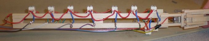
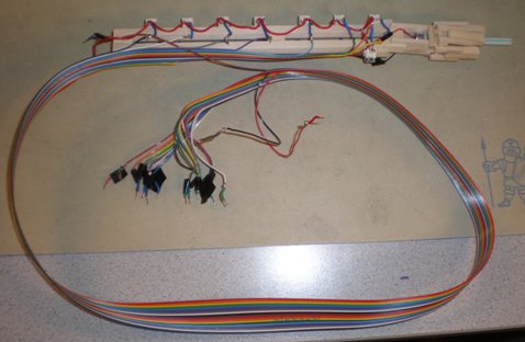
 It was very important that our controller accurately simulate a real recorder. We constructed a frame
of balsa wood with dimensions similar to a recorder. A smaller frame was attached to the front of this
structure to house the microphone and simulate the mouthpiece. This frame allowed insertion of a small straw
that could easily be replaced instead of having to clean the mouthpiece in any way.
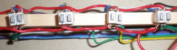
We mounted eight sets of pushbuttons on the
frame in positions they would occur on a real recorder. This means seven buttons on the top of the
frame that are divided into one group of four and one group of three, with the group
of three placed closer to the mouthpiece. The last set of pushbuttons was mounted on the bottom of the frame,
close to the mouthpiece. For each of the eight buttons on a recorder, we used a set of two pushbuttons.
This was done to be able to simulate half-covering holes, which is necessary to play certain notes on the
recorder. Running from the back of the controller is a rainbow cable with nineteen wires.
Sixteen of these go to the sixteen pushbuttons, one is used as Vcc for the pushbuttons, and two are used for
the output and ground of the microphone.
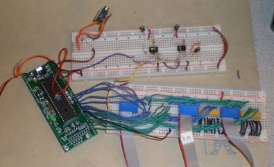
Sinces both MCUs rely on input from the controller, the output of the pushbuttons go to both the video MCU
and audio MCU. The video MCU needs the pushbuttons signals to determine the button image to display on
the screen. The audio MCU needes the pushbutton signals to determine what frequency audio signal to generate.
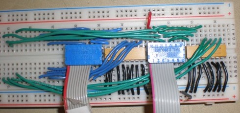
One white board is dedicated to distributing the pushbutton signals to the MCUs. The wires run from the recorder device
down to a white board, where the wires are connected to 100k pull-down resistors and distributed to the MCUs
(PORTC and PORTD on the audio MCU and PORTA and PORTC on the video MCU). The circuit schematic for the
pushbuttons can be found in the appendix here.
It was very important that our controller accurately simulate a real recorder. We constructed a frame
of balsa wood with dimensions similar to a recorder. A smaller frame was attached to the front of this
structure to house the microphone and simulate the mouthpiece. This frame allowed insertion of a small straw
that could easily be replaced instead of having to clean the mouthpiece in any way.
We mounted eight sets of pushbuttons on the
frame in positions they would occur on a real recorder. This means seven buttons on the top of the
frame that are divided into one group of four and one group of three, with the group
of three placed closer to the mouthpiece. The last set of pushbuttons was mounted on the bottom of the frame,
close to the mouthpiece. For each of the eight buttons on a recorder, we used a set of two pushbuttons.
This was done to be able to simulate half-covering holes, which is necessary to play certain notes on the
recorder. Running from the back of the controller is a rainbow cable with nineteen wires.
Sixteen of these go to the sixteen pushbuttons, one is used as Vcc for the pushbuttons, and two are used for
the output and ground of the microphone.
Sinces both MCUs rely on input from the controller, the output of the pushbuttons go to both the video MCU
and audio MCU. The video MCU needs the pushbuttons signals to determine the button image to display on
the screen. The audio MCU needes the pushbutton signals to determine what frequency audio signal to generate.
One white board is dedicated to distributing the pushbutton signals to the MCUs. The wires run from the recorder device
down to a white board, where the wires are connected to 100k pull-down resistors and distributed to the MCUs
(PORTC and PORTD on the audio MCU and PORTA and PORTC on the video MCU). The circuit schematic for the
pushbuttons can be found in the appendix here.
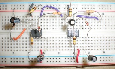 We used another white board to house an amplification circuit for the microphone.
The microphone is attached to the input of the amp circuit, and the analog to digital converter of the
audio MCU is connected to the output.
The audio amplifier circuit is neccessary because the microphone generates only very small voltage occilations
when air is blown at it. Therefore, we needed to amplify these miniscule occilations to something
on the order of a few tens of millivolts so that there is a large enough range of voltages for
the ADC to give a wide enough range of values to be useful. We designed a 2 stage audio amplifier based on
a design Prof. Land went over in lecture. We set the DC bias to Vcc/2 and use two LM358 amplifier stages, each
with a gain of about 10. The schematic of the microphone amplifier circuit can be found in the appendix here.
The output of this amplifier is sent to the ADC of the audio MCU, which used the 2.56V internal bandgap
reference voltage. We then apply a
simple algorithm (described in the software design section) in order to determine if a user is blowing
in the mic. We send a signal from the audio MCU to the video MCU that is high when the user is blowing so that the video MCU can
display visual confirmation of the note they are playing.
We used another white board to house an amplification circuit for the microphone.
The microphone is attached to the input of the amp circuit, and the analog to digital converter of the
audio MCU is connected to the output.
The audio amplifier circuit is neccessary because the microphone generates only very small voltage occilations
when air is blown at it. Therefore, we needed to amplify these miniscule occilations to something
on the order of a few tens of millivolts so that there is a large enough range of voltages for
the ADC to give a wide enough range of values to be useful. We designed a 2 stage audio amplifier based on
a design Prof. Land went over in lecture. We set the DC bias to Vcc/2 and use two LM358 amplifier stages, each
with a gain of about 10. The schematic of the microphone amplifier circuit can be found in the appendix here.
The output of this amplifier is sent to the ADC of the audio MCU, which used the 2.56V internal bandgap
reference voltage. We then apply a
simple algorithm (described in the software design section) in order to determine if a user is blowing
in the mic. We send a signal from the audio MCU to the video MCU that is high when the user is blowing so that the video MCU can
display visual confirmation of the note they are playing.
We powered the push button circuit from the video MCU and the microphone amplifier circuit from the audio MCU.
 The grounds of the two MCUs were connected together. PORTB.0 was an output from the audio MCU. B.0 was used
to indicate whether the user was blowing, and it was connected to PORTB.4 on the video MCU (B.4 was an input on
the video MCU). Additionally, SW2-SW5 were connected to B0-3 on the video MCU to control the game menu and game
reset. We also allowed the user to scroll up and down on the game menu using pushbuttons on the recorder, and
the user can blow into the mouthpiece to select an item from the menu.
We used the same simple low pass circuit from Lab 2 to convert the PWM signal to the note frequencies. We
connected PORTB.3 (output of PWM) to a low pass circuit with R=2kOhm and C=100nF.
We used the same video circuit from Lab 4, using PORTD.6 for Video and PORTD.5 for Sync, along with a 330 ohm,
1kOhm, and 75 ohm resistor. The overall schematic discussed in this section can be found in the appendix here.
The grounds of the two MCUs were connected together. PORTB.0 was an output from the audio MCU. B.0 was used
to indicate whether the user was blowing, and it was connected to PORTB.4 on the video MCU (B.4 was an input on
the video MCU). Additionally, SW2-SW5 were connected to B0-3 on the video MCU to control the game menu and game
reset. We also allowed the user to scroll up and down on the game menu using pushbuttons on the recorder, and
the user can blow into the mouthpiece to select an item from the menu.
We used the same simple low pass circuit from Lab 2 to convert the PWM signal to the note frequencies. We
connected PORTB.3 (output of PWM) to a low pass circuit with R=2kOhm and C=100nF.
We used the same video circuit from Lab 4, using PORTD.6 for Video and PORTD.5 for Sync, along with a 330 ohm,
1kOhm, and 75 ohm resistor. The overall schematic discussed in this section can be found in the appendix here.
Software Design
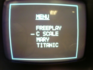 When the program starts, it enters into a menu. There are 4 options at the menu. One is "Free Play", which
allows a user to simply play notes, and view on the screen what
buttons he/she is pressing as well as what note, if any, is being played. The other options are titles
of songs for the game mode. The game involves
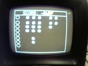
involves columns of buttons corresponding to notes scrolling right to left across the screen. On the left
side of the screen are eight open circles that display what buttons the user is currently pressing.
The user tries to play the correct note as it scrolls over the open circles. Points are awarded for correctness
and deducted for errors. This game closely resembles Guitar Hero. This similarity was originally unintended,
but when we discussed ideas of how to show the user what to play, we decided that this would truly be the
best way to do it. But with our game, since our controller accurately simulates a real recorder,
playing the game is a learing experience as well.
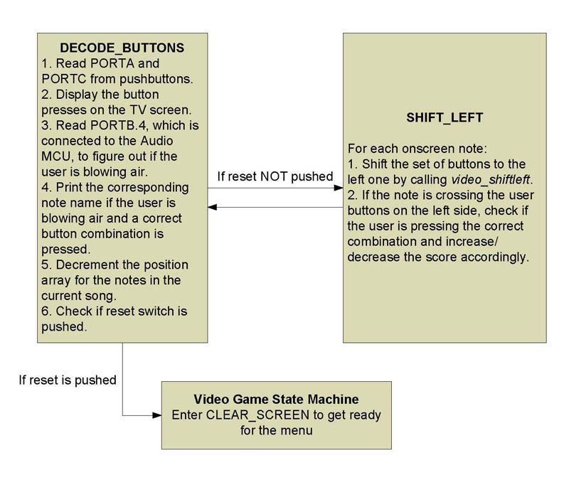
The diagram here is a state machine for the game menus.
When the program starts, it enters into a menu. There are 4 options at the menu. One is "Free Play", which
allows a user to simply play notes, and view on the screen what
buttons he/she is pressing as well as what note, if any, is being played. The other options are titles
of songs for the game mode. The game involves
involves columns of buttons corresponding to notes scrolling right to left across the screen. On the left
side of the screen are eight open circles that display what buttons the user is currently pressing.
The user tries to play the correct note as it scrolls over the open circles. Points are awarded for correctness
and deducted for errors. This game closely resembles Guitar Hero. This similarity was originally unintended,
but when we discussed ideas of how to show the user what to play, we decided that this would truly be the
best way to do it. But with our game, since our controller accurately simulates a real recorder,
playing the game is a learing experience as well.
The diagram here is a state machine for the game menus.
 The video MCU uses code based heavily on that developed by Prof. Land for Lab 4. An array
is used to store in memory values of the pixels to be displayed on the television. We often needed to change
a large number of pixels in the video memory at once, but there is a limit to the number of changes that
can be made to video memory in each frame without causing video artifacts.
To successfully output video, we utilized buffers in order to
update as much of the screen as we possibly could in each frame. To further
minimize the number of pixels that need to be updated, we wrote functions that can shift the image
representing a button left by 1 pixel with a minimum number of pixel updates. The diagram here
is a state machine for the video buffers we used.
The video MCU uses code based heavily on that developed by Prof. Land for Lab 4. An array
is used to store in memory values of the pixels to be displayed on the television. We often needed to change
a large number of pixels in the video memory at once, but there is a limit to the number of changes that
can be made to video memory in each frame without causing video artifacts.
To successfully output video, we utilized buffers in order to
update as much of the screen as we possibly could in each frame. To further
minimize the number of pixels that need to be updated, we wrote functions that can shift the image
representing a button left by 1 pixel with a minimum number of pixel updates. The diagram here
is a state machine for the video buffers we used.
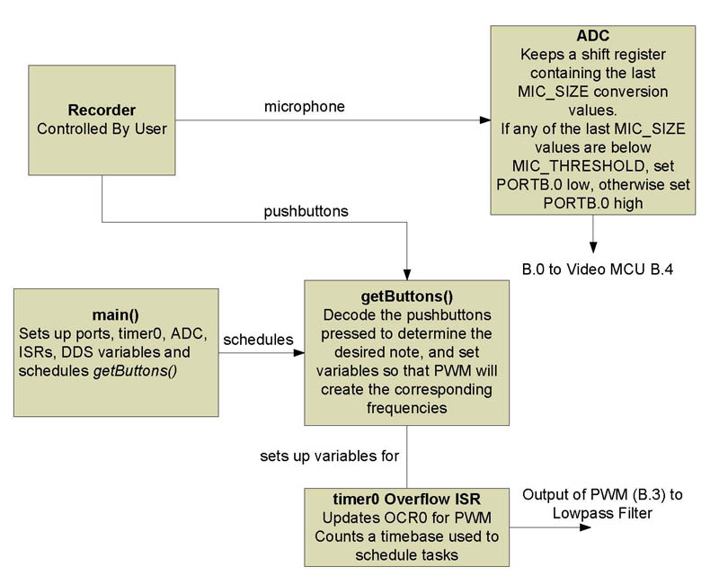
The MCU dedicated to producing audio uses Direct Digital Synthesis (DDS). We use the MCUs pulse width modulation (PWM) capability to generate pulses, which are then passed through a simple first order low-pass filter to produce a signal at a desired frequency. The frequecy depends on the width of the pulses. The audio MCU gets inputs from the pushbuttons and compares the buttons being pressed against a set of hardcoded values representing buttons that correspond to actual recorder notes. We got these button combinations from the table here. We chose the C tuning because it gave us a good range of frequencies for playing most songs. We used fixed point multiplies to fade in and fade out the audio signal to get a clean transistion with no pop. The ADC of the audio MCU takes as an input the result of the amplified microphone. When the user is blowing and holding a correct combination of buttons, the corresponding note is output. If the user blows but is not playing a real note, a 'bad' note is generated.
When a user blows into the microphone, the amplitude of the signal at the output of the audio amplifier increases. Since we biased the audio amp to Vcc/2, or 2.5V, when the user is not blowing, the input to the ADC will stay right around 2.5V. When the user blows, the signal will oscillate between around 2.3 and 2.7V. We used the ADC converter of the audio MCU with the 2.56V bandgap voltage reference. This gives an ADC value of 255 for voltages greater than 2.56V, and 0 for 0V. In our program, we keep the last several values (MIC_SIZE) of the conversion. If any of these values is below a certain threshold (MIC_THRESHOLD), the ADC has recently seen a lower input voltage, so we can assume the user has been blowing into the microphone.
The diagram to the here shows the structure of the code for the audio MCU.
Design Results
We were able to prevent any hesitation or flickering on the screen by using buffers to split up the updating of the video, and by using a dedicated audio MCU to generate sound. Our use of fixed point arithmetic and enveloping the audio signals also minimized the amount of popping and distortion heard while playing notes on the recorder. To generate the correct notes, we rounded the incrementer used to the nearest integer. We meausred the synthesized frequencies and found they were very close to the actual desired frequencies.
To enforce saftey in our design, we made sure that no large voltages or currents ever occured. Also, all open electrical connections are wrapped in electrical tape to further prevent the chance of shock. However, if we were to market our idea, several stricter saftey precautions would need to be met. For example, our current device leaves much of its electrical components exposed. We did this primarily so that if something came loose we could easily fix it. A more finished device would need to be housed in a more sturdy container. Our device was a closed system, and did not use RF transmission so it did not interfere with other peoples projects.
We are very pleased with the usability of our project. The recorder is fairly straightforward to use, and provides a close approximation to what playing a recorder is like. Also, our game is designed to provide the user with a learning experience that does not leave him/her frustrated. Repeatedly playing the songs definately gets a user accustomed to playing the recorder. Also, by displaying the note being played alongside the buttons pushed, a user can learn what notes they are playing, and possibly reproduce them in the future.
Testing Back to top
Hardware Testing
As we built components for the hardware portion of our project, our general testing strategy was to first
isolate a circuit and test it by itself, and then integrate it with the rest of the system and test the entire system.
Generally, we tested parts of the project where we expected potential problems. Other issues we dealt with as they came
up. This section contains is a summary of some of our own tests as well as problems we encountered and how we dealt with them.
Early on, we realized that we would need wires with a length of a few feet to connect the recorder controller to the rest of the circuitry in order to provide enough range of motion for a comfortable user experience. We were worried that a closely bunched group of wires over a 3-4 foot distance may distort signals sent over them. We were not sure the effect this would have, so we improvised a simple test by connecting four of our push buttons to four LEDs on the MCU through four foot long wires. We also used a potentiometer to measure the voltage from the switchs to ground. We found that the LEDs lit up as expected, and the potentiometer showed no significant degradation of Vcc along the length of wire. We were also worried that the very small signal output by the microphone would get overcome with noise before it travelled the three feet to our amplification circuit. Early in the project, we tested the microphone circuitry with very long wires, and found that long wires would not be a problem for out microphone circuitry either.
Because the pushbuttons from the recorder lead to ports on both the audio and visual MCUs, the MCUs were linked to each other though this connection. We were worried that this could cause errors when reading inputs due to differences in Vcc. After discussion with the TAs, we decided to link both MCUs to a common ground. This measure ensures that logic high values and logic low values will be interpreted the same way by both MCUs.
One problem we encountered early on was a degrading of Vcc when several pushbuttons were simultaneously pressed. We noticed this error when the MCU began incorrectly detecting that someone was blowing into the mic while many buttons were pressed at once. Measuring the voltages of the mic amplification circuits, we soon realized that the DC bias for the op amps, which was supposed to be 2.5 volts, was sightly lower that it should have been. Tracing the problem back, we saw that the Vcc being fed into the amplification circuit was below 5 volts. To solve this, we changed the values of the pull down resistors we were using for the buttons from 10 kOhm to 100 kOhm, in order to reduce the amount of current drawn when the buttons were pressed.
Software Testing
 Most of the software testing we did involved tweaking different variables in our video and audio code in order to
get a desired effect. Our variables were mostly found empirically by just playing the game. We would try one set of
variables, view the results, and then tweak them to try to improve the experience. The video and audio optimizations we made are
described in detail in the Software Design section.
Most of the software testing we did involved tweaking different variables in our video and audio code in order to
get a desired effect. Our variables were mostly found empirically by just playing the game. We would try one set of
variables, view the results, and then tweak them to try to improve the experience. The video and audio optimizations we made are
described in detail in the Software Design section.
Our original audio code did not contain any measures to prevent popping from the speakers when a note started or stopped playing. We first implemented shifts to fade in and fade out the signal. This worked better than using no envelope at, but we could still here some popping (specifically, 8 quick, quite pops for each of the bit shifts). We dediced to switch to using a fixed point multiply to be able to multiply by a constant other than just 2 (the only value possible using shifts). We empirically determined the multipliers to use to get quick fade in and fade out of the output signal without popping.
In the video code, we encountered an issue with storing the notes for all of our songs. We intially just used an array, but as we added songs this array got so large that it generated a warning that the hardware data stack size was 'dangerously low'. We first attempted to remedy this by storing the data in eeprom. However, retrieving the data from eeprom appeared to be too slow (it caused artifacts to appear on the television). We then decided to store the array in flash. After making this change, the visual artifacts stopped appearing and we did not encounter any hardware memory warnings.
Conclusions Back to top
Accomplishments
Our final project resulted in a system that provides an interactive environment for learning to play the recorder. We think are main accomplishments are:
- An electronic recorder that uses pushbuttons and a microphone to accurately simulate playing a recorder.
- A smooth sounding audio component with minimum distortion that plays back notes corresponding to what buttons a user pushes on the recorder.
- A video system that allows a user to see what buttons they are pushing along with what note is being played.
- A game teaches users songs by having them play notes as they scroll across the screen.
Expectations
The final design we implemented met just about all of our goals. We managed to make a device that accurately simulated playing the recorder, as well as create a user interface and game to coincide with our device that provided a way for a user to learn how to play the recoder. We did not, however, have time to implement some of our more complicated ideas, such as making our recorder wireless or implementing a way to store what a user plays into memory for future playback.
Future Development
Given the time, there are several items we would have liked to add to our project. One is the ability to display held notes on the screen. Currently, only short notes can be displayed, and any song that requires a note to be held will not be accurately represented scorewise.
Another function we wanted to add was the ability to record songs the user plays, allowing users to create their own recordings and incorporate them into the game. One problem that hindered us from doing this was that we could only display a certain number of notes on the screen at once, so if a user tried to make a song with too many notes too close together, problems would occur when trying to scroll the notes across the screen. Also, as stated above, if a user tried to record a held note, this would not be accurately stored. We would also need an efficient way to store user-created songs in memory.
We also wanted to incorporate a way that would make it easier to add songs to those stored on the MCU, possibly involving MIDI files (the Guitar Hero series uses MIDI files to represent songs). Our current method of representing songs is very simple and primitive, making it hard to add new songs. We store the songs in an array in flash memory with a format that stores the current notes along with the distance in pixels to the next note. To add a song, we must approximate the time between notes by directly setting the number of pixels between them, and test to see if playing the song sounds right. Creating an easier way of doing this would definately be beneficial.
Currently, we simply produce the tones corresponding to the exact frequencies of a note being played. This is a very close approximation to an actual recorder, as a recorder produces very few harmonics other than the base frequency. However, tweaking our audio code to sound more like a recorder could enhance the user experience.
Making the device wireless to get rid of the wires connecting our recorder to its base station is another step we would have liked to make given time. This could have given the user a greater range of motion while playing, as well as provided a more accurate simulation of playing the recorder.
Standards, Intellectual Property, and Legal Considerations
Our project did not have applicable standards we needed to conform to. We also do not have legal considerations that relate to our project.
Of great help to us was the video, pulse width modulation, and fixed point arithmetic code developed by Professor Land. These pieces of code provided the building blocks or our project and allowed us to implement all of the parts of our design. We also used an ASCII character bitmap created by David Perez de la Cruz and Ed Lau for their ECE 476 final project a few years ago (found here). Besides for this code, we did not use any other code written by other people.
Ethical Considerations
We closely followed the IEEE Code of Ethics throughout the design of our project. We made no desicions that would in any way danger the public or environmental safety. We did not have any conflicts of interest throughout our project, except possibly when competing for lab space. When lab space was limitted, we did whatever the TA or Prof. Land told us to do. All claims made in this lab report are true to our best knowledge. We always made sure that any hardware we used were not already part of someone elses project. We never took parts if it was possibly someone else was using them. Whenever somebody had questions or critism for our project, we respectfully listened and did our best to respond intelligently and appropriately. If their idea was good, and helped us with our own work, we accepted and used it, giving them proper credit. All code or circuitry used in our project that has been designed by someone else has that person properly credited in this lab writeup. If we saw that somebody was making a mistake, we were quick to politely correct them while the mistake was still easy to fix. If a fellow student had a question that we could answer, or was looking for a tool or part that we had access to, we were quick to let them know that we could help. By ensuring that we took into account all of the above, we maintained the code of ethics laid down by the IEEE.
Appendix Back to top
Code
Schematics
Pushbutton Circuit Schematic
Microphone Amplifier Schematic
Top-Level Schematic
Code Block Diagrams
Video Game State Machine

Video Buffer State Machine
Audio Program State Machine
Cost Breakdown
| Part Name | Part No. | Quantity | Price Per Part | Total |
|---|---|---|---|---|
| STK500 | - | 1 | $15.00 | $15.00 |
| White Board | - | 2 | $6.00 | $12.00 |
| Mega32 | - | 1 | $8.00 | $8.00 |
| Pushbutton | digikey P13588S-ND | 16 | $0.37600 | $6.02 |
| Custom PC Board | - | 1 | $5.00 | $5.00 |
| B/W TV | - | 1 | $5.00 | $5.00 |
| Power Supply | - | 1 | $5.00 | $5.00 |
| 2 Pin Connector | - | 4 | $1.00 | $4.00 |
| Wood | - | - | - | $2.00 |
| 9V Battery | - | 1 | $2.00 | $2.00 |
| Microphone | allelectronics CAT# MIKE-74 | 1 | $1.00 | $1.00 |
| Straws | - | Many | Sampled From Mattin's | $0 |
| Op Amp | LM358 | 2 | Lab | $0 |
| Capacitors, Resistors | - | Many | Lab | $0 |
| Total Cost | - | - | - | $65.02 |
Task Breakdown
| Colin | Joseph |
|---|---|
| Built Recorder Structure | Built Recorder Structure |
| Website Content | Website Content |
| Game Code | Game Code |
| Built prototype board | Implemented DDS and video optimizations |
| All Soldering | Drew Schematics |
| Designed Webpage | Programmed songs |
| Frequency Testing | Game menu design |
| Debugged microphone amplifier | Designed microphone amplifier |