Karan Khanna
(kk364)
Amit Penmetcha
(ap328)
Introduction
For our project, we designed a glove that can be used to control the Cornell
University robotic Snake arm– thereby enabling a surgeon to remotely operate
the snakearm as a colonoscope in conjunction with a vision guide system (aka TV
goggles). The glove allows for movement of the arm's segments as a whole and
individually.
More about the SnakeArm
A snake arm
emulates the movement of a snake, with one point of attachment where the arm is
anchored. It has multiple degrees of freedom, high flexibility, and thin
diameter.
The current
generation snakearm has been designed to be used in surgical applications –
particularly colonoscopy. The need for a friendly control method emerged
earlier in the course of our team efforts. The motion sensing glove is designed
to meet this need by controlling the servo motors on the snakearm indirectly
through the PC based on its movement.
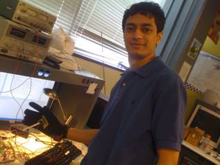
The glove is composed of three types of sensors – flex sensors, a two
axis accelerometer and several hall effect sensors. The flex sensors are used
to select modes of operation, the accelometer is used to generally move the
snakearm while the hall effect sensors are designed to enable precise control
of the head
The vision
guide system is the part that makes this project more appealing to surgeons.
There is a camera mounted on the head of the snakearm itself and the camera is
connected to TV goggles. So, the surgeon is able to control the snakearm with
the glove while using the vision guide system to see inside the colon of the
person being operation on. This is very much like playing a video game and this
glove based system has been designed to enable remote colonoscopy surgeries.
For more information
on the current snake arm capability, please see this youtube video.
http://www.youtube.com/watch?v=_ByB35gTuuI
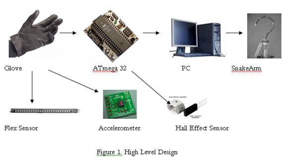
II. High Level Design
Our idea came from our
involvement with the snake arm team and the wish to control it in a more
logical fashion. Having it mimic the movement of a person's arm would allow
them to have a more complete and powerful control over the arm allowing them to
move it exactly as they please. The snake arm team is currently developing the
snake arm for a surgical application, thus, accurate control is very important.
The project consists of the Mega32 serving as an interface between the hardware
and the snake arm interface. Using an accelerometer we determined the user's
hand motion on the x and y plane, which controlled the base of the snake arm.
The tilt determined the arm's movement vertically, while the pitch/roll
determined the movement of the arm horizontally. The flex sensors were used to
activate and deactivate the hall effect sensors, which were used to control the
head of the snake arm. The flex sensors and accelerometers went into the ADC of
the Mega32, while the hall effect sensors go into PORTB. The inputs from the
hardware components are calibrated and reformatted into two bytes that are sent
across the serial port to a java interface that manipulates the snake arm.
One
of the questions we asked ourselves earlier in the project was whether we
should use send the data from the glove through the ATmega32 to the PC (hence
snakearm GUI) or connect our ATmega32 directly to the snakearm servo motors and
send out PWM signals to move them. However, keeping in mind that the snakearm
is quite complex – just four segments of it amount to 12 motors and each motor
has to moved in a perfect puppetering action with regard to the other motors to
move a segment in a simple direction. Since a control system was already
implemented for the snakearm in Java, it made no sense not use it and try to
reinvent the wheel.
III. Program/Hardware Design
Hardware Details
The hardware we used consisted of the STK500 programming board, Mega32
microcontroller, a two axis accelerometer (Freescale MMA6261Q 1.5g accelerometer),
5 flexsensors (FLX01), and 8 Allegro 1101 Hall Effect Sensors. We also used a
Freescale 9V battery to 3V converter, which served as the supply voltage to the
accelerometer. The accelerometer's x and y axis outputs tied into Pin A.0 and
A.1. The flex sensors and hall effect sensors were both inputted into
LM258/LM358 opamps and used a non-inverted style setup to amplify their voltage
The hall effect sensors outputted digital signals that were amplified to 3.6 V,
which is logic high. The sensors detect fluctuations in magnetic fields, so
when a magnet is held next to one, the sensor goes low. The flex sensors also
went into opamps to get a gain into a range of .5 - 2 volts, based on how much
the sensor was bent. The greater the degree of bending the lower the output
voltage. The output voltage is determined based on the equation Vin * R1 / (R1
+ R2), where R1 is the other input resistor to the non-inverting terminal.
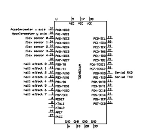
Figure 2: ATMega32 Connections
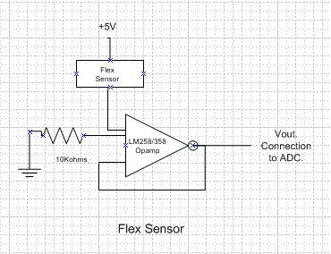
Figure 3: Flex Sensor circuit diagram

Figure 4: Accelerometer Circuit Diagram
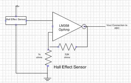
Figure 5: Hall Effect Sensor Circuit
Diagram
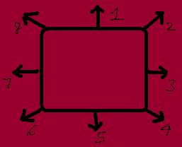
Figure 6: Hall effect sensor direction
diagram
with respect to sensor number
Hall Effect Sensors
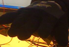
Glove with
fingers stretched out:
Glove
in a fist form: Accelerometer
Accelerometer
on and hall effect sensors off
off and hall effect sensors on
Program Details
We had one task that handled all of the inputs to the ADC and activity of the
hall effect sensors. We first read the x-axis on the accelerometer from the ADC
and then the y-axis(on the second iteration of the task) by incrementing the
ADMUX variable. In the case that this was the first reading, these inputs were
used to calibrate the readings from then on. We then got readings on the flex
sensors in one iteration, by using a for loop that constantly incremented the
ADMUX and polled the next port. We compared the reading on the flex sensor to a
reference value. If it was less than that we determined that the flex sensor
was being bent significantly. We used an array to store the pattern of flex
sensors that were being flexed.
To actually get readings from the ADC, we used an ADC interrupt that gave us
the latest conversion whenever it was ready. We used a sleep command when
making the ADC read the next port, so that we could give it enough time to make
the conversion to an accurate value. We noticed early on that we were getting
random values from the ADC and after consulting the websites for previous mouse
type projects we found that the sleep command could be used to help give the
ADC ample time to make the conversion.
The id of the hall effect sensor that was activated was only transmitted when all of the flex
sensors were being bent. Another interrupt was used to determine which of the
flex sensors were being activated.
Sending the data across the serial port was done in three bytes. The first byte
was merely a buffer byte, so that the Java interface could determine the order
in which the bytes were being sent. The second byte consisted of the flex
sensor array and whether or not the hall effect sensors had be activated. The
third byte consisted of the reading from the accelerometer or the identity of
the hall effect sensor that was being used. The upper nibble of the byte stored
a 3 bit value that ranged from 0 to 4, which determined how quickly the user
wanted to turn on the x-axis. The msb bit was used to determine direction. The
lower nibble contained identical information on the y-axis. The byte would
contain the ID of the hall effect sensor that was activated if they were being
used. Our java interface opened a line of communication with the
microcontroller and polled the serial port for data. We used queues to handle
the quick stream of data and extracted the necessary data from them, before
sending them to the snake arm interface. The snake arm is controlled by a
program that communicates to the servo motors via the ATiny26. The program gets
feedback from the ATiny26, so we obtained the current position of the snake arm
and updated to where we would like it to move based on our readings from the
accelerometer and hall effect sensors. This last part of interfacing was done
with the assistance of one of the CS members of the snake arm team. The code
for the microcontroller and serial interface with microcontroller is provided.
However the snake arm interface could not be provided and is not really
necessary for the user to see anyway.
1st byte - 1100000000 (buffer)
2nd byte - 2 bits - not used, 5 bits (Flex sensor array) 1 bit (Hall Effect or
Accelerometer)
3rd byte - 4 bits x axis acceleration 4 bits y axis acceleration or 8 bit id of
hall effect activated
These three
bytes are sent through the UART (serial) interface to the computer where a Java
program picks them up (GloveCommunicator.java) and interprets the data. A
program runs as a new thread so that it takes up less CPU power while polling
the COM port as necessary. Next, this data from this program (sensor positions)
are extracted by the CU SnakeArm GUI which runs them through its programmed
control system and moves the servo motors controlling the snakearm accordingly.
Looking back at
the program implementation sector of our project, the serial communication and
interfacing with the snakearm GUI and control system proved to be quite tricky.
There were numerous errors that we encountered from bad values, inconsistent
formats, etc. Moreover, integration this into an existing yet functioning
platform proved to be demanding.
IV. Results of the Design
We adhered to the standard
format of communication over the serial port. We used a baud rate of 9600 bps,
sent 8 data bit packets, had 1 stop bit, and no flow control or parity bits.
Although we were receiving at this rate on the computer end, we only handled
data every half a second, dropping all other packets. The reason for this was to
avoid overdriving the servo motor. The response went down as a result, but is
still acceptable. This was needed for the safety of the snake arm. We also
enforced safety in the glove by keeping the flex sensors within one of the
layers of the glove and keeping the accelerometer on small breadboard on top of
the glove to give it a proper shielding from any static that could form on the
glove. Our project does not interfere with any other devices in any way.
Overall, the snakearm does respond to our glove and the sensor readings on the
GUI correspond properly to our sensors. However, the movement is not very
smooth. This is a restriction from the existing control system which we did not
create or modify in this project.
Our results
mostly met our expectations. We were able to communicate the hardware and our
software talks to the snake arm extremely effectively. Synching up our project
with the snake arm interface is almost flawless, and we have maintained an
efficient scheme for running a constant poll on the serial port that does not
slow the CPU. We had to force a delay between the users control movements and
the snake arm's response. We purposely drop many of the users commands, so that
the snake arm is not overloaded with movement requests, which results in a
substantial delay. Considering the snake arm is small and can break easily,
this was a necessary flaw we had to keep in the project. The movement of the
snake arm matches the general movements of the glove, but the overall snake arm's
control algorithm has yet to be perfected. As a result, the snake arm is able
to move in the general direction that the user picks, based on both the
accelerometer and the hall effect sensors, but the snake arm starts to bend in
the direction it is moving, causing it to form awkward positions that are not
consistent with the user's commands. The glove serves as a suitable replacement
for the current form of control, thus, we accomplished our primary goal of
having a solid control scheme for the snake arm. In the future we would like to
use a 3 axis accelerometer and or a different scheme that allows the user to
move his/her entire arm in which the snake arm will follow. However this relies
on our fine tuning the current control algorithm for the snake arm. Also the
hall effect sensors were quite difficult to use, as we had to have the magnet
at an exact orientation to activate them. In the future we will try using some
other mechanism to give us an additional level of control over the snake arm.
The other good part about our design is that it is very modular. Reassigning
the function of a particular sensor is easy since all the sensor readings are
sent to the Java program.
Intellectual Property and Ethical Standards
Our project fully complies with the IEEE Code of Ethics. Our glove controller
was designed with safety in mind and is environmentally friendly and safe. The
snake arm is meant to be used for beneficial purposes. We generated all of our
code on our own, but when troubleshooting, we used the sleep command mentioned
by a previous year's project. As mentioned previously, we used the snake arm's
current interface and control algorithm and received help from a member of the
CS team to help us communicate with the snake arm, due to our lack of knowledge
of how the interface worked. We did research on how to communicate across the
serial port using Java, and wrote our program based on the tutorials available
and the style that the snake arm team wished us to follow. This idea is not
completely new, however we have made a device for a fairly unique purpose. We
did not accept any forms of bribery nor did we offer any bribes. We welcomed
any help from
Legal
Considerations
We did not use
RF transmitters or any other components that can cause interference with other
devices, thus there were no legal issues that we had to consider.
Appendix:
Cost:
|
Part |
Cost |
Part Number |
|
Stk500 + Mega32 |
Free (SnakeArm team provided) |
Not needed |
|
Flex Sensor (5) |
$12.95 * 5 = $64.75 |
Imagesco: FLX-01 |
|
Accelerometer |
Free (Sampled from FreeScale) |
FreeScale: MMA7260QT |
|
OpAmps |
11*$1.00 (Lab Fee) = $11.00 |
LM358 |
|
Glove |
$1.00 |
Not Needed |
|
Hall Effect Sensors (8) |
Free (sampled from Allegro) |
Allegro A1101EUA-T |
|
Jumper Cables |
2*$1.00 = 2.00 |
Not Needed |
|
Several Breadboards |
Free (SnakeArm provided) |
Not Needed |
|
Freescale 9V to 3V battery converter |
Free(sampled from freescale) |
Not Needed |
|
Total |
$78.75 |
|
Note: since this is a project team
related project, our budget was waived.
Breakup of Work
Testing and designing
hardware
(Flexsensors,
Accelerometer, Hall Effect Sensors): Karan & Amit
Microcontroller
software in C: Karan & Amit
Java Serial
Interface: Karan & Amit
Integration
with SnakeArm: Karan & Amit with help from Bryant Williams
Webpage: Karan
& Amit
Code
Data Sheets
Links
Cornell University Snake Arm
Project team