Matthew Pokrzywa (mjp63)
James Du (jsd46)
Wednesday Lab 1:25-4:25
|
Our project is a two player tilt controlled video game based on the classic Light Cycle arcade game. The purpose of the game is to guide your player through the arena avoiding the boundaries and trails created by you and your opponent. Whichever player causes his or her opponent to crash is victorious.
Our project was divided into three portions: the actual game software, the tilt controllers, and the video generation. The control scheme used accelerometer based controllers to allow the user to turn, speed up, and slow down by tilting the controller. To achieve high resolution color video with a good frame rate, external hardware was used to generate the synchronization timing and RGB TV signal. The backend software components for the controllers and video generation was broken down into modular componenets. The game software was written specifically to interface with these controller and video generation libraries. |
|
The goal of our project was to make a game for the color TV that would use novel controllers. The source of the idea for our game is Light Cycle from the movie Tron, and we decided on using accelerometers in our controllers to make it novel. We chose Light Cycle because it is a game that color greatly improves both visually and in gameplay (because it helps differentiate between the two players), and accelerometers are good controllers for it in that they help mimic a pilot’s controls and a two dimensional accelerometer has all the different inputs that we need to control one player. Our game is based on the arcade game but has two human players, and the Light Cycles are controlled by accelerometers.
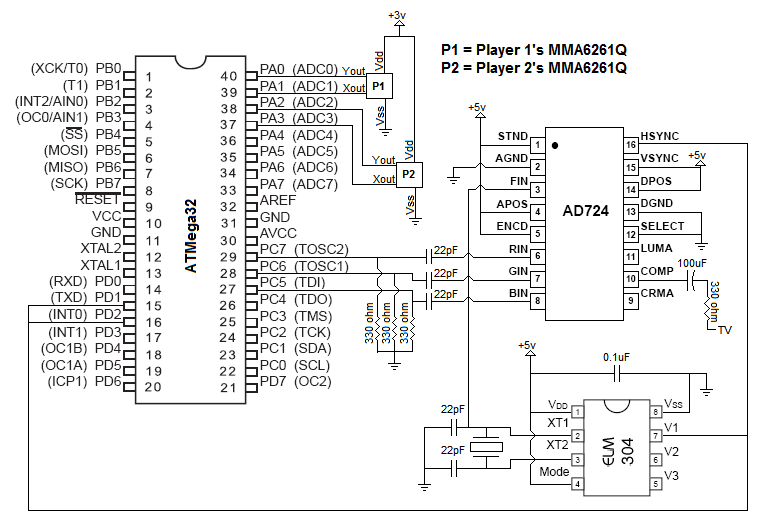
This diagram illustrates our high level design: 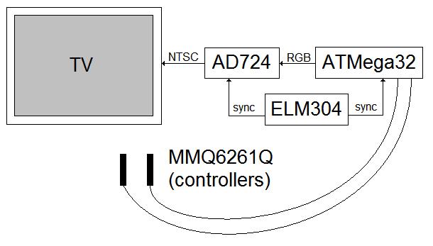
The ATMega32 microcontroller runs the game and creates an RGB signal for the AD724. The ELM304 sends a composite sync signal to the AD724 and microcontroller. This syncs the AD724 and microcontroller, and makes it possible for the microcontroller time the RGB signal. The AD724 encodes the RGB signal into a composite video output to send to the color TV. Design Tradeoffs Our design involved many software/hardware complexity tradeoffs. These tradeoffs mainly involved the controller design and color TV generation portions of our project. In the controller portion, we needed to decide where to place to ADC input multiplexing mechanism, and in video generation portion, we had to decide where to place the synchronization mechanisms. Standards, Copyrights, and Legal Considerations This project exports a signal to a color standard television and it must conform to the NTSC television standard. We needed to include a 3.58 MHz sideband for the color TV signal, and also provide the red, green, and blue (RGB) values for this sideband. Our adherence to this standard is discussed in more detail below. We awknowledge that the rights to Tron are owned by Disney Corporation. Our Light Cycle game is inspired by the Light Cycles subgame of the 1982 arcade video game based on the movie. We are not in violation of any copyrights as our game is only very loosely based on the original arcade classic and is not distributed for profit. |
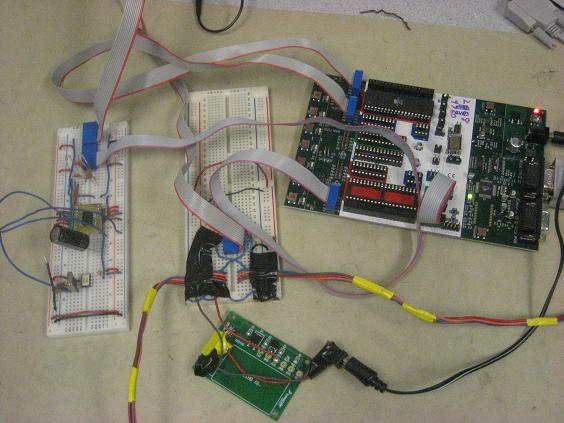
The circuit we built for this project is comprised of the ATMega32 microcontroller, ELM304, AD724, and wires leading to the two MMA6261Q accelerometers (partially wrapped in yellow electrical tape). The schematic is in the appendix.
The color TV signal generation part of the circuit is a modified version of the circuits we studied from previous years' Color TV projects. Initially, we had three DAC’s for our RGB inputs to the AD724. There were three bits for red, three bits for green, and two for blue. Later we realized we only need three distinct colors for our game, so one bit for each color is more than enough. We also increased capacitances for the AC-Coupled RGB inputs to get a sharper image on the TV. The crystal oscillator setup for the AD724 gave us poor video quality, so we tried hooking it up to the same crystal we used for the ELM304. This greatly improved our results.
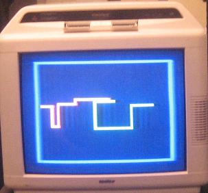
The ELM304 is originally intended to be used to generate a solid white raster or a four-level grey scale pattern to provide a stable video input signal for use while recording audio in video cassette recorders, but we use it to generate a composite sync input to the AD724 and let us know which phase of video generation our ATMega32 should be outputting. The outputs from the ELM304 (V1, V2, and V3) change during each signal phase according to the following chart taken from the ELM304 datasheet: 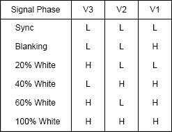 White raster mode is used in our project, so only sync, blanking, and 100% white apply. We hooked the output from V1 to two of our port pins for two interrupts. The video signal we are generating should look like the following: 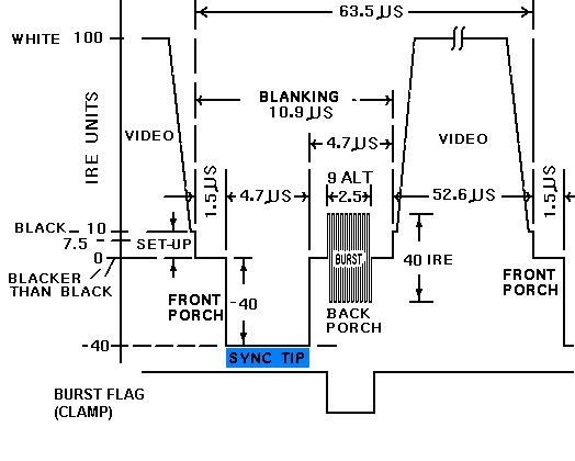 V1 lets us know when the video signal enters and leaves the sync phase (highlighted in blue above). Which kind of pulse the AD724 is outputting, which line to display, and when a new frame should start is kept track of in the interrupt code.
The AD724 encodes red, green, and blue color component signals into their corresponding luminance, chrominance, and composite video output signals in accordance with NTSC or PAL standards. We use NTSC since that’s the North American TV standard. The microcontroller generates the correct RGB signal and the ELM304 generates the composite sync signal. Controllers MMA6261Q These diagrams from the MMA6261Q datasheet helps illustrate how this accelerometer works: 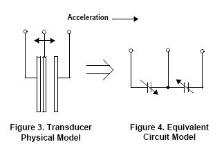 In the physical model, when a force is applied to the structure, the center beam moves closer to one of the fixed beams and farther from the other. The change in distance can be used to measure acceleration. The same principle is applied to the equivalent circuit model. When a force is applied, the center plate moves, and each capacitor’s value will change following the equation C = AT/D (A = area of plate, T = dielectric constant, D = distance between plates). We used these accelerometers as controllers for our game. They are both hooked up to port A of the microcontroller, and the ADC rotates through polling all of them (it checks player 1’s X acceleration, then player 1’s Y acceleration, then player2’s X acceleration, then player2’s Y acceleration). Tilting the accelerometer forwards accelerates, backwards decelerates, left turns left, and right turns right. The accelerometers we used were already soldered onto boards for us, so we just had to wire them to our ports. The boards are covered in insulating foam and encapsulated in cardboard boxes which are wrapped in electrical tape to ensure the player’s safety. A hollowed out pen is tape just below the cardboard box to make the controller easier for the player to hold.
The MMA6261Q’s needs a 3 volt supply at Vss. Initially, we tried to build a voltage divider using one of the microcontroller’s Vss port pins. This failed and made us think we had burned out the accelerometers because we were getting bad voltage readings. The regulator board fixed our problem. |
The software portion of this system was broken down into three modular components: the controller software, the video generation software, and the game software. The controller and video generation software components were designed indepedently and with the goal of elegantly interfacing with the game software.
As such, the Light Cycle game software was implemented without breaking this abstraction. It interacted with aforementioned components only when necessary, and only through cleanly defined interfaces.
The controller software interface was responsible for converting the analog voltage signals from the accelerometers into digital information specifying a player's action. As mentioned above, a player can tilt the controller left or right to turn accordingly, or tilt the controller forward or backward to change speed. A interesting challenge we needed to overcome was the fact that the Mega32 MCU can only do a single A/D conversion at a time, but we had 4 inputs in need of conversion (X and Y for each controller). We decided that the simplest way to solve this was to multiplex the conversion in software. Every time the game state is updated in the software, the ADC is polled. Since the game is updated at a rate way faster than what a human can resolve, we decide to have the ADC cycle which accelerometer reading it converts. Using a simple modulo 4 counter, we cycle between ADC inputs and so acquire a new reading for a specific controller axis every four game updates. Another interesting controller problem that needed to be overcome in the software was the fact that the accelerometer readings were inherently unstable. This coupled with the fact that an average human hand will jitter the controller as it is being used resulted in unstable and unreliable readings. Controller tilts were registering as the same action multiple times when not intended, and tilting the controllers back to neutral often resulted in a registering of a move in the opposite direction. To overcome this problem we decided that our tilt controllers must be debounced in the fashion very similar to the one used for various sorts of keypads and pushbuttons in previous labs. Here is a diagram of our state machine for each controller: 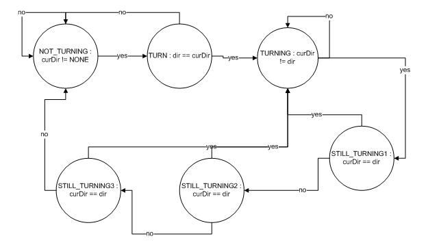 The three addition states for verification that a different move is performed were necessary in order to prevent the controller and ADC from registering an opposite move after the player returns to the neutral position. Here is a listing of the controller functions we wrote and a description of what they do:
The color video generation portion of the project software was the most taxing and time consuming. We borrowed much of the video generation code from previous semester projects, but we had to modify it extensively to fix bugs and make it fit our application. Low Level Video Generation The video generation code is made up of the sync interrupt and the display interrupt. The sync interrupt syncs the microcontroller with the sync generator (ELM304) and the AD724, and turns on the display interrupt at appropriate times. The display interrupt figures out which frame it’s on, and then takes bytes from the screen array and pushes them to Port C. There are 63.5 microseconds allotted for game code to run during the non-display lines. This should be 1,016 clock cycles. Here is a listing of the interrupts and functions we wrote and a description of what they do:
On top of the implementation of the low-level video generation framework we built a higher level video library that abstracts away the low level hardware and assembly manipulation. This layer simply accesses the screen array and modifies its contents accordingly. We implemented this layer with the Light Cycle game in mind, but we made the library general enough to be used to create any sort of simple color television application. Here is a listing of the video library interface functions we implemented and a description of what they do:
The code implementing the Light Cycle game itself was conceptually simple once the controller and video generation framework was in place. Most challenges in this part of the software related to game playability, and were not very technical in nature. Technical issues regarding the game software involved solving ODEs for position and velocity and doing collision detection.
Differential equations for the position and velocity of the Light Cycles needed to be solved at every game state update. Solving differential equations is another computationally intensive operation, so to conserve cycles we used a simple explicit numerical integration scheme. Euler’s method was chosen because of its computational simplicity. A step of Euler’s method takes one addition and one multiply. We solved the following equations using Euler’s method: vx(t+dt)=vx(t)+acc*dt and vy(t+dt)=vy(t)+acc*dt x(t+dt)=x(t)+vx*dt and v(t+dt)=y(t)+vy*dt We were able to further optimize this computation by setting the dt time step to 1, and therefore eliminating the multiplication step of Euler’s method and reducing the integration algorithm to nothing more than a single addition. Collision Detection This notoriously difficult aspect of game design had a very elegant solution in our Light Cycle game software. By the rules of the game, the first player that collides with anything (either player's light trail or the arena boundary) loses, so collision detection simply reduced to checking if the pixel the player is about to move onto is turned on. Playability Considerations Nontechnical playability aspects of the game ended up being the most amount of work in the game software phase of our project. These concerns included initial player positions, velocity and acceleration ranges, and controller sensitivity. Tweaking these parameters to make the game as playable as possible involved trial and error modifications until we felt the game was as playable as possible. Here is a listing of the controller functions we wrote and a description of what they do: |
Video
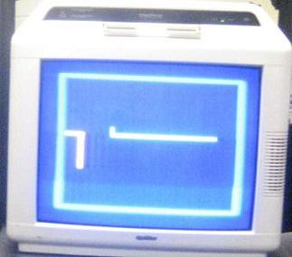 Only three colors are used in our game – one for the border, one for player 1, and one for player 2. We are satisfied with the quality of one of the colors we use in the game, however, the other two colors are not as sharp as we would like them to be. The corner of the wall that player 1 leaves behind at every turn blurs towards the right of the screen, and the border of the game is also a little blurry at the corners. We could not fix this after trying many different modifications to the video generation circuit. The overall image is very stable, and the quality is better than enough for good gameplay and makes the game visually pleasing. 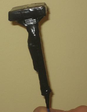
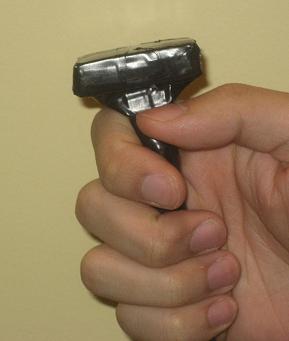 Our controllers were successful in that they reliably perform all the functions that we wanted them to, and the game is playable using them. They were initially too sensitive to be used. We fixed this by decreasing the rate at which the ADC is polled. The controllers are a good size, light, and overall, comfortable to hold on to. Users should be able to play with ease after a few rounds of getting used to the controls. 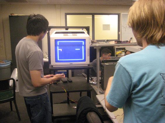 After much trial and error tweaking of game parameters to make the game as playable as possible we arrived at a great success. Our Light Cycle game, while having a bit of a learning curve for the controls, as extremely fun and playable.
|
|
Our final project implementation closely matched our initial proposed design and certainly met our expectations. The Light Cycle game is very playable, our tilt control scheme works exactly as intended, and our color television display is crisp and clear.
The game is very fun to play, and we feel like we accomplished exactly what we set out to do, while learning and having lots of fun in the process.
If we had to repeat our project, however, there are a few things we would do differently. Foremost, we would have ordered our parts earlier. The fact that we still did not decide a week into final projects what chips we are going to need for our color TV prevented us from starting on that part of the project early. This made us nervous and anxious while we were waiting for parts to arrive, since we (correctly) thought that the color video generation would cause lots of headache and frustration. Aside from a few hiccups, the implementation of our color television design went well. While we initially planned on using internal SRAM, we realized that such a heavyweight solution isn't necessary for our Light Cycle game, which only needed a few distinct colors to function correctly. Also, using SRAM would have occupied all the ports of the MCU, but we needed a free port to use for analog to digital conversion. Instead of ordering a different MCU last minute, we decided it would be best to sacrifice the higher quality color image we could have gotten if we used the external SRAM in exchange for a simpler more understandable design that better conforms to our project specifications. Intellectual Property Considerations The Light Cycle game software and the hardware and software for our accelerometer controllers was fully original. Each of these pieces were specified entirely by us and implemented accordingly without any outside sources besides some datasheets. Our video generation design was based on Alan Levy's work at Cornell University while working with Dr. Bruce Land on color video generation. Many aspects of his design, both in hardware and software were modified to better fit our goal. Lastly, as mentioned above, we are fully aware that Tron and Light Cycles are intellectual property of Disney Corporation. The ideas for our game are loosely based on the arcade game that was created over twenty years ago. We do not believe there is any sort of intellectual property violation here due to the age of the original idea and fact that our project only slightly resembles the original. Moreover, our project is one of a purely academic purpose, and we do not intend to distribute it for profit or distribute it at all, in fact. Ethics Our project is in full compliance with the IEEE Code of Ethics. We have ensured that our project is consistent with health and safety standards by ensuring the television signal is high enough quality not to damage players' health due to flicker. We also took extra precaution in designing our controllers in order to ensure they do not pose any sort of electrical hazard to the user. There were meticulously packaged and insulated to guarantee safety. We also avoided any sorts of conflicts of interest by awknowledging our game idea is based on a concept from Tron and by explaining how the similarities are minimal and how they should not cause any intellectual property concerns. Lastly, we took extra care to ensure none of our work is misrepresented and credited anyone from whom we borrowed ideas or designs. Future Extensions The various frameworks and loosely coupled modules that encompass our project can easily be extended to create other color video applications or accelerometer based applications. We invite our readers to build upon our work or use it as a framework for future projects. |
Source Code
|