
Website and Project created by : Jared Frisch and Matt Richwine
Contents
- Introduction
- High Level Design
- Program Design
- Hardware Design
- Results of the Design
- Conclusions
- Appendix A: Code
- Appendix B: Schematics
- Appendix C: Cost Details
- Appendix D: Specific Tasks
- Appendix E: References
Introduction
Our project is a hand-held device that is capable of communicating with any vehicle that uses pulse-width modulation (PWM) data-link layer. Such devices are commonly referred to as On-Board Diagnostic scanners. Vehicles that typically fall into this category are Fords made between 1996 and 2007. In our case, we used a 2003 Ford Mustang as the test vehicle for our device.
The diagnostic information can be displayed on our mobile LCD display with the option of sending the data to a PC running MATLAB for logging and plotting parameters like engine speed, oxygen sensor values, etc. This combines the convenience of a portable self-containted diagnostic tool with the added flexibility of a PC interface for advanced data acquisition.
High Level Design
Our device is designed to be a flexible, capable interface that allows the user to access every parameter that the vehicle’s system has to offer with little or no modification to the program. It is also designed to be expandable for future improvements like the addition of the (Variable Pulse Width Modulation) VPW, ISO 9141, and CAN protocols that are commonly used among other makes.
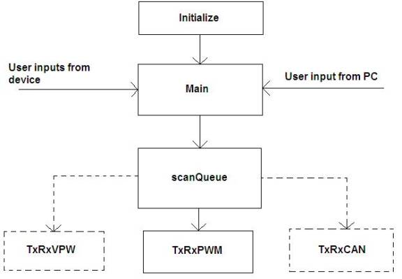
Figure 1: Overall system flowchart
Four routines are responsible for most of the communication to both the vehicle and the PC. The first is the initialize routine that sets the microcontroller port, interrupts, and initializes the LCD and RS-232 port. The routine main controls the rest of the program. Currently, this program keeps a virtual timer and periodically calls the scanQueue routine. However, main could easily be expanded to use the PC to modify the requests made by the device to the vehicle as well as set other display or data acquisition options like one-time scans or continuously looped scans. While main could directly call the TxRxPWM routine, we wanted the functionality of monitoring several different parameters in tandem. To accomplish this, another routine named scanQueue cycles through up to four different data requests. Ultimately, the routine TxRxPWM is called to communicate with the vehicle. As one could imagine, additional functions like TxRxVPW or TxRxCAN could be created for communicating to vehicles of other protocols.
Program Design
The main routine of our program starts with an initialization which sets up all of the ports of the ATmega32 along with all of the program timers and interrupts. The LCD display is also setup during initialize, and a "starting" message is output for the user's awareness. After initializing, main calls scanQueue which stores a series of requests for data that the user wants to monitor. These requests can range from current or past error codes, to vehicle speed, to ignition spark phase. The error codes are four digit numbers that correspond with a particular error in the vehicle's system. An error is indicated when the “Check Engine” light is illuminated on the dashboard. Once the error code is read by our tool, the code can be referenced in a vehicle repair guide or in Society of Automotive Engineers (SAE) documentation, thus facilitating repair of the problem.
The scanQueue function can handle up to four different requests for information. Each call of scanQueue calls another function named TxRxPWM for each different request for information. It is TxRxPWM that handles all communication with the vehicle.
When TxRxPWM is called, it checks a character array that contains the information being requested from the vehicle. A request is specified by two bytes that are appended to a three byte header. For example, a request for engine speed would look like 0x416b10410c in which the first three bytes are the header and the last two bytes specify the parameter to be monitored—in this case, engine speed. From these five bytes, a sixth byte that is used for cyclical redundancy check (CRC) is calculated and appended onto the previous five bytes. The CRC is a more sophisticated parity check used to verify that the data was not corrupted during transmission. The algorithm for calculating the CRC byte is borrowed from www.obddiagnostics.com.Before these six bytes are transmitted according to SAEj1850 PWM specifications, the vehicle’s bus is checked for activity. If the bus is active, then the transmission is delayed. If the bus is idle, then the six bytes are transmitted sequentially. Special symbols mark the beginning and end of a transmission. The start of frame symbol is a thirty-two microsecond dominant value followed by a sixteen microsecond recessive value. Each one of data is transmitted as an eight microsecond dominant value followed by a sixteen microsecond recessive, while each zero is transmitted as the opposite; sixteen microsecond dominant values followed by eight microsecond recessive values.
The data receive portion of TxRxPWM follows immediately after the transmission code. The reply from the car is captured using Timer 1’s input capture function. The bits are then decoded using the same timing scheme described for transmission and then placed into byte form. The data is then parsed via a search for special symbols, headers, and data. When a frame is sent to the car, the car replies with a series of frames of which only one or two are an answer to the request made. The code sifts through all of the vehicle's responses until the reply sought is found. Finally, scanQueue displays the result on the LCD display and sends it to the PC via the RS-232 serial port. The interrupts that control the RS-232 port are courtesy of Bruce Land, instructor of Cornell's ECE 476.
It is worth noting that we are working at the microsecond timescale and attention to timing is critical. For this reason, we disabled all interrupts during transmission, and only turned on interrupts when absolutely necessary. Interrupts were used during the receive routine as they were integral to proper functionality.
Hardware Design
The hardware provides an interface between the TTL logic levels of the microcontroller and the differential PWM bus that uses non-destructive arbitration. The vehicle’s bus is set up such that any one of multiple nodes on the bus can take control of the bus any time the bus is idle. Therefore, each node must monitor the bus to ensure that it is idle before broadcasting a message on the bus. If two nodes happen to begin broadcasting simultaneously, the node with higher priority (as specified by its header bytes) will remain in control of the bus while the node with the lower priority message will cease transmitting and wait until the bus is idle before trying again to broadcast to the bus. As specified in the SAE J1850 documentation, 0V on the positive bus is a dominant symbol while 5V on the negative bus is a dominant symbol.
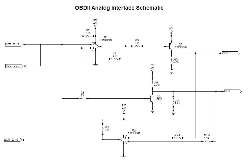
The general idea for the circuit comes from www.obddiagnostics.com. To transmit on the bus, the MCU sends the PWM stream of data out on PORTD.5. Pin D.5 is jumped to pin D.7 which is configured as an input. This feedback ensures that the MCU always knows the state of the bus. The PWM signal is sent to an NPN transistor that pulls the negative side of the PWM bus low when the MCU outputs a high value. Otherwise, the bus is passively pulled high by a 10k ohm resistor. Simultaneously, the MCU output at D.5 is inverted with a comparator and sent to a PNP transistor that pulls the positive side of the PWM bus high. Similarly, the positive side of the bus is passively pulled low by a 10k ohm resistor. When the MCU outputs a low value, each bus is set in its passive state so that other nodes are free to use the bus.
To receive signals from the bus, each side of the bus is fed into a comparator via a 10k ohm resistor. The output connects to the MCU at pin D.6, which is the input capture pin for Timer 1. See Appendix B for the schematic.
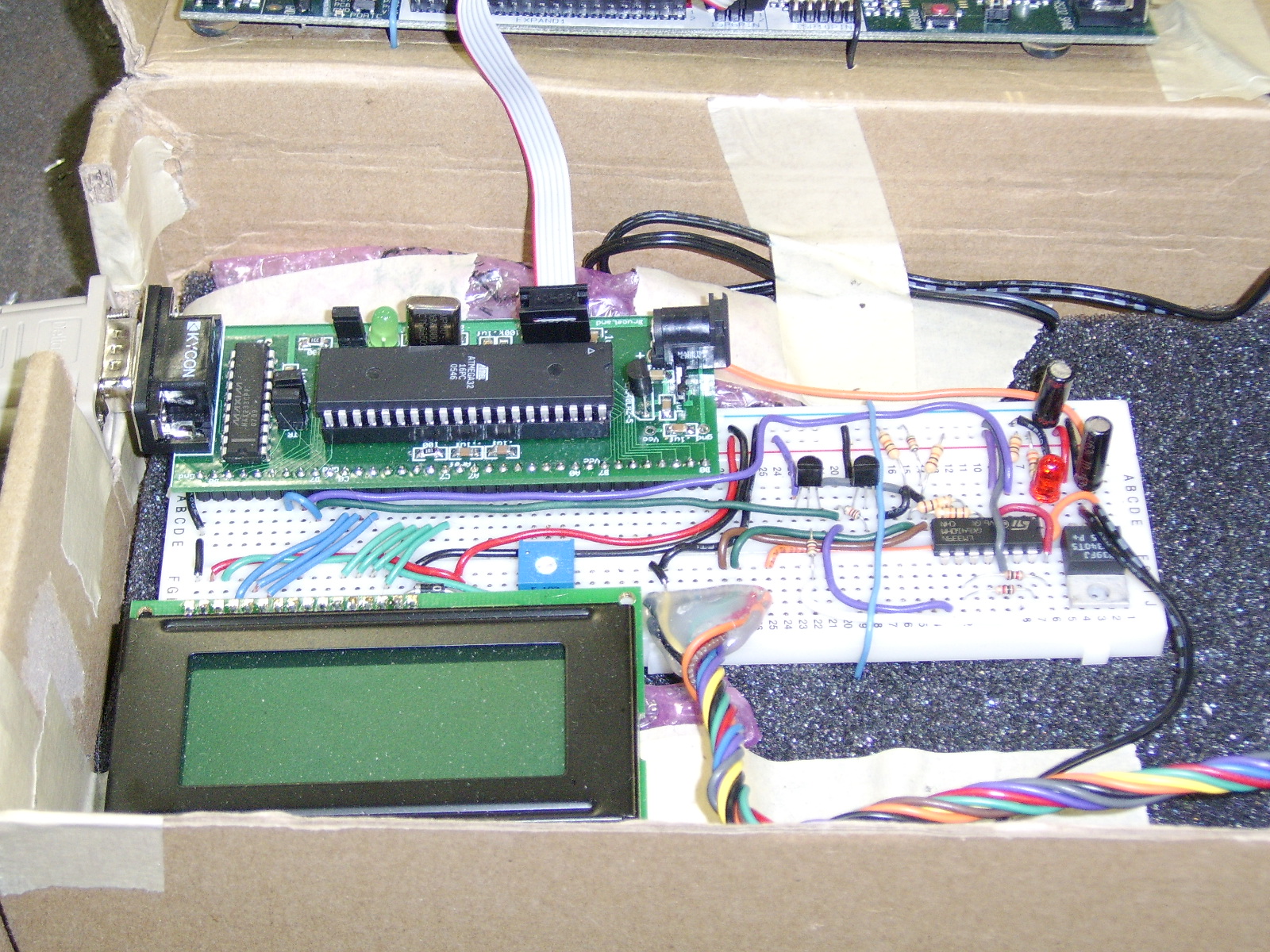
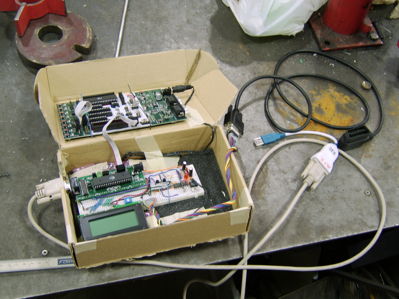
Figure 2: OBDII reader
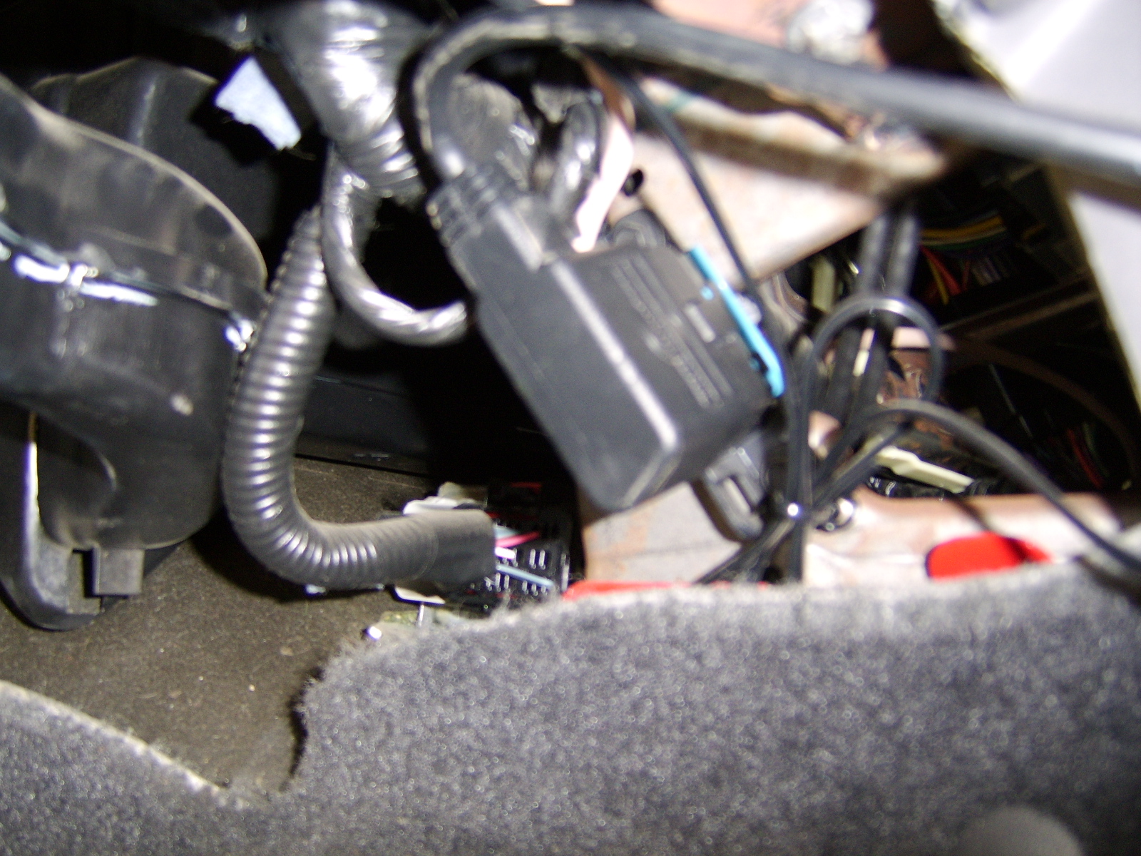
Figure 3: Mustang ECU connection
Results of the Design
Our final project has met and exceeded our expectations from the begining of this course/project. The OBDII reader remained relatively compact and portable, and functions almost exactly as we first predicted. Our code conforms precisely to the SAEj1850 specifications, which provided a relatively easy process of working with Matt's car. All interrupts were kept as simple as possible in order to allow the code to run as efficiently as possible.
Multiple tests have been run on our project with a few different test commands. RPM and engine temperatures have been read with extreme accuracy, and the reader itself appears to obtain correct responses from the car with over a 90% accuracy rate.
Our main safety concern on this project came from the fact that we were interfacing our project with Matt's car. It is always necessary to be vigilant when working around running internal combustion engines in enclosed spaces due to the risk of asphyxiation. To avoid such risks, the project was always worked on outdoors, which alleviated such concerns.
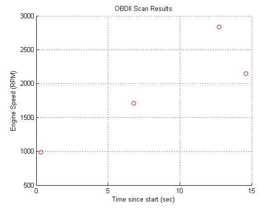
Figure 4: Real time matlab plot of engine speed (RPM) from OBDII reader
Conclusions
In the end, we are extremely happy with the results we obtained. The OBDII reader successfully transmits and receives according to protocol from Matt's Ford Mustang with very low data collision rates. Although we would have liked to have been able to implement VPW and/or CAN protocol, we are more than satisfied with a fully functional handheld PWM OBDII reader with LCD and PC readout.
Anyone looking to expand upon this project, or a future project for us might be to expand this reader to work on all cars with ECU access (not just those with PWM protocol). Another option might be to enlarge the library of built in requests to send to the car beyond those used in our project for proof of concept.
Our design conformed exactly to the SAEj1850 standards, with all communication protocols being designed with these standards in mind. Without strict conformity, the car would not respond to any of our device's requests. The SAEj1850 standard is readily available from the SAE store or engineering library.
Our RS-232 code was taken from the ECE 476 website, and is the only instance of code being taken from the public domain. However, the CRC algorithm and the basic analog circuit were borrowed from www.obddiagnostics.com.
No reverse engineering was used at any time during the creation of our project, and no patent/trademark issues arose. Similarly, no non-disclosures were needed to be signed in the acquisition of any of our sample parts.
There are probably no patent opportunities as most of our hardware and software is already in existance in some form. Our project was more of a proof of conept using the ATmega32 than a new discovery.
By strictly following the protocol setup by SAEj1850 we adhered to all of the IEEE code of Ethics. In our report, all of our claims have been checked to make sure that they are both honest and realistic based on the observed data that we have physically seen and experienced. When possible, unaltered photos and graphs have been added to confirm the validity of our statements. Using our project as a proof of concept, using the Atmega32, we also believe that we have improved our understanding of current technology, and by way of the ECE 476 website will continue to improve the understanding of technology among future generations. In this way, we will assist our current and future colleagues in their professional development along with our own. In our quest to push the boundaries of what has been done with this technology we made sure to never undertake any tasks for which we are not qualified. Doing so ensured that safety was always taken into consideration, and that Matt’s car along with the property of the lab, all avoided injury. We also made certain that no part of our project interfered in any way with the projects of other colleagues in the lab, avoiding conflicts of interest and threats to the development of our colleague’s projects.
Appendix A: Code
ATmega32 code
// ECE476 Final Project: OBDII Reader
// Matt Richwine, Jared Frisch#include <Mega32.h>
#include <Math.h>
#include <stdio.h>
#include <delay.h>
#include <string.h>
// define a new I/O register for easier programming
sfrw ICR1=0x26;
// LCD setup
#asm
.equ __lcd_port=0x15
#endasm
#include <lcd.h> // LCD driver routines
#define LCD_width 16#define begin {
#define end }//*************************************************************
// Instantiate subroutines and their variables
// main's variables
char lcd_buffer[17]; //LCD display buffervoid initialize(void);
unsigned char pgmTimer;void selectCom(void);
void TxRxPWM(void);
unsigned char TxData[5] = {0x61, 0x6a, 0xf1, 0x00, 0x00};
// TxData {h1, h2, h3, mode, PID}
unsigned char TxSOF[1] = {32};
unsigned char TxTimerData[80], TxCRCTimerData[16];
unsigned char byteIndex, bitIndex, bitMask, timerIndex;
unsigned char CRCpoly, CRCreg;
unsigned char checkBus, busBusy, busWasBusy, TxTrial, TxError;
unsigned char OCRloadFlag, TxDone, lastOut;
unsigned char IFR;
unsigned char RxTimerData[200];
unsigned char bData[100];
unsigned char byteData[20];
unsigned char RxTimerIndex, timerIndexRx, lastRxTime, RxDone, RxError,RxTrial,i,sofFlag,dataVal,dataStop;
unsigned int j,dataLoc,dataInc,k,byteCount;
unsigned char ansFrame, shift, tempByte;void gets_int(void);
//RXC ISR variables
unsigned char r_index; //current string index
unsigned char r_buffer[16]; //input string **** converted to int for multiplies
unsigned char r_ready; //flag for receive done
unsigned char r_char; //current character
void puts_int(void);
//TX empth ISR variables
unsigned char t_index; //current string index
unsigned char t_buffer[16]; //output string
unsigned char t_ready; //flag for transmit done
unsigned char t_char; //current charactervoid scanQueue(void);
unsigned char scanCount;
unsigned int headFlag, rpm;
unsigned int PIDa, PIDb, PIDc, PIDd;//**************************************************************
void main(void)
begin
initialize();
selectCom();
while(1)
begin
// run timer at 4mS => do this from OVF interrupt!
// scan keyPad every ~30mS unless transmitting/receiving
if (pgmTimer == 0)
begin
pgmTimer = 250;
PORTD = PORTD ^ 0x04;
scanQueue();
end
//Assign PIDs to be scanned
PIDa = 0x010c;//engine speed
PIDb = 0x0000;//null
PIDc = 0x0000;//null
PIDd = 0x0000;//null
//############################################################
//while(1); //freeze
//############################################################
// write user interface menu (large nested IF?) => calls scanQueue with 4PIDs
end //while
end //main//**************************************************************
void initialize(void)
begin// SET UP PORTS
//PORTA = switches/user input
DDRA = 0x00;
//PORTC = LCD
DDRC = 0xff;
//PORTD.2 blink LED
DDRD = 0xff;
PORTD = ~0x04;
//PORTD.1:0 RS232 with PC
DDRD.6 = 0; //ICP1 Rx from bus
PORTD.6 = 0; //turn off pull-up resistor
//PORTD.5-7 OBD with vehicle
DDRD.7 = 0;// Comm input (jumped to output for feedback)
PORTD.7 = 0; //turn off pull-up resistor
//set up program timer0 for 1 mSec timebase
OCR0 = 250;
TIMSK = 0b00000010; //turn on timer 0 comp-match ISR
TCCR0 = 0b00001011; // prescalar = 64, clear-on-match
pgmTimer = 50; //50mS timer
//set up timer1 for fast PWM at 0.5uS
TCCR1A = 0b01000011; // Setup fast PWM mode, WGM1:0
TCCR1B = 0b00011000;// WGM3:2, prescalar = 8, PWM is OFF at startup
// NOTE: toggle bit 1 of TCCR1B to turn on/off
// Output OC1A is toggled on D.5
// TOP value is OCR1A-- loaded when counter reaches TOP
PORTD.5 = 0;// force low output on start up
//initialize LCD
lcd_init(LCD_width); // set up width of LCD display
lcd_clear();
lcd_gotoxy(0,0); // go to top left
lcd_putsf("Starting...");
//syntax: sprintf(lcd_buffer,"Cap: %3.2f nF",cap);
//syntax: lcd_puts(lcd_buffer);
//initialize RS-232 link
UCSRB = 0x18;//enable serial comm
UBRRL = 103;//9600baud
r_ready=0;
t_ready=1;
//putsf("\r\nStarting...\r\n");//########################################
gets_int();
// syntax: printf("%d\r\n",variable);
// syntax: puts_int();
// syntax: sscanf(r_buffer,"%d",&v); v is an unsigned char
// syntax: gets_int();
// example: cIndex = (r_buffer[1]);
//enable interrupts
#asm
sei
#endasm
end //initialize//==============================================================
// Program Timer Interrupt (turned off during communication)
interrupt [TIM0_COMP] void pgmTimer_comp(void)
begin
if (pgmTimer > 0) --pgmTimer;end
//==============================================================
// Input Capture Interrupt-- receive pulse-width values with 0.5uS resolution
interrupt [TIM1_CAPT] void PWM_receive(void)
begin
RxTimerData[timerIndexRx] = ICR1 - lastRxTime;//record TCNT1 to array via ICR1
TCCR1B = TCCR1B ^ 0b01000000; //XOR edge trigger
lastRxTime = ICR1; //update
if ((timerIndexRx > 198)) RxDone = 1;//signal end of Rx
timerIndexRx++;//move to next place in Rx array
end
//==============================================================
//UART character-ready ISR -- source: Bruce Land
interrupt [USART_RXC] void uart_rec(void)
begin
r_char=UDR; //get a char
UDR=r_char; //then print it
//build the input string
if (r_char != '\r') r_buffer[r_index++]=r_char;
else
begin
putchar('\n'); //use putchar to avoid overwrite
r_buffer[r_index]=0x00; //zero terminate
r_ready=1; //signal cmd processor
UCSRB.7=0; //stop rec ISR
end
end//==============================================================
//UART xmit-empty ISR -- source: Bruce Land
interrupt [USART_DRE] void uart_send(void)
begin
t_char = t_buffer[++t_index];
if (t_char == 0)
begin
UCSRB.5=0; //kill isr
t_ready=1; //transmit done
end
else UDR = t_char ; //send the char
end
//==============================================================
//**************************************************************
void selectCom(void)
begin
//For future expansion
end //selectCom
//**************************************************************
void scanQueue(void)
begin
// Request PIDs a-d from vehicle (PID = 0x0000 is null)
if(PIDa != 0)
begin
TxData[3] = (char)(PIDa >> 8); // Mode
TxData[4] = (char)(PIDa & 0x00ff); //PID
TxRxPWM(); // send to car
//output to RS-232
printf("p");//p is a starting symbol
for (i=0; i<19; i++)
begin
printf("q%x",byteData[(unsigned char)(i)]);//'q' is a parsing symbol
puts_int();
end
printf("r");//r is an ending symbol
//printf("CRC:%x \r\n\n",CRCreg);
//puts_int();
delay_ms(100);
end
//PIDb---------------------------------
if(PIDb != 0)
begin
TxData[3] = (char)(PIDb >> 8); // Mode
TxData[4] = (char)(PIDb & 0x00ff); //PID
TxRxPWM(); // send to car
//output to RS-232
printf("p");//p is a starting symbol
for (i=0; i<19; i++)
begin
printf("q%x",byteData[(unsigned char)(i)]);//'q' is a parsing symbol
puts_int();
end
printf("r");//r is an ending symbol
//printf("CRC:%x \r\n\n",CRCreg);
//puts_int();
delay_ms(100);
end
//PIDc------------------------------
if(PIDc != 0)
begin
TxData[3] = (char)(PIDc >> 8); // Mode
TxData[4] = (char)(PIDc & 0x00ff); //PID
TxRxPWM(); // send to car
//output to RS-232
printf("p");//p is a starting symbol
for (i=0; i<19; i++)
begin
printf("q%x",byteData[(unsigned char)(i)]);//'q' is a parsing symbol
puts_int();
end
printf("r");//r is an ending symbol
//printf("CRC:%x \r\n\n",CRCreg);
//puts_int();
delay_ms(100);
end
//PIDd-----------------------------------
if(PIDd != 0)
begin
TxData[3] = (char)(PIDd >> 8); // Mode
TxData[4] = (char)(PIDd & 0x00ff); //PID
TxRxPWM(); // send to car
//output to RS-232
printf("p");//p is a starting symbol
for (i=0; i<19; i++)
begin
printf("q%x",byteData[(unsigned char)(i)]);//'q' is a parsing symbol
puts_int();
end
printf("r");//r is an ending symbol
//printf("CRC:%x \r\n\n",CRCreg);
//puts_int();
delay_ms(100);
end
headFlag=0;
if(byteData[0]==0x41 && byteData[4]==0x0c) headFlag=1; //check for correct headerrpm = (((unsigned int) byteData[5]<<8) | ((unsigned int) byteData[6])); //find rpm from A and B of data
rpm = (rpm>>2); //divide by 4if(headFlag==1)
begin
lcd_gotoxy(0,2); // go to 3rd line
sprintf(lcd_buffer,"RPM: %d rpm",rpm); //print rpm to LCD
lcd_puts(lcd_buffer);
end
else
begin
lcd_gotoxy(0,2); // go to 3rd line
lcd_putsf("Tx Err: no data");
end
end //scanQueue//**************************************************************
// Transmit data and immediately prepare to receive response
void TxRxPWM(void)
begin
//TxData contains five bytes: {h1, h2, h3, mode, PID}
lcd_gotoxy(0,1); // go to 2nd line
lcd_putsf("Transmitting...");
// Form 80 character array of timings for TxData bytes, calculate CRC byte
// CRC algorithm reference: B. Roadman at http://www.obddiagnostics.com/obdinfo/info.html
byteIndex = 0;
bitIndex = 0;
timerIndex = 0;
CRCreg = 0xff;
while(byteIndex < sizeof(TxData))// sift through bytes
begin
bitMask = 0x80; //start mask at first bit
while(bitMask != 0)// sift through bits
begin
if (bitMask & TxData[byteIndex])
begin
TxTimerData[timerIndex] = 16;//active level
TxTimerData[(unsigned char)(timerIndex + 1)] = 32; //passive level
timerIndex = timerIndex + 2;
//Calculate CRC...
CRCpoly = 0x1c;
if (CRCreg & 0x80) CRCpoly = 0x01;
CRCreg = ((CRCreg << 1) | 0x01) ^ CRCpoly;
end
else
begin
TxTimerData[timerIndex] = 32;// active level
TxTimerData[(unsigned char)(timerIndex + 1)] = 16;// passive level
timerIndex = timerIndex + 2;
//Calculate CRC...
CRCpoly = 0x00;
if (CRCreg & 0x80) CRCpoly = 0x1d;
CRCreg = (CRCreg << 1) ^ CRCpoly;
end
bitMask = bitMask >> 1;// move to next bit
end//while
byteIndex++;
end// header & data while
CRCreg = ~CRCreg; //CRC value//-----------------------------------------------------------
// Create Timing array for CRC byte
bitIndex = 0;
timerIndex = 0;
bitMask = 0x80; //start mask at first bit
while(bitMask != 0)// sift through bits
begin
if (bitMask & CRCreg)
begin
TxCRCTimerData[timerIndex] = 16;//active level
TxCRCTimerData[(unsigned char)(timerIndex + 1)] = 32; //passive level
timerIndex = timerIndex + 2;
end
else
begin
TxCRCTimerData[timerIndex] = 32;// active level
TxCRCTimerData[(unsigned char)(timerIndex + 1)] = 16;// passive level
timerIndex = timerIndex + 2;
end
bitMask = bitMask >> 1;// move to next bit
end// CRC while
//------------------------------------------------------------
// Check if bus is idle
TIMSK = 0; // turn off all other interrupts
TxTrial = 0;
busBusy = 1;
TxError = 0;
busWasBusy = 0;
while(busBusy)//attempt to get idle bus
begin
if(TxTrial > 20)//if 0 attempts have been made
begin
TxError = 1;
break;
end
busBusy = 0; //reset busy flag
checkBus = 0;
while(checkBus < 40)// check if PWM bus is idle for >200uS
begin
if(PIND.6 == 1)
begin
busBusy = 1;//see if bus is high
busWasBusy = 1;
end
delay_us(5); // wait, then check again
checkBus++;
end
TxTrial++;
/*
if((busWasBusy==1) && (busBusy==0)) //Avoid transmitting too soon after the bus opens
begin
delay_ms(1);
busWasBusy = 0;//clear flag
busBusy = 1;
end
*/
end
if(TxError != 0) //if there's an error
begin
lcd_gotoxy(0,2); // go to 3rd line
lcd_putsf("Tx Err: bus busy");
end
//--------------------------------------------------------------
// Transmit TxData on idle bus
TxDone = 0;
while(!TxDone)
begin
timerIndex = 0; //start at the beginning of data timer arrays
OCR1A = 64; //preload high time for SOF
lastOut = PIND.7; //get starting value of output
OCRloadFlag = 0;// reset for new frame transmission
PORTD.5 = 0; //force output to start at zero
TCCR1A = 0b01000011; // Setup fast PWM mode, WGM1:0
TCCR1B = 0b00011010;// turn on timer 1 clock
//------------------Tx SOF
while(timerIndex <1)
begin
if(PIND.7 != lastOut) //output has been toggled
begin
OCR1A = TxSOF[timerIndex]; // load up next value
lastOut = PIND.7; //update lastOut
timerIndex++; // move to next element
end
end
//------------------ Tx Header and Data
while(timerIndex < 81)
begin
if (PIND.7 != lastOut)//output has been toggled
begin
OCR1A = TxTimerData[timerIndex-1]; //load next timing value
lastOut = PIND.7;
timerIndex++;
end
end
//------------------- Tx CRC
while(timerIndex < 97)
begin
if (PIND.7 != lastOut)//output has been toggled
begin
OCR1A = TxCRCTimerData[timerIndex - 81]; //load next timing value
lastOut = PIND.7;
timerIndex++;
end
end
delay_us(16);
TCCR1B = 0b00011000; //turn off timer 1
TxDone = 1;end// while TxDone
//--------------------------------------------------------------------
// RECEIVE CODE
// Use TCCR1 to set up WGM, etc. for inpur capture mode on ICP1 (PORTD.6)
TCCR1A = 0b00000000;
TCCR1B = 0b11000010; //7-noise / 6-edge (rise = 1)
//Look for response frame
ansFrame = 0;
RxTrial = 0;
while(!ansFrame)
begin
RxDone = 0;
RxError = 0;
// Run input capture ISR
timerIndexRx = 0; //start at beginning of Rx array
lastRxTime = 0; //init last value
TIMSK = 0b00100000;//enable input compare interrupt
//wait for data to come in
while(!RxDone)
begin
if((TCNT1 - ICR1 > 160) & (timerIndexRx > 20)) RxDone = 1;
end
TIMSK = 0b00000000;//disable input compare interrupt
//------------------------------------------------
// Decode timings --> bits --> bytes
dataStop=0;
sofFlag = 0;
tempByte = 0;
shift = 0;
byteCount = 0;
j=0;
dataLoc=0;
dataVal=0;while(!dataStop)
begin
if(sofFlag==1) //check for ones,zeroes, and end of data window times (uS): 13-21,28-37
begin
if((27<RxTimerData[dataLoc]) && (RxTimerData[dataLoc]<38) && (12<RxTimerData[dataLoc+1]) && (RxTimerData[dataLoc+1]<22)) dataVal=0;//condition for zero
if((12<RxTimerData[dataLoc]) && (RxTimerData[dataLoc]<22) && (27<RxTimerData[dataLoc+1]) && (RxTimerData[dataLoc+1]<38)) dataVal=1;//condition for one
if((28<RxTimerData[dataLoc]) && (RxTimerData[dataLoc]<36) && (RxTimerData[dataLoc+1]==0)) //check for last bit as zero
begin
dataStop=1;
dataVal=0;
end
if((12<RxTimerData[dataLoc]) && (RxTimerData[dataLoc]<20) && (RxTimerData[dataLoc+1]==0)) //check for last bit as one
begin
dataStop=1;
dataVal=1;
end
// Put data in byte form
if(shift>7)
begin
shift = 0;//reset shift
byteData[byteCount] = tempByte;//store byte
tempByte = 0;//clear tempByte
byteCount++;
end
tempByte = tempByte | (dataVal << (7-shift));
shift++; //increment shift amount
//check for correct frame
if((byteData[0] == 0x41) && (byteData[1] == 0x6b) && (byteData[2] == 0x10) && (byteData[4] == TxData[4]))
begin
ansFrame = 1;
end
if(RxTrial > 6) ansFrame = 1;
if (dataLoc > 197)//safety jump out
begin
dataStop = 1;
RxError = 1;
end
dataLoc=dataLoc+2;
end//if(sofFlag=1)
//Look for SOF symbol-- window times (uS): 60-70,28-37
if(sofFlag==0)
begin
if((59<RxTimerData[j]) && (RxTimerData[j]<71) && (27<RxTimerData[j+1]) && (RxTimerData[j+1]<38)) //check for SOF
begin
sofFlag=1;
dataLoc=j+2;
end
end//if(sofFlag=0)
j++; //j places in RxTimerData before SOF is found
end//while(dataStop)
RxTrial++;//ansFrame timeout monitor
end//while(ansFrame)
//-----------------------------------------------------------
// check CRC of received frame
CRCreg = 0xff;
byteIndex = 0;
bitMask = 0x80;
while(byteIndex < 13)
begin
while(bitMask != 0)// sift through bits
begin
if (bitMask & byteData[byteIndex])
begin
CRCpoly = 0x1c;
if (CRCreg & 0x80) CRCpoly = 0x01;
CRCreg = ((CRCreg << 1) | 0x01) ^ CRCpoly;
end
else
begin
CRCpoly = 0x00;
if (CRCreg & 0x80) CRCpoly = 0x1d;
CRCreg = (CRCreg << 1) ^ CRCpoly;
end
bitMask = bitMask >> 1;// move to next bit
end//while(bits)
if(CRCreg == 0xc4) break;
byteIndex++;
end//while(bytes)
TCCR1B = 0b00011000; //Turn off timer1 from receive
PORTD.5 = 0; // Force output low after receive
TIMSK = 0b00000010; // turn on program timer interrupt
// Report Errors
if (RxError != 0)
begin
//lcd_gotoxy(0,2); // go to 3rd line
//lcd_putsf("Rx Err: bad data");
endend //TxRxPWM
//*****************************************************************************
// -- non-blocking keyboard check initializes ISR-driven
// receive. This routine merely sets up the ISR, which then
//does all the work of getting a command.
//source: Bruce Land
void gets_int(void)
begin
r_ready=0;
r_index=0;
UCSRB.7=1;
end//**********************************************************
// -- nonblocking print: initializes ISR-driven
// transmit. This routine merely sets up the ISR, then
//send one character, The ISR does all the work.
// source: Bruce Land
void puts_int(void)
begin
t_ready=0;
t_index=0;
if (t_buffer[0]>0)
begin
putchar(t_buffer[0]);
UCSRB.5=1;
end
endMatlab code to interface with ATmega32
%===========================================================
% ECE476 Final Project: OBDII Reader
% Matt Richwine mpr32
% Jared Frisch jrf42
%===========================================================%=====clean up any leftover serial connections==============
clear all
try
fclose(instrfind) %close any bogus serial connections
end
close all % close all figures
%=====open a serial connection===============================% Setup Figure
figure(1)
hold on
grid on%escape option
choice = menu('To quit, click...','Quit');% Loop call to RS-232
time = 0;
RxDone = 0;
while(RxDone == 0)
if (choice == 1)
RxDone = 1;
end
if (index == 1)
t0 = clock;
end
[PID,value] = scanOBD();
Ctime = etime(clock, t0);
if (value~=1)
plot(Ctime,value,'ro')
end
end% %===========================================================
% % ECE476 Final Project: OBDII Reader
% % Matt Richwine mpr32
% % Jared Frisch jrf42
% %===========================================================%=====serial communication=============================
%read1 = 0
%while(read1<20000)
% read1 = fscanf(s)
%end
%fprintf(s,'Hello');
% fprintf(obj,'format','cmd') writes the string using the format specified by format.
% format is a C language conversion specification. Conversion specifications involve the %
% character and the conversion characters d, i, o, u, x, X, f, e, E, g, G, c, and s.
% Refer to the sprintf file I/O format specifications or a C manual for more information.function [PIDdec, value] = scanOBD();
A = zeros(34,1);% init receive vector
PIDdec = 2;
value = 1;%=====open a serial connection===============================
baudrate = 9600;
s = serial('COM6','baudrate',baudrate);%,'terminator',0);
%terminator reads the port until an ASCII character desgined as the terminator is reached
fopen(s)% Receive latest transmission
c = fread(s,1,'uint8')
if (c== 'p')%112
A = fread(s,34,'uint8')
end% Re-format for integer operations
for i = 1:34
if (A(i) < 70)
out(i) = A(i) - 48; %capture numbers of hex
end
if ((A(i) > 70) && (A(i) < 103))
out(i) = A(i) - 87; %capture letters of hex
end
if (A(i) > 102)
out(i) = A(i) + 0;
end
end% Reset data
h1 = zeros(1,2);
h2 = zeros(1,2);
h3 = zeros(1,2);
mode = zeros(1,2);
PID = zeros(1,2);
d1 = zeros(1,2);
d2 = zeros(1,2);
d3 = zeros(1,2);
d4 = zeros(1,2);%----------------------------------------------------------------
% Parse transmission
h1(1) = out(2);
h1(2) = out(3);
%out(4) = 'q'
h2(1) = out(5);
h2(2) = out(6);
%out(7) = 'q'
h3(1) = out(8);
h3(2) = out(9);
%out(9) = 'q'
next = 11;% mode
if (out(next + 1) == 113) %possible parse symbol at (next + 1)113
mode(1) = 0;
mode(2) = out(next);
next = next + 2;
else
mode(1) = out(next);
mode(2) = out(next + 1);
next = next + 3;
end% PID
if (out(next + 1) == 113) %possible parse symbol at (next + 1)
PID(1) = 0;
PID(2) = out(next);
next = next + 2;
else
PID(1) = out(next);
PID(2) = out(next + 1);
next = next + 3;
end% data byte 1
if (out(next + 1) == 113) %hidden zero transmission
d1(1) = 0;
d1(2) = out(next);
next = next + 2;% next first is 12
else
d1(1) = out(next);
d1(2) = out(next + 1);
next = next + 3;% next first is 13
end% data byte 2
if (out(next + 1) == 113) %possible parse symbol at (next + 1)
d2(1) = 0;
d2(2) = out(next);
next = next + 2;
else
d2(1) = out(next);
d2(2) = out(next + 1);
next = next + 3;
end% data byte 3
if (out(next + 1) == 113) %possible parse symbol at (next + 1)
d3(1) = 0;
d3(2) = out(next);
next = next + 2;
else
d3(1) = out(next);
d3(2) = out(next + 1);
next = next + 3;
end% data byte 4
if (out(next + 1) == 113) %possible parse symbol at (next + 1)
d4(1) = 0;
d4(2) = out(next);
next = next + 2;
else
d4(1) = out(next);
d4(2) = out(next + 1);
next = next + 3;
end%---------------------------------------------------------
%determine which mode, PID
MODEdec = 16*mode(1) + mode(2); %mode value as a decimal
PIDdec = 16*PID(1) + PID(2); %PID value as a decimal
PIDdecif (PIDdec ~= 12)
PIDdec = 2;
endif (MODEdec == 65)
if(PIDdec == 12)
value = (d1(1)*(16^3) + d1(2)*(16^2) + d2(1)*16 + d2(2))/4;
fprintf('\nEngine Speed: %d RPM',value)
end
% switch(PIDdec)
% case(2)
% fprintf('\nDTCs')
% value = 1;
% case(5)
% value = d1(1)*16 + d1(2) - 40;
% fprintf('\nCoolant Temperature: %d C',value)
% case(12)%0c
% value = (d1(1)*(16^3) + d1(2)*(16^2) + d2(1)*16 + d2(2))/4;
% fprintf('\nEngine Speed: %d RPM',value)
% case(13)%0d
% value = d1(1)*16 + d1(2);
% fprintf('\nVehicle Speed: %d km/h',value)
% case(17)%11
% value = (d1(1)*16 + d1(2))/255;
% fprintf('\nThrottle Position: %d',value)
% end
end
PIDdec
value
%dataOut = [PIDdec, value];%=====write an excel file===================================
%Note that a Lotus file is actully written because
%Matlab cannot currently write an Excel file.
%Excel will read this format
%This version appends a date/time string to each file name
% wk1write([pathname,filename,datestr(datevec(now),30)], [PlayFreq',PlayAmp',OutAmp',OutPhase'])% %=====close the serial port=================================
fclose(s)
Appendix B: Schematics
Figure 5: Overall anlaog schematic
Appendix C: Cost Details
- LCD display- $18
- STK500 programming board (previously owned)
- ATmega32- $8
- ATmega32 socket- $2
- White board-(previously owned)
- LM339- $2
- Max233CPP- (sampled)
- Custom PC board- $5
- RS232 connector- $1
- J1962M Right Angle to DB9F cable- $9.95
- USB-Serial Dongle-$18
- Total Cost- $63.95
Appendix D: Specific Tasks
Jared Frisch
- Receiver Code Design
- Gui Code Design
- Testing Code
- Writing Report
- Website Design
Matt Richwine
- Transmission Code Design
- Hardware Design
- Gui Code Design
- Testing Code
- Writing Report
Appendix E: References
- http://www.obddiagnostics.com/obdinfo/info.html
- maxim-ic.com
- SAEj1850 Surface Vehicle Standard: Class B Data Communications Network Interface
- Bruce Land