
Help Quit Watch
By: Nicholas Creely (nbc5) & Eric Chang (emc47)
| High Level Design | Program Design | Hardware Design | Result of Design | Conclusion | Appendix | Reference | |
Introduction:
The Help Quit Watch is a watch that smokers can wear to help them quit smoking.
The Help Quit Watch contains a smoke detector that detects whenever the smoker smokes and plays an encouraging clip to help the smoker stop. It then records statistics about the smokers habit. In addition, since it replaces the typical wrist watch, it also keeps and displays time and also has an alarm function.
Project Inspiration:
The project was actually inspired by a friend of the group, Helen. Helen had learned in class that most smokers fail to quit because of the lack of reinforcement and support. This has prompted various hot lines that smokers can call when they are having difficulties quitting, however, this is requires the smoker themselves to take action before they are reminded of their goal. This is where our project can come in. As a wrist watch, the user can always wear the watch without any additional hassle, but if they do smoke, they will be automatically reminded and supported. The main reason why we chose this project was that it not only challenged the skills we had learned in class, but also to apply these skills by building something very practical and useful. With the incredible large amount of smokers in the world, believe that our tool will help make the world a better place.
Overall Concept:
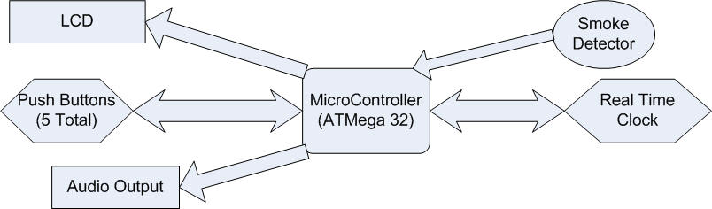
The Help Quit Watch can be separated into three main components: the user interface, smoke detector and power management. These three components all feed into the microcontroller, which then handles the information and communicates to the other appropriate components. First, the user interface consists of 5 push buttons, an LCD and audio speakers. The 5 buttons, 4 on the STK 500 and 1 external, allow the user to wake the watch up, view recorded statistics, view and set time and alarm. The Help Quit Watch would be able to display time, keep track of the time since that last time the user had smoked, keep track of the number of times they had smoked in the past week week, and have one alarm. The LCD displays the information that the user selects to view and the audio component either sets the alarm off or gives the encouraging message when the smoke alarm is set off.
The second is the smoke detector. The smoke detector is homebuilt using an IR emitter and detector. The voltage from the detector adjusts according to the amount of light being detected. This voltage is then compared to a reference voltage, high when the detector voltage is higher than the reference and low otherwise.
The third part is power management. As a wrist watch, power consumption is critical, thus it is important to not have the microcontroller on when there are no calculations needed. Thus, our group implemented an Real Time Clock that has memory for an alarm. Thus, the microcontroller is asleep under normal operating conditions and is only turned on if one of three contingencies happen: the user wants to view/change the time/statistics/alarm, smoke has been detected, or the alarm goes off. When the Mega32 is in sleep mode, the RTC keeps track of the time allowing us to significantly decrease the power consumption. Below is an overall diagram:
Standards:
The UL-217 standard specifies the requirements that must be met by smoke alarms. Our rudimentary smoke alarm does not meet this standard. However, it is not necessary for our smoke alarm to meet this regulation because this standard is meant for smoke alarms for fire safety in residential units whereas our smoke detector is not being used for a residential setting.
Overall Design:
The software for this lab has four main components. The most important component, task1(), is responsible for the scheduling and execution of many of the watch’s most important features. These features include the MCU’s time keeping, the handling of a smoke detection, the reading and handling of the four STK push buttons used, the LCD output of the MCU, and the handling of putting the MCU to sleep. Another important aspect of the software is the handling of the three external interrupts into the MCU. The software also is responsible for the voice outputs for both the watch telling the user not to smoke and for the wake up alarm. Finally, the software is responsible to keep the MCU’s time synchronized with the RTC’s time.
Task 1:
Task 1 runs every 100 ms and makes up the heart of the Help Quit Watch’s software program. Each iteration of task 1 first reschedules itself to run in the next tenth of a second. The task also keeps track of the time so that the MCU does not have to constantly communicate with the RTC while it is awake. Time is kept by sequentially iterating tenths of seconds, the unit digit of seconds, the ten digit of seconds, and then so on all the way up to the unit and ten digits of years.
Task 1 then looks for a smoking flag which would indicate that the smoke detector interrupt has gone off. If this happens, it will record the time for the purpose of being able to calculate the time since the last time the user has smoked and also increments the number of times smoked this week. However, we realize that the same cigarette could cause the smoke detector to cause an interrupt multiple times, so we implemented a one minute timer to prevent the same cigarette from being counted as multiple times smoked. The smoking flag will also cause a speech clip saying, “Don’t smoke. It’s bad for you,” to play.
Task 1 is also responsible for the handling of most of the Help Quit Watch’s user interface. This includes reading the inputs from the STK 500’s four push buttons and outputting to the LCD. The functions of the four push buttons are as follows:
-Button 0: Set Time/Alarm On
-Button 1: Set Alarm Time/ Alarm On
-Button 2: Time Since Last Smoke/ Hours
-Button 3: Number of Times Smoked This Week/ Minutes
If Button 0 and Button 1 are pressed together, it will turn the alarm on or off and the LCD will read “Alarm On” or “Alarm Off” accordingly. If Button 0 is pressed at the same time as Button 2, the watch’s time will be increased by one hour. If Button 0 is pressed with Button 3, the watch’s time will be increased by one minute. Pressing Button 1 along with Button 2 or 3 will increase the time of the alarm by one hour or minute respectively and will output “Alarm at <new time>”. Pressing Button 2 alone will display the amount of time it has been since the last time the user has smoked. This is done using a helper function called lastSmokeCalc(). Pressing Button 3 alone will display the number of times the user has smoked during the current week. These push buttons all use Port A of the MCU.
Finally, Task 1 is responsible for detecting whether or not the MCU should be put into Power-Down mode. After a minute of inactivity, the variable sleepin will have a value of 0 and the microcontroller will be put to sleep. Every time the user interacts with the watch, however, the timer will be reset to sixty seconds.
External Interrupts:
Our project uses three external interrupts into the microcontroller. These three interrupts are the smoke detector going into INT0, the push button going into INT1, and the RTC interrupt going into INT2. The software for the watch uses an ISR to deal with each of these three interrupts. Each of these ISRs will wake the microcontroller up from Power-Down mode if needed. If the ISR wakes the microcontroller up, it will also load the time to the MCU from the RTC. Each interrupt also has a unique effect in addition to this. The smoke detector interrupt is responsible for setting the smoking flag high when it is run so that task 1 will know that smoke has been detected. The push button interrupt is responsible for turning off the wake up alarm if it is running. The RTC interrupt first determines which of the two RTC alarms as gone off. Alarm 0 on the RTC is used in our program as the watch’s user-settable alarm. If this goes off, the watch will start the PWM to make it say “Wake Up!” until the user stops it. Alarm 1 is set to go off at midnight at the first day of every week. The purpose of this is to reset the counter for number of times smoked in the week.
Speech Output:
The speech in this project was handled in a very similar manner to the way it was handled in Lab 2. Speech is produced by updating OCR0 every timer 0 overflow. If the PWM is on, the output to OCR0 will be determined by one of two helper functions that synthesize a voice output from one of two DPCM tables. The function voice0() will play a clip saying, “Don’t smoke. It’s bad for you,” every time smoke is detected. The function voice1() will play a clip saying “Wake Up” until the push button is pressed stopping it.
The sound clips were originally recorded from this website. This sound clip was synthesized using the techniques listed on the ECE 476 website.
Communication with
the RTC:
One of the most vital parts of this lab is keeping the
times on the microcontroller and RTC synchronized.
The communication with the RTC was done using SPI.
Writing to the RTC was done by first sending the address being written to
and then sending the data. For
example, writing to the seconds register in the RTC would look like:
SPIout = (seconds10<<4) | (seconds & 0x0f);
PORTB.4 = 1; //CS high begins load
junk = spi(Wseconds);
junk = spi(SPIout);
PORTB.4 = 0; //CS low ends load
To read from the RTC, we first had to send the address to
be read from and then take in the value at that address and interpret it.
For example, reading from the seconds register in the RTC would look
like:
PORTB.4 = 1; //CS high begins load
junk = spi(Rseconds);
SPIin = spi(0x00);
PORTB.4 = 0; //CS low ends load
seconds = SPIin & 0x0f;
seconds10 = SPIin>>4;
Communications with the RTC happen under three different circumstances. The first is the initialization of microcontroller program, when the RTC’s time must be initialized by writing to each of its registers. The second situation where communication must happen is when the user changes either the time, alarm time, or turns the alarm on or off. When this happens, the change must be written to the RTC. Finally, the time must be read from the RTC when the MCU comes out of sleep mode. These communications will assure that the MCU and RTC times will match each other.
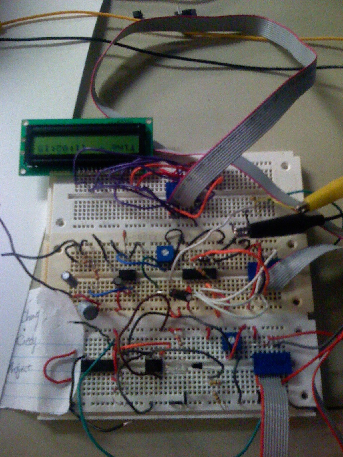
The hardware design can be separated into five main components: the smoke detector, the RTC, the LCD, the audio output and the push button. The overall final product looked like:
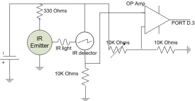
At first we wanted to reverse engineer a commercial smoke detector that we had purchased at Walmart, however, after attempting this for a few days and consulting TA's we decided to build our own smoke detector. We decided use a simple IR emitter and detector combination as the basis of the smoke detector. The IR detector has an voltage output that reflects how much light it detects, around 2V with no obstructions and closer to 0V as less and less light is detected. Using this, the idea is to compare the voltage of the detector to a reference voltage that is calibrated such that if any of the light is obstructed from the detector, the voltage will drop below the reference voltage and the signal will go low. This low signal is then connected to INT1 on portD, thus allowing the smoke detector to externally interrupt the Mega32 and wake it up from sleep mode. Below is a circuit diagram of the smoke detector.
The RTC that was selected to use was the DS1305 from digikey. The DS1305 is a serial alarm real-time clock that provides clock/calendar information accessed through the serial interface. The clock/calendar information contains seconds, minutes, hours, day, date, month and year information. The serial port on the ATMega 32 was through port B, thus the RTC was connected to this port. The RTC was connected to the MCU with the suggested circuit from the data sheet, which is pasted below:
 The crystal required is a 32.768 kHz
clock, which was also purchased from digikey. The INT0 pin was connected to
interrupt 2 on the Mega32 (PORTB2). PIN9 on the DS1305, the SERMODE pin was
connected to Vcc to enable SPI mode.
The crystal required is a 32.768 kHz
clock, which was also purchased from digikey. The INT0 pin was connected to
interrupt 2 on the Mega32 (PORTB2). PIN9 on the DS1305, the SERMODE pin was
connected to Vcc to enable SPI mode.
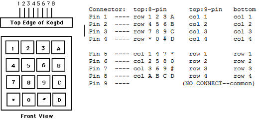
The LCD circuit used was the same as used in previous labs, thus the LCD circuit was built according to lab specifications. The keypad was connected to PORTC. Below pasted are the directions:
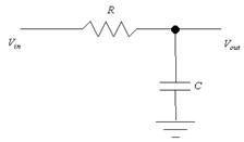
At first, we wanted to improve upon the design of the audio from lab and build our own speaker circuit. In the end, we decided on the LM386, a low voltage audio power amplifier as the center piece of the audio circuit. However, during the process of building the circuit, due to our own carelessness or accidentally wiring to a wrong port, we blew both of our power amplifiers 2 days before the demo. Because of this, we resulted to plan B, which was to use the same audio circuit was we did in previous labs and use the black and white TV as our speaker. The audio circuit was the same as used by previous labs with a simple RC filter. The circuit diagram is pasted below, with a 10k resister and a 20 nF capacitor.
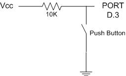
Lastly was an additional push button that would be connected to an interrupt pin on the Mega32, thus allowing the user to wake the Mega32 up to view statistics as well as view or change the time and alarms. All the other push buttons were the ones on the STK 500, however, because this push button had to be connected to the interrupt on PORT D, it was much easier to build an external push button. Since the interrupt is active low, we designed the circuit below, which causes the voltage on PORT D.3 to go low when the button is pushed, activating the interrupt and waking up the Mega 32.
Our final design was quite successful. All the parts came together successfully creating a usable device to help smokers quit. The push buttons worked and allowed the user to easily adjust the time, set the alarm, turn the alarm on/off, and view statistics. The RTC would keep time when the Mega32 was asleep, and was able to wake the Mega32 up to play the alarm sound when the alarm when off. The smoke detector also worked and was able to wake the Mega32 up to play the encouraging message to help stop the user from smoking. In fact, we accomplished more in this lab than we had originally set. When we first decided to build the Help Quit Watch, some TA's suggested that our project may be overly simple and suggested that we attempt to build our own smoke detector to make the project more challenging. In addition, our professor suggested that we implement some sort of power management system so that we don't have the Mega32 running the entire time. In the end, we were able to expand our projects to not only include the functions from our original idea of the Help Quit Watch, but also to have our own home built smoke detector as well as an RTC connected to the Mega32 such that the Mega32 is only on when the user is interacting with our project.
The speed of execution for our code was not an issue as the human reaction is much slower than any of the calculations required for the Help Quit Watch.
This project does not involve any projectiles, harmful radiation, or biological sensors. Furthermore since this prototype will not be an actual wrist watch implementation, there would be limited safety concerns. However, when designing this into an actual wrist watch, there would be more safety concerns. As the wrist watch would be worn, there should be a heat test to ensure that under no conditions does the microcontroller heat to a temperature harmful to the human skin. Furthermore, there should be quality that all wires are enclosed to prevent and accidental voltage shocks to the user.
Since there are no wireless components in this project, there would not be any interference problems.
One of the biggest human factors with the usability of the help quit watch is that they will not wear the watch, limiting its potential benefit. We hope that with the implementation of basic wrist watch functionality, it would help increase the use of the help quit watch. This makes it easily to incorporate the Help Quit Watch as part of peoples daily accessories. The interface would be very user friendly at it is mostly automatic with 5 simple push buttons to set time and display additional information. The interface design is based off of common wrist watches, thus requiring minimal user training for use and no user input required for start up.
Our end product worked surprisingly well. The Help Quit Watch was able to not only correctly reflect the functionalities a normal wrist watch would have, but also successfully served its purpose of supporting any user who may want to quit smoking. However, we do realize that there are many area's of improvement and that our final product is still far from what is possible to send to a manufacturer. Since our main focus for the final project was to have the functionalities of the Help Quit Watch developed, if we had more time, we would have liked to work on improving the size. Our end project is incredibly large, with an STK500, 3 bread boards and an LCD the size of a hand, this was nowhere near the size of a normal wrist watch. Next time, without the need to learn how to use an RTC or how to user the serial interface, we could work on fitting all the components on a PCB board, that may later be shrunk to an IC and actually fit into the size of a wrist watch.
One thing that we might have done to improve our project would to be to use five external push buttons rather than using four of the STK 500’s push buttons. The STK push buttons can sometimes be hard to press and therefore are not as user friendly as external push buttons. We used the STK’s push buttons primarily due to budget concerns, however when we were done we realized that using the external push buttons would not have affected our budget very much at all.
One final thing we would probably do differently with this project would be with the audio output. We were unable to produce an output that could be played by a stand-alone speaker and instead had to use the speaker from a black and white television. This, of course, would not be practical in a final design for a watch. We believe that we might have burnt out audio amplifier chips while attempting to build an amplifying circuit and did not have time to find a replacement.
Since all the code was developed by ourselves, there are not any intellectual property considerations. The only code that we had reused was code from previous labs, which were also developed by us. We did not reverse engineer anything designs nor were any of the parts in our project sampled. We do believed that there may be a patent opportunity for our design. There are many commercial tools in the market to try and help smokers quit, but none like the one we have designed. We believe that with some professional help and additional work on the project, this potentially could become a patented commercial product to help the millions of smokers quit.
We followed the IEEE Code of Ethics throughout the development of our project. We made sure to always wear safety glasses and away from other groups when working with soldering tools. When we were testing our smoke detector, we always made sure to alert near by fellow classmates and TA's of what we were doing. However, after realizing the disruption of having smoke in the lab even after an early warning, we decided to user paper for our tests and demo of the smoke detector. This decision was also made since it prevented other groups from easily detecting if they had accidentally burned something, thus we decided that it was unsafe to produce any smoke intentionally in lab. We made sure to be fair to everyone and to give credit to anyone who contributed to the design of the project, including friends that are not involved in this class. Through online readings, TA and professor help, discussions and sometimes trial and error, we have improved our understanding of various technologies, especially the microcontroller. Additionally, we were glad to accept criticism about our project early on and took on advice of potential ways of expanding our project. We continued to seek advice from our TA's by keeping them up to date on our status and goals. Even in the rush to finish our project, we tried hard not to be disrespectful to any of our TA's or fellow classmates and offered any assistance or advice we could when requested. In addition to following the code of ethics during the execution of the project, we also believe that our project is of great ethical character. Smoking is one of the biggest problems in society and we feel that our project can help make a difference. Hopefully with more projects like our own, we can eliminate smoking from our society.
We do not have any legal considerations since all the code was written by ourselves and we did not use any parts that are regulated by agencies like the FCC.
Schematic:
All the hardware schematics are attached in the hardware section along with descriptions of how they were used.
Code:
You can download the code here.
Budget:
| Item | Quantity | Price/Per | Total Price |
| STK 500 | 1 | $15 | $15 |
| White Board | 3 | 6 | $18 |
| Power Supply | 1 | 5 | $5 |
| Mega 32 | 1 | 8 | $8 |
| LCD | 1 | 8 | $8 |
| B/W TV | 1 | 5 | $5 |
| RTC | 1 | 5.06 | $5 |
| 32KHz clk | 3 | 0.36 | $1 |
| LM386 | 2 | 0.94 | $2 |
| Commercial Smoke Detector | 1 | 4.99 | $5 |
| Total Cost: | $72 |
Tasks:
In general Nick Creely worked more on the software, while Eric Chang worked more on the hardware and the report. Nick developed the code communication between the smoke detector, the push buttons and the RTC. He also developed the code to sleep and externally wake up the Mega32. Eric Chang mainly worked on building the smoke detector, the audio circuit, the external push button circuit, the LCD circuit and the circuit for the RTC. Eric Chang also wrote most of the final report. However, these were general divisions. Nick also helped Eric with both the RTC circuit, the smoke detector circuit and the report. Eric also helped Nick develop some of the code for the LCD, push buttons and the external interrupt code. Both team members assisted each other and contributed to each others parts as well.
All the code in our project was written by ourselves, however, we could like to reference a previous 476 project (Multi-Zone Fire Alarm System) for the smoke detector. It was a great reference to help us get started quickly on how to build our own smoke detector.
Thanks to Helen Zhou for inspiring our project idea. Thanks to Bruce Land for his assistance throughout lab and providing supplies in the lab. Thanks to all the TA's for keeping the lab open and all their advice.
DataSheets:
DS1305 - Serial Alarm Real Time Clock
ATMega32 - Microcontroller
SER3205 - 32.768 kHz Clock
LM386 - Low voltage audio power amplifier