
The Trumpet MIDI Controller allows trumpet players the freedom of synthesizing from and composing on their native instrument.
"The Elevator Pitch"
The Trumpet MIDI Controller allows trumpet players the freedom of synthesizing from and composing on their native instrument.
The Trumpet MIDI Controller combines custom hardware and software with the Yamaha Silent Brass pickup mute to convert any standard trumpet into a fully functional MIDI controller and MIDI pass through device for up to 16 channels.
Thomas Craig (twc22)
Bradley Factor (bef23)
High Level Design
Project Inspiration | Project Concept | Music Theory | Background Mathematics | Design Overview
Project Inspiration
Robert Moog created one of the first modular voltage-controlled music synthesizers in 1964. However, unlike the synthesizers created by competitor Don Buchla, Moogs synthesizers used a piano-style keyboard for the majority of user input. Since then, most synthesizers have also featured a piano-style keyboard. The motivation for this design is mostly pragmatic. Pianos have a very large range with up to 88 keys. Neglecting hand motion for reaching largely spaced notes, all of the notes require similar amounts of effort to play, and therefore the entire range is readily available. This is useful to both performers and composers.
Despite the universal nature of the piano-style keyboard, some instruments differ sufficiently to make keyboard input too impractical or unnatural, a prime example being drums. Piano notes are mainly defined by pitch and duration. Although duration is similarly defined for drums, the type of drum played typically predefines the pitch, rather than how the drum is played. There are also key mechanical differences between how one plays a keyboard and how one plays drums, which make trying to use one to imitate the other awkward at best.
Although there has been some branching out in synthesizer design, in particular to drum synthesizers and electric guitars, the predominant modern synthesizer still uses a keyboard. This also appears to be the case in ECE 476 final projects, especially with regard to MIDI controllers. Our desire to produce a unique and challenging project in combination with Brads ownership of a trumpet and music workstation led to the idea, and eventual selection, of a trumpet-based MIDI controller.
During the concept development phase, we discovered two marginally similar products on the market, the Morrison Digital Trumpet (MDT) and the Yamaha EZ-TP Trumpet. The MDT is marketed as a brass wind controller which supports 10 octaves of notes, does not require any lip buzzing, and can be substituted as a performance instrument. This is accomplished through breath sensing with a piezoelectric transducer, photodiode sensing of valves and additional buttons for octave selection, and output to a MIDI sound module. The MDT sells for $1,955 which places it in the mid-range price of MIDI instruments and mid to high-range price for an actual trumpet. The Yamaha EZ-TP is similar except that the main input is humming or whistling in addition to valve presses. The EZ-TP is difficult to locate, however its selling price is about $350, placing it in the very low-end pricing for both synthesizers and trumpets.
Project Concept
Our primary goal is to create a functional MIDI controller that unlike the MDT and the EZ-TP can be played the same as a typical trumpet. This means that it must be capable of playing every note within the standard range of a trumpet based on the same user inputs given to a normal trumpet. MIDI stands for Musical Instrument Digital Interface, a standard designed for transmitting instrumental events, such as beginning or stopping a note, rather than sampled music waveforms.
Music Theory
The sound of a trumpet is produced through coupled resonance between a mouthpiece and the rest of the trumpet. The trumpeter blows air through closed lips which makes a buzzing sound in the mouthpiece. This then sets up a closed-open standing wave in the air column within the trumpet. The output pitch is selected from a range of overtones, natural resonances of the trumpet, by changing lip tension and aperture, known as embouchure. Typical modern trumpets are constructed with three piston valves which increase the tubing length when engaged. The first, second, and third valves lower the trumpets pitch by a whole step, half step, and one-and-a-half steps respectively. Adjustments of the embouchure, and valve selection known as fingerings, make the trumpet able to play all twelve pitches of Western music.
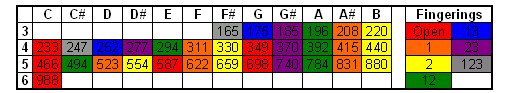
Notes with played frequencies in Hz and associated fingerings.
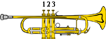
Valve numbering.
Fingerings select overtone series. They are denoted by Open, 1, 2, 12, 23, 13, and 123 which indicate which valves are depressed, with Open denoting no valves depressed. The standard range of a trumpet is from F#3 to C6. Between limitations imposed by fingerings and the range of the trumpet, this means that there are between 2 and 6 notes per overtone series. It is worth noting that the overtone series begins with the first overtone rather than the fundamental.
The most common type of trumpet, and the type that will be used in the Trumpet MIDI Controller, is a Bb trumpet. This means that when playing a note written as a C, the actual frequency output is that of a Bb. Similarly, all other notes produced by the trumpet are a whole step lower than the written note.
A final but important note regarding music theory and trumpet mechanics, air pressure applied by the trumpeter controls the volume of the sound output of the trumpet. However, higher notes are more difficult to play, so the softest version of a given note may be louder than most cases of another lower note.
Background Mathematics
The principal mathematical tool used for this project is the Fast Fourier Transform (FFT), which converts a sampled signal from time to frequency domain. In other words, the FFT provides the amplitude of corresponding frequency signals which, when added together, will give you the originally input sample sequence. This allows us to determine which frequencies are dominant in the sampled signal.
Also important to this project, but beyond the scope of explanation here, is the Nyquist-Shannon Sampling Theorem. Particularly important results from this theorem are aliasing and the Nyquist frequency.
Design Overview
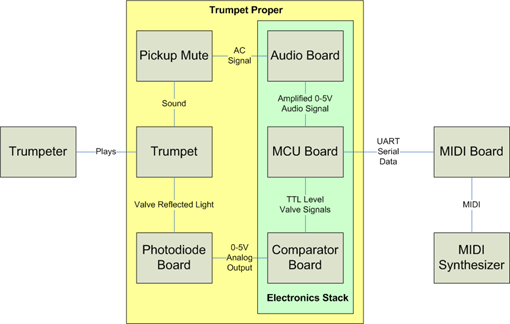
Hardware Interconnect Overview.
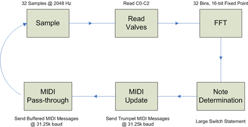
Software Flow Diagram.
Implementation
Hardware | Mechanical | Software | Note Determination | MIDI Protocol
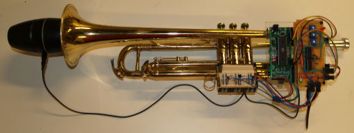
The fully assembled trumpet viewed from the side.
Hardware
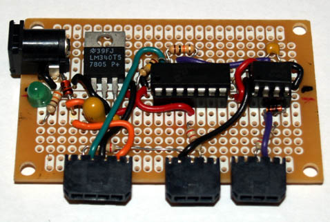
MCU Board
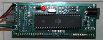
The Microcontroller, or MCU, Board is the center of the Trumpet's electrical design. The MCU Board is a modified ECE476 Prototype Board which hosts an Atmel Mega32 running at 16 MHz. It is responsible for sampling audio data, valve presses, and MIDI commands, processing that data, and outputting the corresponding MIDI commands. The modifications to the board include:
1. A 2x2 Molex Microfit 3.0 receptacle has been mounted in the location intended for a DB-9 connector. TTL-level transmit and receive signals from the MCU's UART are routed to this connector, along with ground and Vbattery. This connector is called the MIDI connector.
2. A small rework wire has been run from 5V to the AREF pin.
Audio Board
The audio board provides biasing for the BJT within the condenser microphone as well as amplification of the audio signal with an AD623 instrumentation amplifier. The biasing is provided by a resistor voltage-divider (R3 and R4). This signal is then capacitively coupled through C2 to a ~2.5V DC offset such that the signal will be able to swing rail-to-rail on a single 5V supply. Vref and V- are both referenced to a 2.5V DC level such that the AC signal is amplified, since the amplifier's output voltage is A*(V+-V-) + Vref, and so the output can swing rail-to-rail as well. Using a 5.7 kOhm gain resistor sets the gain to be about 21 which works well for our signals which are between tens of millivolts and a couple hundred of millivolts. The audio board connects to A0 for channel 0 of the microcontrollers ADC as well as power and ground.
Photodiode Board
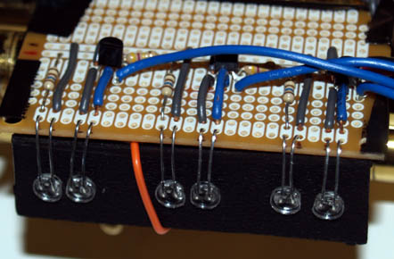
The photodiode board uses pairs of LED to determine which valves are depressed at a given time. One of the diodes in each pair is set up to emit with a constant 20mA current while the other diode is tied between ground and the base of an NPN BJT such that incident light upon the photodiode produces a voltage on the BJTs base. Since each BJT is configured as a common emitter amplifier, the base voltage is amplified and inverted on the output. Each channel is identical. The Photodiode Boards signal and power connects directly to the Comparator Board.
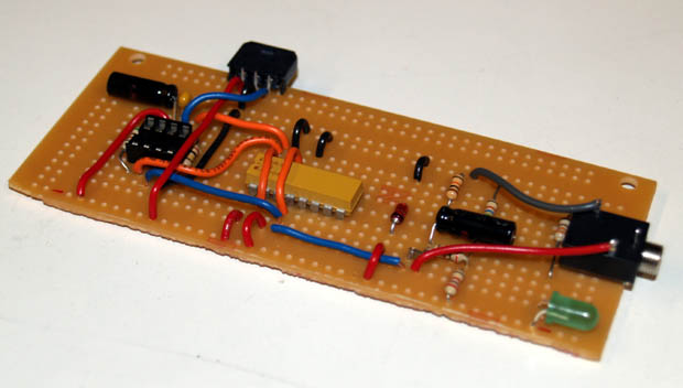
Comparator Board
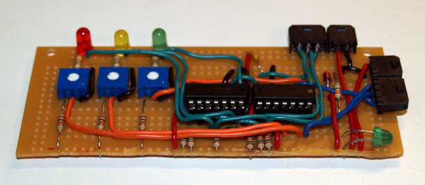
The comparator board is responsible for converting the amplified voltage outputs of the Photodiode Board to TTL levels based on adjustable thresholds. This was accomplished with an LM3302 quad comparator with voltage references provided by three different 10k potentiometers, one per channel/valve. A 74LS32 quad OR IC is used as a current buffer for driving an LED for each channel, such that a red, yellow, or green LED illuminates when valves 1, 2, and/or 3 are pressed. The photodiodes are positioned such that the reflected light is greatest when the valves are not depressed and by depressing the valves the valve gets too close to the LEDs to reflect a significant amount of light. The thresholds were set empirically by adjusting the reference until the light went off while depressed, and then the thresholds were brought up slowly until the light was on strongly. The Comparator Board connects to pins C0 through C2 on the MCU and receives power from the Audio Board.
MIDI Board
The MIDI board connects both MIDI IN and MIDI OUT to the MCUs USART. MIDI OUT is fairly simple, requiring only two resistors to convert the voltage output to the necessary 5 mA current loop. MIDI IN is a little more complicated as the MIDI standard requires MIDI IN to be isolated. For reasons still unknown to us, however, the output rise time of the 6N138 opto-isolator was very slow, on the order of 30 microseconds, despite it being a standard part for MIDI input which should have a better than 2 microsecond rise time. To bypass this issue, we used an MCP6544 5V rail-to-rail comparator with the negative input biased to 0.5V to improve rise time to orders of magnitude better than we needed. The MIDI IN and MIDI OUT connectors and cables are interchangeable such that the different gender cables can be swapped to support different MIDI devices. The MIDI Board connects to the UART via the MCU's D0 and D1 pins. Also, the MIDI board has a barrel receptacle for receiving battery power which is connected through a safety diode to the MCU's unregulated supply via the MIDI cable. This allows powering both boards from a single power supply.
Mechanical

The assembled electrical stack.
The Trumpet MIDI controller is assembled in three main components, the photodiode board, a plastic electronics mounting plate, and a MIDI Board and battery pack belt clip.
The photodiode board is electrical tape wrapped for insulation and then wire tied to the valve casing of the trumpet. A 1/8 thick ABS/PVC mounting plate was cut and drilled for the LEDs in order to hold them within the valve housings.
The plastic electronics mounting plate holds the MCU board and a stack of the Audio Board and the Comparator Board. Three standoffs were attached by way of hot glue to the MCU board for mounting. Additional standoffs and spacers were added similarly to the stack for structural support. The stack and the MCU board are screwed into the acrylic plate using #4-40 screws. Anti-static foam padding from sample containers was affixed to the back of the plate to provide a non-marring and compressible mounting surface for the plate. The mounting plate is also secured to the trumpet by way of wire ties.
A belt clip was designed for the MIDI board and battery pack using an 1/8 cut tab of ABS/PVC and two standoffs. The 6 AA battery holder is then affixed to the assembly by zip ties to the MIDI Board.
Software
Initialization
The program begins by initializing all hardware peripherals and critical global variables. Peripherals are configured as follows:
When not in debug mode, the USART is configured for 8-N-1 operation at MIDI standard 31.25 kbaud. Since 31.25 kbaud is not compatible with standard computer UARTs, the USART is configured for 38.4 kbaud operation to facilitate debugging during debug mode. Also, the USART_RXC receive interrupt is enabled for receiving MIDI Pass-Thru messages.
Timer1 is configured to trigger the TIM1_COMPA interrupt at 2.048 kHz as a sampling clock.
The Analog to Digital Converter is configured to sample channel A0 and trigger the ADC_INT interrupt when sample conversion is complete.
Finally, after all else is complete, global interrupts are enabled.
Sampling
Every time the Timer1 interrupt fires, it checks the status of a global flag named gotsamples. If the flag is true, it means that the sample buffer is already full and awaiting servicing by the main loop, so the ISR exits. Otherwise, when the sample buffer is not yet full, an ADC conversion is triggered.
When a conversion completes and the ADC_INT interupt fires, the new sample is stored in the sample buffer and a counter is incremented. Then, if this counter is equal to 32, the gotsamples flag is set to 1 to indicate that the sample buffer is full and stop ADC triggering. Therefore, ADC sampling is not resumed until the gotsamples flag is cleared by the main loop.
Sample Processing
The main loop constantly polls the gotsamples flag and runs task_fft when the flag goes high. This task immediately reads the current valve state from PORTC0..2 to determine the current fingering. Then, the 8:8 16-bit real-only Fast Fourier Transform (fft) of the new samples is computed and stored, along with the sum of the absolute value of all samples. This sum is later used for volume determination. Then, since task_fft no longer needs the current sample values, it clears the gotsamples flag so that sampling can resume. This is intentionally done as soon as possible because the sampling period is longer than the run time of task_fft (except for in pathological cases) and therefore is the most limiting factor for program throughput.
Next, the software proceeds to determine what, if any, note is currently being played. The note is computed based on the current fingering and fft results by the algorithm described in Note Determination.
MIDI Update
Based on the newly determined note, the note determined the previous cycle, and the note last sent out over MIDI, a decision is made about whther or not to change the current MIDI note. There are four possible cases here:
1. If a note is currently playing over MIDI, and it is decided that a new note should be playing, a Note Off message is sent for the current note, followed by a Note On message for the new note.
2. If a new note should be playing and there is not a note currently playing, only a Note On message is sent.
3. If a note is currently playing and it is decided that no note should play, then only a Note Off message is sent.
4. If there should be no change in note then neither a Note On or Note Off message is sent.
Next, if the note most recently detected is the same as the note currently being played over MIDI, a Volume Controller message is sent to adjust the synthesizer's volume to match that which the user is currently playing.
MIDI Pass-Thru
Finally, the software checks to whether or not any messages have been received on the MIDI-IN port which must be forwarded to the MIDI-OUT port. If any complete messages are found, they are copied out over MIDI-OUT. To enable concurrent receipt and forwarding of MIDI messages, the serial receive interrupt stores incoming bytes into a ring buffer. Therefore, the main loop keeps printing out MIDI messages until the ring buffer has been exhausted, at which point task_fft exits and waits for gotsamples to go high again. The ring buffer logic is complicated slightly because MIDI messages can be (and usually are) multiple bytes long and must be transmitted contiguously. Unfortunately, while MIDI messages due have a start indicator, their is no trivial end-of-message indicator short of parsing the protocol. Therefore, the only simple way to know whether or not you have received a complete message is if you have received the start byte of the following message. Since there is no guarantee that a message will follow soon after a prior message, this has the potential to create huge (potentially infinite) delay between when a message is received and transmitted by the microcontroller. To work around this, we assume that any message will be completely received within one period of task_fft, and so we consider any message complete whose start indicator was received on the previous iteration of task_fft.
Note Determination
At it's most basic, the process of note determination is a matter of finding characteristics of one note that allow you to tell it apart from the others. First, we note that while there 31 notes total, we can trivially reduce the choice set to a maximum of 6 at any given time based on the fingering. Therefore, we need only differentiate notes from others of the same frequency based on frequency content. By analyzing FFT results, we see that we can tell notes apart based on whether or not they have certain frequency components. To illustrate this, the two plots below show FFT results for the two notes, F#3 and C#4, which are played with the 123 fingering.
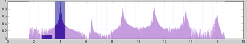
F#3 Frequency Content: Hi-resolution vs. processed 16-bin
C#4 Frequency Content: Hi-resolution vs. processed 16-bin
In the background of these plots is a high resolution FFT of the input note while the foreground contains a plot of the fraction of times over many time periods that a particular bin of the 16-positive-bin FFT result exceeded a threshold of 0.8 times the maximum bin in that result. We see that the bins which exceeded threshold 100% of the time correspond to the highest peaks of the high resolution FFT. Comparing the plots for each note, we see that there are three bins which are always and only present in a particular note. Therefore, checking for the presence of any one of those bins tells you which note is being played. To improve accuracy in situations such as these, we could also use a voting system which checks for the presence or absence of multiple indicators.
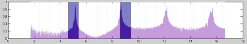
Unfortunately, not all fingerings are quite so straightforward. Below, we see the result of the same 16-bin FFT algorithim from above when applied to the notes of fingering 1.
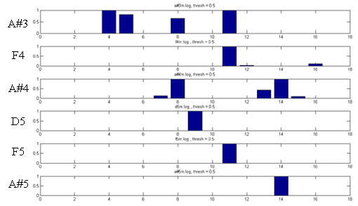
Fingering 1 Frequency Content
Based on this plot's results, we see that most, but not all, notes can be fairly trivially distinguished by the method above. However, that approach does not allow us to distinguish notes F4 and F5 reliably because the always-present and always-absent bins are common between the two. In this case, we find it instructive to look at the distribution of FFT bin values over a large number of runs. Below are such distributions, normalized as before, for notes F4 and F5. The plots for each note correspond to low, medium, and high volume, as indicated. The green circles correspond to the minimum and maximum values encountered, the red plus signs indicate the 25th and 75th percentiles, and the blue x marks the median value.
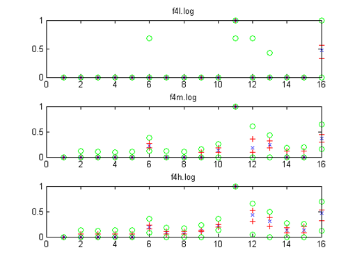
F4 Frequency Distribution
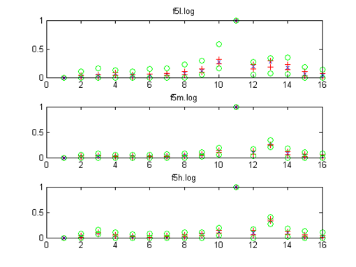
F5 Frequency Distribution
This distribution proves informative because it provides new less-certain indicators that were not evident before. For example, F5 will typically have a smaller bin 6 than F4, and F5 will typically have a much smaller bin 16 than F4. Based on this, we see that it is possible to set per-bin normalized thresholds which will each typically yield the right answer. However, because of the overlap in distributions between notes, each indicator will sometimes be wrong. In this case, we can decrease probabity of an incorrect decision through the use of a voting algorithm that makes a decision based on whether or not a certain number of indicators agree.
MIDI Protocol
For our purpose, only a few MIDI messages are of interest. Each message begins with a status byte, which has its first bit set, followed by some number of data bytes, which have their first bit cleared. The first nibble of each status byte is a command code and the second nibble is the channel, allowing for 16 channels.
Note On: CMD = 0x9
This message tells the synthesizer to begin playing a key (KK) with a velocity (VV), where each key corresponds to a note and velocity is equivalent to how quickly a note was hit. KK is the first data byte, VV is the second data byte.
Note Off: CMD = 0x8
This message tells the synthesizer to stop playing a key (KK) with a velocity (VV), where each key corresponds to a note and velocity is equivalent to how quickly a note was released. KK is the first data byte, VV is the second data byte.
Volume Controller: CMD = 0xB
This sets the current output volume, on a scale from 0 to 127. First data byte is 7, second is the desired volume.
Patch Change: CMD = 0xC
This sets the current patch for this channel. Patch 57 is the General Midi Trumpet. First data byte is the desired patch.
Turn Off All Notes Controller: CMD = 0xB
This message turns off all notes. First data byte is 123, second is 0.
Results
The speed and accuracy of the Trumpet MIDI Controller is excellent considering the speed of the microcontroller and the limited sampling rate. There is some noticeable latency; however, after two days of using the Trumpet MIDI Controller, it became practically unnoticeable. The Controller does exhibit some note dropouts from time to time as notes are promoted to higher octaves when they should not be or remain unvoiced due to thresholding. Initial note velocity appears to be accurate so long as the note sounded is clean. There is excellent dynamic range in the volume adjustment while a note is playing, allowing for expression between pianissimo and forte; playing to fortissimo may cause unintentional promotion of notes to higher octaves. There is a direct correlation between the quality of the notes played and the accuracy of the Trumpet MIDI Controller. MIDI pass-through appears to work perfectly as there is no noticeable phase jitter during playback.
Several audio demos are provided below. All of the demos are audio recordings of the sound output of a Korg Triton LE music workstation controlled via MIDI with the Trumpet MIDI Controller. The only audio editing performed on the clips was normalization to adjust the volume to better listening levels.
This demo illustrates typical solo playing with a trumpet patch.
This demo illustrates the dynamic range of the Trumpet MIDI Controller and how a trumpeter can easily play crescendos and decrescendos.
This demo illustrates solo playing with an orchestral patch.
This demo illustrates playing with an accompaniment by way of the MIDI pass-through capability of the Trumpet MIDI Controller. In this demo, a computer is outputting the accompaniment over ten MIDI channels. All messages from these ten channels are read in by the Controller and output with the additional messages generated by the Controller itself.
This demo illustrates using the MIDI pass-through capability with three channels of accompaniment.
The 32 bin FFT takes 1.95ms to execute. Independent of sending any MIDI messages, our main loop, between sampling, FFT, and selection logic, requires 18.5ms to execute. This means that we can send up to 16 messages per loop, which is sufficient throughput for volume adjustment messages and MIDI pass-through functionality. If this number is exceeded, the main loop will execute slower, leading to greater latency between trumpet sounding and MIDI output.
The use of an on-board battery power pack, rather than an AC power adapter, ensures that the user is not exposed to any high voltages. The use of an opto-isolator on the MIDI IN input, as specified by the MIDI standard, further ensures that the MIDI Trumpet Controller remains isolated, both for the safety of the device and the user. The Silent Brass mute attenuates the trumpet sound output substantially; however, we advise people in close proximity to the bell of the trumpet to wear ear protection.
The MIDI Trumpet Controller does not emit signals that will interfere with other projects.
The Trumpet MIDI Controller is best utilized and enjoyed by individuals who are capable and trained in playing the trumpet. Other individuals capable of supporting the weight of the Trumpet MIDI Controller and exerting themselves through exhaling may use the Trumpet MIDI Controller without risk, but may not receive the maximum enjoyment possible.
Conclusion
Expectations
The MIDI Trumpet Controller has met and exceeded our expectations. We were able to produce a device that relies only on sound input and valve sensing, rather than additional buttons, to determine the note that the user is playing. The Controller reliably transmits MIDI messages, implementing Note On, Note Off, Patch Change, and Volume. Our initial project proposal did not include plans for dynamically adjusting volume during a note, however we have been pleasantly surprised by the results. Rather than implement a composer mode as suggested in our initial proposal, we implemented MIDI pass-through and used Make Musics Finale software for MIDI recording and playback.
Although the MIDI Trumpet Controller performed quite well, there are some things we would change in the next revision.
1. Sampling Rate: With a 2048Hz sampling rate, our frequency determination extends to 1024Hz which is sufficient to capture the first overtones of notes, but not additional overtones of higher notes. These additional overtones would be useful in making note determination easier. However, this would require a 64 bin FFT, so we would either need to accept the greater latency, use a faster processor, or somehow optimize the FFT algorithm.
2. Filtering: We appeared to be seeing aliases of overtones of higher notes. At first, we suspected the aliases might be useful in note determination; however, they actually made note determination more difficult. To fix this issue, we would use a low-pass filter with a cutoff at the top of our frequency range, most likely made using filter blocks from Linear and Linears Filter CAD program.
3. Construction: Despite all of the prototype boards used, the entire design could easily be condensed onto one small PCB that would fit on the valve casing of the trumpet. This small PCB could then be installed in a leather valve casing protector, for a very compact and easy to use product.
4. User Interface: Right now, we essentially have none. We would want to add an LCD and some buttons and switches to allow for functionality such as changing patches on the Controller and transposing notes up and down.
Standards
The MIDI Trumpet Controller conforms to the MIDI 1.0 spec through implementation of a 5mA current loop, opto-isolation on the MIDI IN connection, and transmission of proper MIDI commands at 31.25k baud.
Intellectual Property Considerations
The only external code used for the MIDI Trumpet Controller is the FFT Library from the ECE 476 website. No reverse-engineering was performed. No non-disclosure agreements were signed. The most likely patent opportunities for the Trumpet MIDI Controller are in the algorithm used for note determination, or any custom hardware developed in the future to aid in note determination.
Ethical and Legal Considerations
All decision and actions taken in the development of the Trumpet MIDI Controller were and are consistent with the IEEE Code of Ethics. The decision to use a pickup mute, rather than a microphone with an unattenuated trumpet, illustrates our acceptance of the responsibility of making decision consistent with the safety, health, and welfare of the public. No factors arose that might have endangered the public or the environment; however, had they arisen, we would have promptly disclosed them. The Trumpet MIDI Controller was developed as part of a non-profit effort; regardless, all real or perceived conflicts of interest were avoided. All of our claims and estimates are based on the data that we accumulated and testing that we performed during development. No bribes of any sort were accepted during this project. We believe that the Trumpet MIDI Controller has improved the understanding of brass acoustics in combination with analog and digital electronics as well as signal processing. Many skills were learned and improved during the course of this project, with the understanding that we are students rather than trained and salaried professionals. We received and accepted constructive criticism from other groups in the lab, and did our best to offer our own constructive criticism in turn.
There are no applicable legal consideration to the Trumpet MIDI Controller.
Appendix
Code Listing
Schematics
Budget
Solder Board (6) $2.50 x 1: $2.50
Custom PC Board $5 x 1: $5.00
Mega32 x1: $8.00
DIP Socket: $0.50 x 7: $3.50
Header: $0.05 x 16: $0.80
Radio Shack Board Perf Board: $2.00 x 2: $4.00
Quad Comparator 296-17223-5-ND: x1 $0.53
Opto-Isolator 6N138QT-ND: x2 $1.60
Male DIN-5 CP-1050-ND: x1 $1.23
Female DIN-5 CP-1150-ND: x1 $1.32
Narrow View RED LED 67-1122-ND: x8 $4.56
Battery Holder BH26AAW-ND: x1 $1.21
Analog AD623 In-Amp AD623ANZ-ND: x1 $4.50
Assorted Microfit 3.0 Connectors: Sampled
Maxim MAX233ACPP x1: Sampled
Assorted Resistors: ECE476 Lab
10k Potentiometers: ECE476 Lab
Assorted Capacitors: ECE476 Lab
Assorted LEDs: ECE476 Lab
74LS32 Quad-OR x1: ECE476 Lab
MCP6544 Quad-Comparator x1: Sample
BJT 2N3904 x3: ECE476 Lab
Total: $38.75
Tasks
Thomas: Primary MCU Coder, Matlab Algorithm Development, MIDI Board, MAX233 Board, MCU Board Rework
Brad: Trumpet player, Matlab Algorithm Development, Audio Board, Comparator Board, Photodiode Board
References and Acknowledgements
Our FFT is based on and only slightly customized from the real-only code from ECE476 DSP on Mega32.
Our MIDI transceiver is based on the design from http://www.borg.com/~jglatt/tech/midispec.htm
