OBDII Project
Our goal for this project was to build an OBD-II compliant device that would communicate with any OBD-II enabled car and read back real time data as well as perform basic performance testing and diagnostics.
If you've ever had to take your car into the shop because of the dreaded "Check Engine" light, you can have the same appreciation for this project as we did. Since 1996, all cars sold in the United States have been required to implement the On-board diagnostics (OBD-II) standard. This standard allows mechanics and repair technicians to communicate with a vehicle's on-board computer and read out data from it, including why the check engine light is on. Commercial OBD-II readers are available but offer limited functionality and are often expensive. Plus they are not nearly as cool as the project we decided to build.
High Level Design
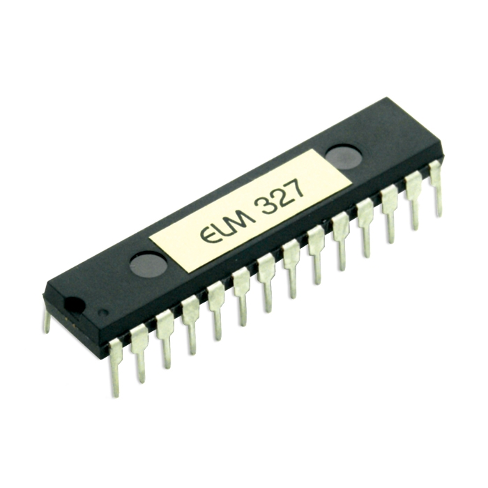
We began our project based around a chip that is designed to handle OBD-II interpretation, the ELM327 from ELM Electronics. This chip has the capability to transmit in any of the various transmission standards implemented by different car manufactures, and was the basis for the hardware design of our project. It converts the different vehicle communications formats into ASCII strings that are transmitted using RS232 serial. Many custom OBD-II projects exist on the web and we pulled ideas from these designs, which are listed in our references section. For the most part though, our hardware design was based off of directions contained within the ELM327 datasheet and the other various components that we purchased such as the MCP2551 (CAN Transceiver) and our 4-line HD44780 compliant LCD screen.
We used menu structure ideas from our security system lab as the basis for some of our software, as well as how to implement the UART communications between the microcontroller and the ELM327.
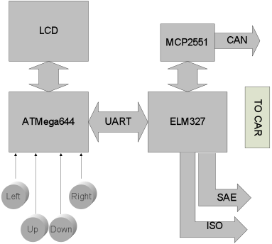
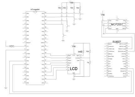
A high level drawing of how each different device was connected in our project is shown below. This shows how the MCU communicates with the various components needed to implement the OBD-II standard. The transmission arrows from the ELM327 for the SAE and ISO standard communications indicate transmission and receiving hardware for both, since they do not operate at 5V like the ELM327.
In regard to legal issues surrounding this project, we don't believe that we have breeched any legal boundaries in the creation or use of our project. Our LCD driver code falls under open source rules and the rest of the code is our own creation. If we were to attempt to produce this device commercially, we may be required to pay for our use of the SAE and ISO standards that we have implemented. Since we are not creating this device for commercial sale, our use of SAE and ISO standards information as provided by Wikipedia falls under fair use.
Hardware/Software Tradeoffs
One of the major design decisions in this lab was to use the ELM327 to communicate with the vehicle. It is certainly possible, and has been done before, to use a microcontroller to implement OBD-II communications with a specific brand of car. This is because although the OBD-II is a standard implemented in all cars sold in the US today, each car company has implemented it differently as described below, resulting in five distinct signaling protocols. Because of this, had we chose to implement all of the signaling and modulation in software, we would only have had time to implement one specific signaling protocol which would only work on certain types of cars. Because we wanted to be able to interface with many different types of cars, we chose to use the ELM327.
When deciding on a user interface we knew that we would require user input from buttons as was implemented in our final design. We also wanted to use an HD 44780 compliant LCD like the one's used in lab. Since we wanted to display more information and make it easily readable in a dark car, we chose a nice blue backlit 4 line HD 44780 compliant LCD found on Ebay.
Standards
There were by definition many standards we needed to abide by for our project to work correctly. The first, and most obvious, is the OBD-II standard. It has been required on cars sold in the US since 1996. One of the primary specifications of OBD-II is the connector: a 16-pin (2x8) SAE J1962 connector. A universal female side is provided on the car, usually under the steering wheel on the driver's side. It also specifies a standard set of diagnostic trouble codes (DTC's) that allow mechanics to identify problems with the vehicle, as when the "Check Engine" light comes on.
The signaling protocols are important to be aware of, even though we did not have to implement each one individually in our design. SAE J1850 defines the standard protocol used by most American car manufacturers. Ford Motor Company uses a variation on the J1850 protocol with pulsed width modulation and a +5V high voltage on the communication lines. General Motors uses a variation on the J1850 protocol with a variable pulsed width format and a +7V high voltage on the communication lines.
There are three ISO standard signaling protocols: ISO 9141-2, ISO 14230 KWP2000, and ISO 15765 CAN. ISO 9141-2 is very similar to RS-232 but it uses the battery voltage (12V) as a signal high voltage and is used primarily in Chryslers, European, and Asian vehicles. ISO 14230 KWP2000 is almost identical to ISO 9141-2 but with larger message lengths. Finally, the ISO 15765 CAN (Controller Area Network) protocol has been phased in as the only signaling protocol on cars sold the US, beginning in 2008.
Hardware Design
back to top
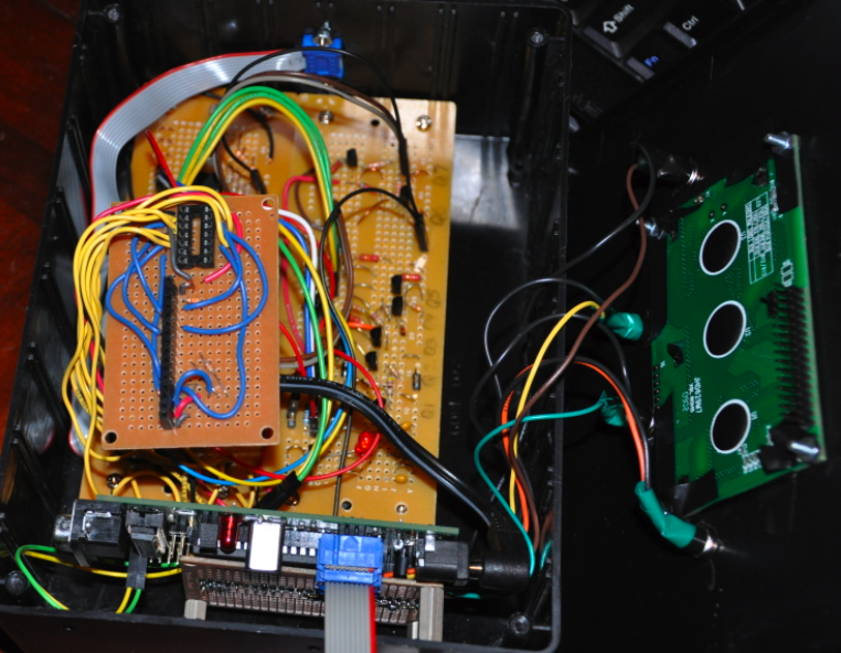
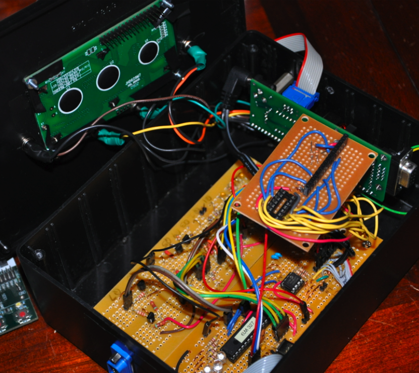
Because of the nature of this project there was a significant hardware component to the design. The major hardware components as shown above in the high level design are: the ELM327, the ISO/SAE/CAN transceiver hardware, the MCU and target board, the LCD screen, and the buttons. Early on we made the design decision that it would be most convenient to use this device if it were completely battery free, powered completely through the OBD-II port which draws 12V from the car's electrical system. This was consistent with the goal of our design, which was to make an easy to use OBD-II reader that is typically used in garages and not necessarily in close proximity to an outlet.
Voltage Regulation
To properly divide up the different hardware portions of this design requires an understanding of what each portion does and what kind of signals and voltages it will carry. The microcontroller target board is an all digital board with all voltages levels existing between 0 and 5V. The decision was made early on to leave the voltage regulator on this board and regulate the car's 12V to 5V on the target board using the on-board regulator provided (LMV340LAZ). The ELM327 is similar in function to the microcontroller in that it operates primarily in a digital 5V signals because it is a microcontroller itself. The MCP2551 CAN transceiver is also an all digital device. These two IC's along with indicator LEDs and a 4MHz crystal for the ELM327 were placed close together on one board that we referred to as the "digital board".
The analog board contained much of the transmission and receiving hardware necessary for implementing the SAE and ISO protocols, as well as voltage regulation. Unlike the 5V digital board, this "analog board" contains 12V, 5V, and 6V voltage levels on one board. A 78L05 12V-5V regulator provides the 5V source for the digital board as well as part of the SAE interface. The SAE interface also requires a 6V source, which is provided by a 317L regulator. The ISO interface operates at the battery voltage and so the 12V from the car is used to drive the transistors for ISO communication which is also found on this board. The 12V is not connected anywhere near the ELM327 on the digital board in an attempt to isolate it as much as possible from the 12V that can (and once during this project did) destroy the ELM327.
ELM327
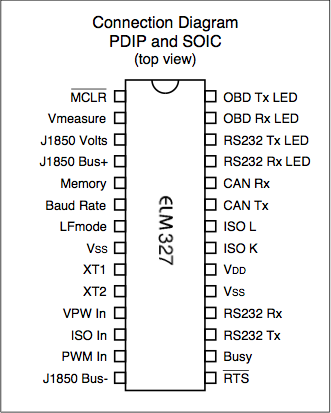
The ELM327 is really a specially programmed microcontroller PIC designed to handle communications in the OBD-II standard. It operates on the 5V rail provided on the digital board and provides debugging feedback via 4 LEDs that indicate Tx and Rx lines to the car and RS232 Tx and Rx. It operates at a frequency of 4MHz as provided by an attached crystal.
Data is received through one of the three signaling standards and then by the ELM327 which interprets the data and transmits it on a standard RS232 line that can be read by the ATMega644. Similarly, when a command is sent to the ELM327 by the MCU, it is interpreted and converted into the correct signaling protocol which is then transmitted to the car. The ELM327 does not actually read the commands or data that is being sent but simply converts ASCII data on the RS232 line to the proper voltages at the OBD-II port.
The transmission hardware is used to convert the signal output from the ELM327 into the proper voltages for the car. Since the SAE protocol requires 5V or 7V depending on whether it is using PWM mode or VPW, both of these voltages are fed using transistor pairs (PNP and NPN) to the actual transmission line that connects to the OBD-II port. The 7V (closer to 6.5V in practice) is provided from the 317L regulator.
The ISO transmission hardware is a relatively basic design that converts the 5V level from the ELM327 to the 12V battery voltage by tying the ELM327 pins to the base of 2 NPN transistors in a common emitter configuration. Similarly, the CAN protocol is implemented within the MCP2551 which is connected with two lines to the ELM327.
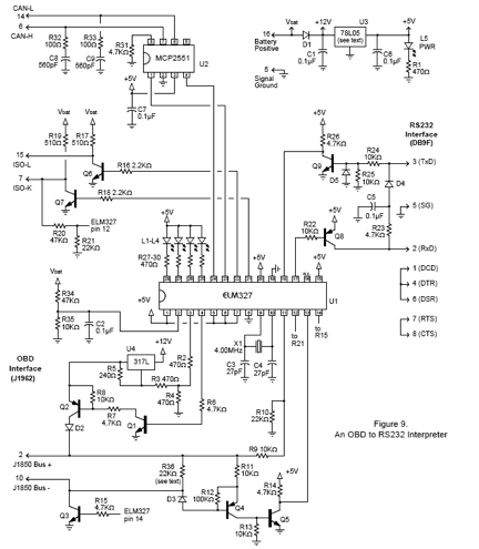
A detailed schematic of how the ELM327, MCP2551, and transceiver hardware were connected is shown in the appendix. On the schematic is an optional RS232 interface that we chose not to implement since it was not required to for communications with the MCU. The one major problem we encountered with this portion of the project was a blown ELM327 due to a 12V source reaching the digital board. Bruce and the TAs were able to assist us in locating the source of the high voltage (a poorly soldered resistor which was "popped" out with a little extra force) and the issue was corrected.
LCD
In order to re-use as much code as possible from existing LCD drivers, we chose to purchase an LCD screen with a Hitatchi HD44780 compliant driver onboard. This is the same LCD driver that is utilized in the LCD library provided by Bruce Land as part of this course, and we chose it due to our familiarity with it. Since we knew we wanted to have a relatively large menu structure with on-screen button labels, we chose a 4-line display because of the larger writing area it provided us. The LCD is wired to the target board through headers and the contrast is hardwired using a voltage divider to a setting that was found to be reasonable. The blue backlight to this screen was wired to 5V through a 330 ohm resistor which was found to be effective through experimentation.
Buttons
For user input we chose to use 4 basic push buttons that we found in lab. These buttons close a circuit internally when they are pressed and are spring loaded to open when not pressed. They are wired to ground on one side and to pins A0 through A3 on the other side. These pins are tied to 5V through 10 kilo-ohm resistors so that when the button is pressed, 0V is read at the microcontroller pin and only a small amount of current (0.5 mA) is drawn.
Target Board
In order to reduce the overall form factor of our device, we chose to construct a target board for the ATMega644. Not all of the ports are utilized, but the UART (pins D0 and D1) are the only ones used for communicating with the ELM. Port C is used for writing to the LCD and A0 through A3 are used for reading button press information. Everything but the UART lines is connected using a header board that simplified wiring during the development process. During the development process one of the problems we ran into was that the target board would sometimes fail to communicate properly with the ELM327. After much debugging and assistance from Bruce, the problem was found to be a loose power switch on the target board which was re-soldered and corrected.
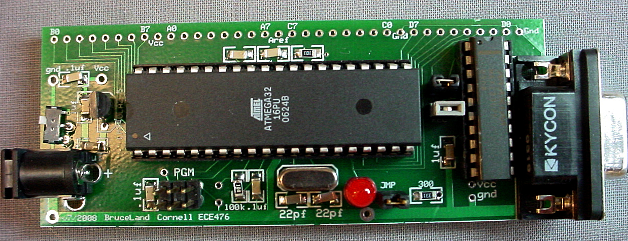
The target board was designed by Bruce Land for the ECE 4760 course.
Software Design
back to topThe software for the OBD2 reader makes use of a state machine to drive the UART communication based upon a given menu state. The software design begins with an upper level state machine, describing the interaction between the menu architecture and the UART communication. Following the chart are descriptions of the menu architecture and device functionality, UART communication, macros, and button dynamics.
Download the source code here: OBD2.c
Upper Level State Machine
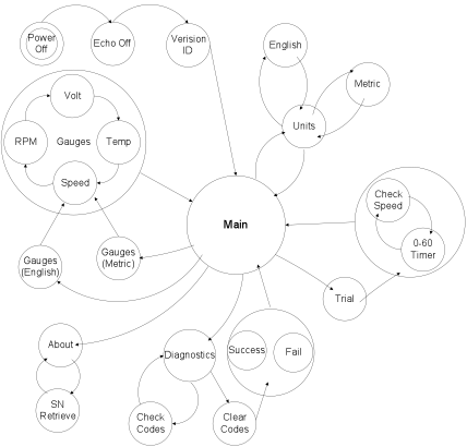
Power Up
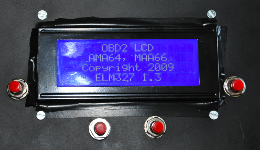
When the device is first powered, an initialization sequence takes place, as shown by the node 'power off'. The first command, echo off (refer to table for details on command), disables the ELM327 from echoing back the received characters to the host, the ATmega644. The power up splash screen shown below is completed after requesting the version identification from the ELM327. The screen is held for two seconds, and forwarded to the main menu.
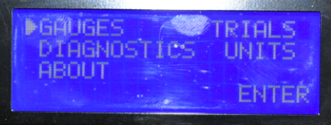
Main Menu
All roads lead to the main menu. This screen presents the user with five sections: gauges, diagnostics, about, trials, and units. An arrow is used as the indicator icon for menu navigation. When returning to the menu, the cursor is reset back to gauges. The user can scroll through the submenus by pressing either the up or down button, and confirming through a press of the right button. In order to insure the receive buffer is reset prior to entering another request state, the receive buffer index is set to zero upon returning to the main menu.
Gauges
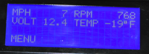
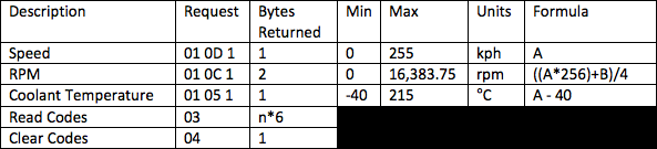
The gauges screen displays the speed, revolutions per minute, battery voltage, and engine coolant temperature in an easy to read layout. After printing the static text (all text besides numbers), the program enters a transmit/receive loop in order to update the measurements as fast as possible (refer to the ECU request table). If the user wishes to return to the main menu, pressing the left button will exit the gauges after the next receive.
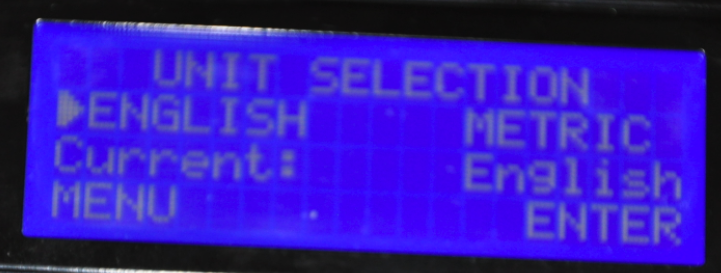
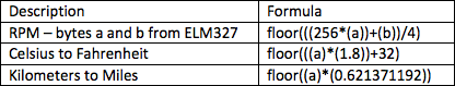
If this device were in use outside of the United States and the user wished to change the gauges from the English units to the Metric (SI) units, a visit to the units section on the main menu is all it takes. After choosing the appropriate units, returning to the gauges reflects the selection in the speed and coolant temperature. It is interesting to note that the ECU encodes this data in kilometers per hour and Celsius respectively, and macros, as defined in the table, are used in displaying this data under the English unit option.
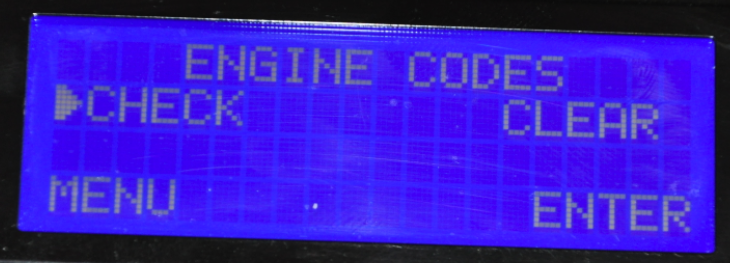
Diagnostics
Under the diagnostics submenu, the user has two options: check or clear the engine codes. The cursor is initially set to check the engine codes as it is assumed the user wishes to discover errors before clearing the notifications. A design decision was made to only accept the first three codes in the event that there are more than three engine codes flagged. The response length of an engine code request varies depending on the quantity of errors. Each line of data consists of six bytes, and a given error is described in two bytes. Excluding the first data line, three error codes are contained in an error packet. The raw hex values of the errors are displayed for the user, and can be referenced in an external lookup table. Further development would include an onboard lookup table containing error information.
After reviewing the errors present in the car, the user has the option of clearing all the stored trouble codes and turning off the check engine indicator lamp. SAE specifies that any commercial scan tool confirm that the request to clear is intentional, so a disclaimer screen was implemented. Upon confirmation, the clear code request is sent (refer to the table) and the response is judged for success or failure. Following success or failure, the program returns to the main menu.
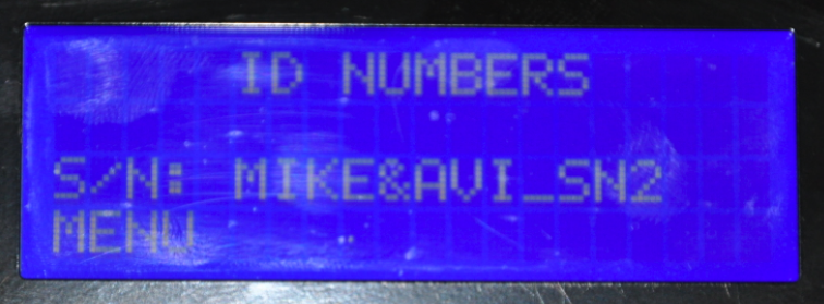
About
Each device manufactured is coded with a unique identifier as set by the developers. The purpose of this menu is to display the device serial number. After entering this submenu once, the MCU stores the serial number and does not request it if the about screen is entered again.
Trials
This submenu prepares the user for entering the zero to sixty miles per hour timing mode. Upon beginning the test, the MCU displays instructions for the user. If the vehicle is moving when the test begins, the driver is told to slow to zero. After the car has come to a complete stop, the driver is instructed to proceed when ready. As soon as the speed is read by the MCU as greater than zero, the timer begins. The test is completed by reaching sixty miles per hour or exceeding sixty seconds, at which point the speed and time are frozen. The user can return to the main menu after completing the test.
Unit Selection
This screen allows the user to select from the English and Metric (SI) unit system. The third line of the display indicates the current setting. Any changes in this submenu will be automatically reflected in the other menus.
UART Communication
The two microcontrollers, the ATmega644 and the ELM327, contain a standard UART type interface, and communicate over TX and RX pins. The ASCII character set is used in both requests and responses to the ELM327. It is important to note the difference in the end character of a message for both the transmission from the MCU and the response from the ELM327. When sending a request to the ELM327, a carriage return (hex value 0x0D) indicates the termination of a message; however, the ELM327 may respond with a multi-line message, using the carriage return character to simply end a line of data. Instead, the ELM327 uses a ">" prompt (hex value 0x3E) to notify the MCU it is in an idle state and ready to receive characters.
There are two different types of messages that can be sent to the ELM327. The first message type begins with "AT", as shown in the table below, and is used to read or modify data on the ELM itself. One of the luxuries associated with the ELM327 is that the message parsing is not case-sensitive. This means the commands "ATRV", "at rv", and "aT Rv", all read the voltage.
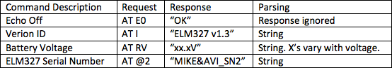
The second type of command, shown in the table below, is interpreted by the ELM327, reformatted into the appropriate protocol, and sent to the ECU on board the car. Such commands are comprised of a mode and a parameter id (PID). While the ELM327 is able to distinguish which messages are intended for ECU, it does not monitor the contents of the messages.
Wikipedia: OBD2 PID Codes
Macros
Before the program begins, there are macros defined to simplify the data conversion that occurs throughout the program, such as interpreting RPM, or changing from English to metric units.
Button Navigation
In addition to the hardware associated with button navigation, this device uses the lcd screen to indicate the meaning of the left and the right buttons. In certain menus, such as the main menu, the left button does not have a purpose, while in others it links back to the main menu. The purpose of the right button also changes given the menu. For example, in the gauges screen, the right button has no purpose while in the trials menu, it initiates the zero to sixty miles per hour test run.
Results of Design
back to topAccuracy and Timing
This device experiences timing variations as a result of differences in ECU response time. The OBD2 protocols are not subject to specific timing constraints. This limiting factor affects both the gauges and trial measurements. In the gauges screen, the speed, rpm, voltage, and coolant temperature are updated as fast as the ECU can respond. As soon as the previous response is received, the request for the next measurement is transmitted. Aside from the gauges, the zero to sixty miles per hour timer is dramatically affected. The timed trial is dependent upon the refresh rate of the speed measurement. The trial time is displayed after the speed measurement is successfully received. On average, the resolution of the timer in the trial is 0.3 seconds.
Safety Considerations
When building a device used in an automobile, safety is a major concern. For starters, it is very important to keep your eyes on the road. While the device displays useful information about the operation of the vehicle, it is in no way intended to distract the driver. The design proposal included a text to speech feature, which, due to time constraints, was not fully integrated. This would allow the driver to be aware of the information displayed on the screen, without causing a visual distraction.
In addition to the general use of the device, the specific abilities of the ELM327 need to be considered. As mentioned earlier, the ELM327 is able to manipulate protocols for data transmission but does not monitor the specific messages. Given the command to clear the engine codes, the ELM327 acts immediately, but the SAE specifies that scan tools verify the request is intentional. In order to meet these specifications, we included a disclaimer questioning the user if they repaired the engine prior to resetting the stored information.
While some manufacturers have custom codes available to modify the ECU data, there are no codes available to control the physical systems of the car. If the OBD2 reader were to fail and transmit random codes to the ECU, the physical systems would not malfunction. It is not possible for the device to steer the car, increase the speed, apply the breaks, or shut off/turn on the engine.
In testing this device, both Mike and Avi were sure to wear their seatbelts and abide the rules of the road, including speed limits, lane markers, and signaled, when appropriate. The device was read and operated by the passenger only, as to insure the safety of driver and passengers.
Interference/Usability
The OBD2 reader did not seem to have an impact on its surroundings. The device does not make use of any wireless systems, nor does it make annoying sounds that could distract other students in the laboratory.
The final construction of the device is extremely user friendly. The sleek look--black case with nothing but an lcd screen and buttons visible to users--presents a product. Avoiding the look of a couple of circuit boards wired together removes stress the user might experience in attaching such a device to their car. The screen colors, blue and white, do not discriminate for color-blind users; however, with the lack of text to speech, those who suffer from complete blindness cannot use our device. This is likely not an issue, as such users should not operate heavy machinery in the first place. It has been assumed that the user is literate, as reading is an essential aspect to this project. The coding practice was such to insure damage could not be done to the ECU. There is no combination of button presses the user could perform in order to cause the rewriting of on board parameters.
Ethical Considerations
As electrical engineers receiving instruction at such a prestigious institution as Cornell University, we must uphold the highest standards of research and development as set forth by the IEEE Code of Ethics. While we have agreed not to accept bribery with respect to rule number four, many different companies such as ELM electronics and Carplugs.com sponsored samples under the agreement that we would post a banner on our website. We believe this is not a form of bribery but a respectable form of bartering. After discussing the code of ethics while writing this report, we have fulfilled our duty in assisting each other in reinforcing the codes. Our communication throughout the project never created tension or conflict, nor was discrimination based on race, religion, gender, age, disability, or nationality an issue. All contributions of others, such as Bruce Land and Ruibing Wang, were properly documented. Honesty and positive criticism established a pleasurable working environment.
The development of this device is in no way intended for outside contractors. This reduces the limitation of proper training in the specific area of automobile electronic development. Through our research, we were able to make educated decisions in relation to automobile scan tool safety, as exemplified in our disclaimer for resetting the engine trouble codes.
Legal Considerations
Our device does not contain an RF transmitter so it does not fall under FCC regulations. As mentioned previously though, if it was to be sold commercially the proper approvals to implement SAE and ISO standards would need to be acquired. Additionally, legal considerations should be taken into account with product safety. We have done everything we can to make our product as safe as possible. If we had additional time we would have implemented text to speech capabilities to allow the driver to interact with the system without looking at the screen, but for now passengers may use the system during driving maneuvers. Finally, by implementing a confirmation screen for our clear code function, we comply with SAE requirements about how OBD-II readers clear diagnostic trouble codes.
Final Thoughts
Overall we found this project very fulfilling, although we ran into our fair share of roadblocks along the way. As Bruce had indicated at the beginning of this project, hardware was found to be a major source of problems during debugging and testing of our device. Broken resistors, poorly connected wires, and fried IC's hampered our efforts greatly since there was no way to test our software without properly functioning hardware.
We chose this project because we both enjoy cars and the idea of interfacing with the computers that have become so prevalent in our cars today was exciting for us. We are very glad we did choose this project because the hours of testing were much more enjoyable because we found the topic so interesting. It is also exciting field to be working with because there is so much room to expand on our idea
Appendix
back to topHardware Communications Schematic
ELM327 Hardware Schematic
Task Division
Develop Hardware Design/Layout - Mike
Build Hardware Elements and Enclosure - Mike
Develop and Implement Software Structure - Avi
Implement UART Communication Scheme - Avi
Developed and Implemented Menu Structure - Both
Performed Testing - Both
Wrote Report - Both
Datasheets
back to top
ELM327 Datasheet
MCP2551 Datasheet
OBD2LCD Project
Acknowledgements
We would like to acknowledge Bruce Land for providing us with the basis of knowledge from this course and for providing us with the LCD code for our LCD screen.
Additionally we would like to thank all the TAs who helped us during development. Finally, we would like to thank our sponsors listed above who allowed us to stay within budget despite a significant amount of hardware.
Sponsors
back to top