ECE 476 Final Project: LED Sensor Piano Keyboard
Cristina
Guzman (cgg27) and Joe Vulih (jpv23)
Contents
· Patents
· Accuracy
· Safety
· Intellectual property
considerations
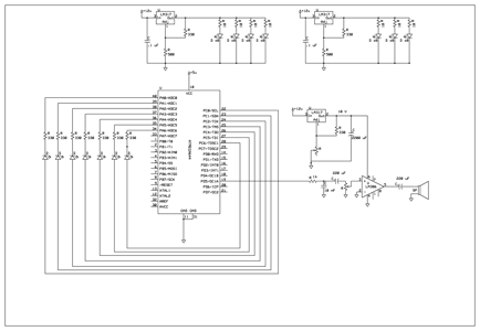
Appendix B: Overall
Schematics
Introduction
Our project utilizes an array of LEDs that work as light sensors to generate a musical tone, simulating a piano keyboard.
The basic idea is to use LEDs as both emitters and sensors. For our project specifically, we used a total of 63 LEDs, 9 for each of the seven natural keys. Only the middle LED served as photodetector when the key was pressed, absorbing light from the other LEDs reflected from the finger. We then used the Karplus-Strong algorithm for sound generation, all programmed in C. The tone was passed through an audio amplifier, and can be listened through headphones or speakers connected to the audio jack.
We chose this project because we wanted to do something with LEDs as
sensors, and specifically chose music because of our interest in this matter.
Back to top
High level design
· Patents
Rationale
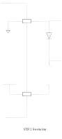
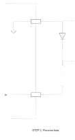
The rationale behind this idea consists of using a diode in a 3 step process, as shown in the following schematic. Each step is approximately 1 millisecond long. The upper pin will starts at Vcc and stay there for one millisecond (step one), and then drop to ground for two milliseconds (step two and three). The lower pin will start at ground for step 1, then rise to Vcc for the length of step two and finally the diode will discharge exponentially due to the hole-electron generation due to the incident light on the LED (8 pin leakages).

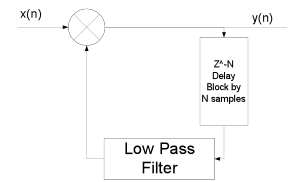
For the sound generation we will use the Karplus-Strong algorithm developed in the 80s, which is computationally simple. It is a method of physical modeling a string that simulates the sound of some types of instruments, including the piano. It uses a low pass filter and a delay block, which we will implement in software. A schematic of how it works is shown below.
Background Math
The output frequency for each note was calculated from the formula,

Where N is the length of the delay line, and fs is the sample frequency at which the loop is updated.
For this project we used a sample rate of 8 kHz. While this sample rate causes some quantization of possible frequencies since the delay line has only integer lengths, we were still able to get relatively accurate frequency synthesis.
The input x(n) is excited using a signal noise until the delay line is filled to excite the entire system.
The low pass filter is simply a moving average, which has the equation below
![]()
where g is a loss factor that must be
less than 0.5 for the system to be stable. By making g smaller the signal will
die out faster.
Logical structure
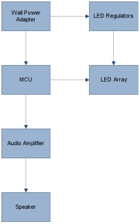
Above is a block diagram of the system wiring. The MCU interfaces with the LED array to get the human touch interfaces, and then produces a sound output that is passed through the audio amplifier to the speakers.
Hardware/Software Tradeoffs
We implemented a low pass filter in software for the Karplus-Strong algorithm. Even though low pass filters can be made with hardware, for this part it was necessary to do it in software.
Also, while we implemented the Karplus-Strong in software, the algorithm would work much faster in hardware, but we did not have the expertise nor the time to design on the algorithm on an FPGA.
We also decided to
use integers for our variables in our code instead of floats because even though
this gives less accuracy, it is faster and timing was more of an issue.
Standards
One standard that we followed in our design is ISO 16:1975
that specifies that in music the A above middle C is 440 Hz.
Patents
Some
intellectual property rights we considered are two patents, both concerning the
Karplus-Strong algorithm. One patent is the “Wavetable-modification
instrument and method for generating musical sound” (Patent Number 4,649,783) and the other is
“Independently controlled wavetable-modification instrument and method for
generating musical sound” (4,622,877).
They are both expired, since they were filed in the early 80s.
Program design
The software was grouped into two functions. The first was the sensing of the LEDs and the second was the generation of the audio tones.
The LED sensing was controlled by a state machine that updated approximately every millisecond and scanned the entire keypad one button at a time. Since we only had 7 buttons, we were able to scan the keypad in around 16 ms. This routine would then either reinitialize the Karplus-Strong routine for a specific button, or it would change the damping on the string to shut off a button.
The Karplus-Strong sound synthesis was always running. The strings were always being updated, and whether they were playing audibly or not was depended on the damping on the string. The button routine would set the damping really high if the button was not pressed. This is equivalent to the strings of the piano always being present, except being heavily damped.
A part that was tricky to write the part of summing of each of the outputs from the Karplus-Strong. This was difficult due to the fact that we were using only a 10 bit PWM on timer 1. To do this we first added up all the outputs as longs, then, since they are represented using 16 bits, we right shifted the value by 9 bits since the addition of 7 16 bit numbers could produce 19 bits of output. Then an offset was added to center the PWM at the middle of its range.
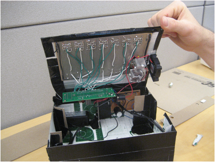
Hardware design
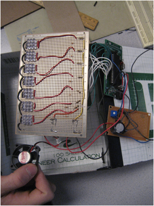
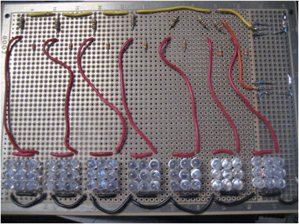
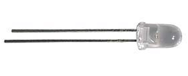
The major hardware components were the 63 Ultra Red 1000mcd 5mm LEDs. These 1-inch LEDs have a water clear epoxy. The maximum forward current is 20mA, with a maximum forward drop of 2.0 V and maximum reverse voltage of 5 V. All these were soldered to the large bread board, by arranging them by 9 LEDs (3 rows, 3 columns) per key. To limit the current through the LEDs a 10 ohm resistor was used for the 8 non sensor LEDs in each key, and a 330 ohm resistor was used for the sensor LED. The rims of the LEDs were trimmed using the Dremel tool to remove the flange to get the LEDs to fit closer together.
One thing that we tried and did not work was to use the oscilloscope
while testing. This was because the scope loaded the LEDs too much and
corrupted their discharge time, so the device would not operate properly.
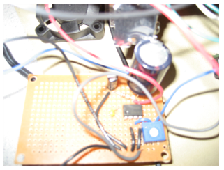
Two LM317TFS
Voltage Regulators were used, which
are capable of supplying 1.5 A of
current, with an adjustable output voltage from 1.2V to 37V. They were configured to output approximately 3.2 V for the
LEDs.
One regulator was used for 4 keys, while the other was used for the other 3. A small piece of aluminum sheeting was used to make a heat sink for each of them, and a fan was used to keep these regulators cool, as seen in the picture below.
For the output we used an LM386 audio power amplifier with a
variable gain from 20 to 200. Set up
the device to use a gain of 20 to prevent saturating the output. It came in an 8
pin DIP package, which can be seen in the picture below.
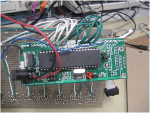
The Atmel ATMega
664 was used to control the
entire system. This was mounted on a board that includes a power supply, crystal clock, and
programming interface. A six-pin header allows flash memory programming from an
STK500 or other Atmel programmer.
Results of the design
· Accuracy
· Safety
Speed of Execution
Timer 0, controlled of the polling of the LEDs, was ran at a speed of approximately 1millisecond. This updated the state machine, which had 16 total states. This meant that we could scan the entire LED array is approximately 16 ms. The actual polling of the LEDs was put in another routine so that it could be interrupted by the much faster Timer 1 ISR.
Timer 1 was executed at a speed of 8kHz to control the sampling of the Karplus-Strong algorithm.
Timer 2 was clocked at 20 MHz to generate the PWM output for the audio signal on pin D5.
Accuracy
The frequencies for the 7 naturals used in our keyboard are:
|
Note |
Frequency (Hz) |
Wavelength (cm) |
|
C4 |
261.63 |
132 |
|
D4 |
293.66 |
117 |
|
E4 |
329.63 |
105 |
|
F4 |
349.23 |
98.8 |
|
G4 |
392.00 |
88.0 |
|
A4 |
440.00 |
78.4 |
|
B4 |
493.88 |
69.9 |
Safety
There are no safety considerations with our project since we
are not using extremely bright LEDs (which could affect the retina) nor will
the volume be too high to affect the human ear. However, as with any light
source, like a bulb, staring at it for a prolonged period of time could damage
the eyes.
Interference
Our project does not radiate any harmful signals that would interfere with any electric circuits to our knowledge. And our project accepts all interference.
Usability
Our product will be used as recreation for people interested in music and playing the piano. People with special needs will not be using our product, with the exception of the blind. They could play the notes but will not be able to appreciate the LEDs. The behavior of the LED buttons varies based on skin reflectivity; however, we have calibrated the sensitivity to respond to the lowest reflectivity. However, this means the interface will behave differently with skin tones.
Conclusions
· Intellectual property
considerations
Expectations
In conclusion, our final project met all the specs that we initially set out to do. We used LEDs as sensors to simulate a piano octave. We used the Karplus-Strong algorithm to accurately generate sound. We stayed well below the $75 dollar limit, and even spent less than we predicted.
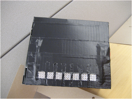
While we are happy with out results, there are some things
that could be improved. First of all,
we could increase the accuracy of the PWM from 12 bit to 16 bit. We could also
add the flat/sharp tones to the octave, as a piano has. Finally we could use a
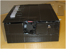
plastic enclosure instead of a cardboard one.
Applicable standards
The only standard we had to follow has that A440 is the standard for
musical pitch, the ISO 16:1975. As it is seen in the accuracy results
section, we did follow this standard for all notes in our octave, beginning
with middle C.
Intellectual property considerations
There were no intellectual property considerations since we did not reuse someone’s code or design. We did not use code from the public domain either. Or reverse engineering. Although we used the Karplus-Strong algorithm, this patent expired so there were no issues.
We also did not sample any parts that required non-disclosure forms to
be signed.
There are no current patent or publishing opportunities for this
project.
Ethical considerations
Since we are committed to the highest ethical and
professional conduct, we abided by the IEEE Code of Ethics when developing this
project. We were consistent specifically with rules 7, 8 and 10. Rule 7 states
that we agree “to seek, accept, and offer honest criticism of technical work,
to acknowledge and correct errors, and to credit properly the contributions of
others”. We credited the Karplus-Strong Algorithm for sound generation, as well
as sought and accepted help from our professor Bruce Land and other teaching
assistants. We also credit our several sources that gave us information about
using LEDs as sensors.
Rule 8 states “to treat fairly all persons regardless of
such factors as race, religion, gender, disability, age, or national origin”.
We took this into consideration when setting our detection threshold, since
different skin tones respond in distinct ways. Our LED piano senses even the
least reflective skin tones, so there is no discrimination towards race. Also
any person, from any country, of any age and gender can use our project. As we
stated before, people with disabilities will not be
using our product, with the exception of the blind.
Rule 10 affirms that we are to “to assist colleagues and co-workers in their professional development and to support them in following this code of ethics”. There is another group that is also producing musical strings for their project, and when they asked for help we supported them by giving them advice on what we had done. We also offered advice to other groups working with LED and getting them to fit on the bread boards which had pin spacings that were rather small.
Legal considerations
There are no legal considerations, since all
patents have expired.
Appendix A: Commented Code
#include
<inttypes.h>
#include
<avr/io.h>
#include
<avr/interrupt.h>
#include
<avr/sleep.h>
#include
<util/delay.h>
#include
<math.h>
#include
<stdlib.h>
//timeout
values for each task
#define
t1 1 // 19 for timer 1 ovf
#define
adcThresh 25
#define
begin {
#define
end }
#define
g_on 0.49999
#define
g_off 0.001
//===
fixed conversion macros =========================================
#define
int2fix(a)
(((int)(a))<<8) //Convert char to
fix. a is a char
#define
fix2int(a)
((uint8_t)((a)>>8)) //Convert fix to int. a is an int
#define
float2fix(a) ((int)((a)*256.0)) //Convert float to
fix. a is a float
#define
fix2float(a) (((float)(a))/256.0) //Convert fix to float. a is
an int
//
identify the assembler routine to C
extern
int multfix(int a,int b);
void
pollLED(void);
void
initialize(void); //all the usual mcu stuff
volatile
unsigned char time1 ; //timeout
counters
//Global
Variables
unsigned
char var;
unsigned
char readLED;
unsigned
char keyNum;
signed
int init_str[100];
volatile
signed int g_off_fix;
volatile
signed int g_on_fix;
//
C4 Variables
volatile
signed int APF_C4;
volatile
signed int LPF_C4;
volatile
int N_C4=59;
volatile
signed int delay_C4[60];
volatile
char out_C4;
volatile
char last_C4;
volatile
char play_C4;
volatile
int C4_ocr;
volatile
signed int g_C4;
//
D4 Variables
volatile
signed int APF_D4;
volatile
signed int LPF_D4;
volatile
int N_D4=53;
volatile
signed int delay_D4[54];
volatile
char out_D4;
volatile
char last_D4;
volatile
char play_D4;
volatile
int D4_ocr;
volatile
signed int g_D4;
//
E4 Variables
volatile
signed int APF_E4;
volatile
signed int LPF_E4;
volatile
int N_E4=47;
volatile
signed int delay_E4[48];
volatile
char out_E4;
volatile
char last_E4;
volatile
char play_E4;
volatile
int E4_ocr;
volatile
signed int g_E4;
//
F4 Variables
volatile
signed int APF_F4;
volatile
signed int LPF_F4;
volatile
int N_F4=44;
volatile
signed int delay_F4[45];
volatile
char out_F4;
volatile
char last_F4;
volatile
char play_F4;
volatile
int F4_ocr;
volatile
signed int g_F4;
//
G4 Variables
volatile
signed int APF_G4;
volatile
signed int LPF_G4;
volatile
int N_G4=39;
volatile
signed int delay_G4[40];
volatile
char out_G4;
volatile
char last_G4;
volatile
char play_G4;
volatile
int G4_ocr;
volatile
signed int g_G4;
//
A440 Variables
volatile
signed int APF_A440;
volatile
signed int LPF_A440;
volatile
int N_A440=35;
volatile
signed int delay_A440[36];
volatile
char out_A440;
volatile
char last_A440;
volatile
char play_A440;
volatile
int A4_ocr;
volatile
signed int g_A4;
//
B4 Variables
volatile
signed int APF_B4;
volatile
signed int LPF_B4;
volatile
int N_B4=31;
volatile
signed int delay_B4[32];
volatile
char out_B4;
volatile
char last_B4;
volatile
char play_B4;
volatile
int B4_ocr;
volatile
signed int g_B4;
volatile
signed int temp;
char
forward;
//**********************************************************
//timer
2 compare ISR which controls the timing of the LEDs
ISR
(TIMER2_COMPA_vect)
begin
--time1;
end
//
Audio Output ISR
ISR
(TIMER0_COMPA_vect) {
//PORTB=PORTB ^
0x08;
if(play_C4 == 1)
{
// update
output OCR
C4_ocr
= (delay_C4[out_C4]);
delay_C4[last_C4]=
multfix(g_C4,delay_C4[last_C4]+C4_ocr);
// Check for
pointer wrap around
if(out_C4==(N_C4)){
out_C4=0;
}else
{
out_C4++;
}
if(last_C4==(N_C4)){
last_C4=0;
}else
{
last_C4++;
}
}
if(play_D4 == 1)
{
D4_ocr
= (delay_D4[out_D4]);
delay_D4[last_D4]=
multfix(g_D4,delay_D4[last_D4]+D4_ocr);
if(out_D4==(N_D4)){
out_D4=0;
}else
{
out_D4++;
}
if(last_D4==(N_D4)){
last_D4=0;
}else
{
last_D4++;
}
}
if(play_E4 == 1)
{
E4_ocr
= (delay_E4[out_E4]);
delay_E4[last_E4]=
multfix(g_E4,delay_E4[last_E4]+E4_ocr);
if(out_E4==(N_E4)){
out_E4=0;
}else
{
out_E4++;
}
if(last_E4==(N_E4)){
last_E4=0;
}else
{
last_E4++;
}
}
if(play_F4 == 1)
{
F4_ocr
= (delay_F4[out_F4]);
delay_F4[last_F4]=
multfix(g_F4,delay_F4[last_F4]+F4_ocr);
if(out_F4==(N_F4)){
out_F4=0;
}else
{
out_F4++;
}
if(last_F4==(N_F4)){
last_F4=0;
}else
{
last_F4++;
}
}
if(play_G4 == 1)
{
G4_ocr
= (delay_G4[out_G4]);
delay_G4[last_G4]=
multfix(g_G4,delay_G4[last_G4]+G4_ocr);
if(out_G4==(N_G4)){
out_G4=0;
}else
{
out_G4++;
}
if(last_G4==(N_G4)){
last_G4=0;
}else
{
last_G4++;
}
}
if(play_A440 ==
1) {
A4_ocr=(delay_A440[out_A440]);
delay_A440[last_A440]=
multfix(g_A4,delay_A440[last_A440]+A4_ocr);
if(out_A440==(N_A440)){
out_A440=0;
}else
{
out_A440++;
}
if(last_A440==(N_A440)){
last_A440=0;
}else
{
last_A440++;
}
}
if(play_B4 == 1)
{
B4_ocr
= (delay_B4[out_B4]);
delay_B4[last_B4]=
multfix(g_B4,delay_B4[last_B4]+B4_ocr);
if(out_B4==(N_B4)){
out_B4=0;
}else
{
out_B4++;
}
if(last_B4==(N_B4)){
last_B4=0;
}else {
last_B4++;
}
}
//Sum the OCR variables of all
the keys, and perform a right shift to prevent overflow, then add an offset
OCR1A =
((((long)C4_ocr + (long)D4_ocr + (long)E4_ocr + (long)F4_ocr + (long)G4_ocr +
(long)A4_ocr + (long)B4_ocr))>>9) + 512;
}
//**********************************************************
//Entry
point and task scheduler loop
int
main(void)
begin
initialize();
DDRC = 0xff;
PORTC=0xff;
//main task scheduler loop
while(1)
begin
//
reset time and call task
if (time1==0){ time1=t1;
pollLED();}
end
end
//*******************************
//Polls
the LED sensors to see if the current one being read is on
//and
provides visual output recognition
void
pollLED(void) {
if (var==0){
//forward
bias all
DDRA
= 0xff;
PORTA
= 0x00;
PORTC
= 0xff;
var
= 1;
} else if
(var==1) {
//reverse
bias key 1, forward bias the rest
DDRA = 0b11111111;
PORTA
= 0b00000001;
PORTC
= 0b11111110;
var=2;
} else if
(var==2) {
//
Key 2, PinA high output, Pin C low output
//
Key 1, PinA low input, Pin C low output
//
forward bias the rest
DDRA = 0b11111110;
PORTA
= 0b00000010;
PORTC
= 0b11111100;
//
Set mux to key 1
ADMUX
= (1<<ADLAR) | (1<<REFS1) | (1<<REFS0);
var=3;
} else if
(var==3) {
//
Poll ADC value
ADCSRA
= ((1<<ADEN) | (1<<ADSC) | (1<<ADSC)) + 7;
var
= 4;
} else if
(var==4) {
//
ADC value has finished converting, determine press
readLED
= ADCH;
// Determine if
the key was pressed
if(readLED
<= adcThresh) {
//
If so, was it pressed the last time it was polled
if(g_C4 == g_off_fix) {
// if not, then load the delay line and set the damping to that of a
pressed key
play_C4
= 0;
for(int
i=0; i<=N_C4;i++){
delay_C4[i]=
init_str[i];
}
g_C4
= g_on_fix;
play_C4
= 1;
}
}
else {
// Other wise set the damping to an off key
g_C4
= g_off_fix;
}
//Key
3, Pin A high output, Pin C low output
//Key
2, Pin A low input, PinC low output
DDRA = 0b11111101;
PORTA
= 0b00000100;
PORTC
= 0b11111001;
//
Set mux to key 1
ADMUX
= ((1<<ADLAR) | (1<<REFS1) | (1<<REFS0)) + 1;
var=5;
} else if
(var==5) {
ADCSRA
= ((1<<ADEN) | (1<<ADSC) | (1<<ADSC)) + 7;
var
= 6;
} else if
(var==6) {
//
ADC value has finished converting, determine press
readLED
= ADCH;
if(readLED
<= adcThresh) {
if(g_D4
== g_off_fix) {
play_D4
= 0;
for(int
i=0; i<=N_D4;i++){
delay_D4[i]=
init_str[i];
}
g_D4
= g_on_fix;
play_D4
= 1;
}
}
else {
g_D4
= g_off_fix;
}
//Key
4, Pin A high output, Pin C low output
//Key
3, Pin A low input, PinC low output
DDRA = 0b11111011;
PORTA
= 0b00001000;
PORTC
= 0b11110011;
//
Set mux to key 1
ADMUX
= ((1<<ADLAR) | (1<<REFS1) | (1<<REFS0)) + 2;
var=7;
} else if
(var==7) {
ADCSRA
= ((1<<ADEN) | (1<<ADSC) | (1<<ADSC)) + 7;
var
= 8;
} else if
(var==8) {
//
ADC value has finished converting, determine press
readLED
= ADCH;
if(readLED
<= adcThresh) {
if(g_E4
== g_off_fix) {
play_E4
= 0;
for(int
i=0; i<=N_E4;i++){
delay_E4[i]=
init_str[i];
}
g_E4
= g_on_fix;
play_E4
= 1;
}
}
else {
g_E4
= g_off_fix;
}
//Key
5, Pin A high output, Pin C low output
//Key
4, Pin A low input, PinC low output
DDRA = 0b11110111;
PORTA
= 0b00010000;
PORTC
= 0b11100111;
//
Set mux to key 1
ADMUX
= ((1<<ADLAR) | (1<<REFS1) | (1<<REFS0)) + 3;
var=9;
} else if
(var==9) {
ADCSRA
= ((1<<ADEN) | (1<<ADSC) | (1<<ADSC)) + 7;
var
= 10;
} else if
(var==10) {
//
ADC value has finished converting, determine press
readLED
= ADCH;
if(readLED
<= adcThresh) {
if(g_F4
== g_off_fix) {
play_F4
= 0;
for(int
i=0; i<=N_F4;i++){
delay_F4[i]=
init_str[i];
}
g_F4
= g_on_fix;
play_F4
= 1;
}
}
else {
g_F4
= g_off_fix;
}
//Key
6, Pin A high output, Pin C low output
//Key
5, Pin A low input, PinC low output
DDRA = 0b11101111;
PORTA =
0b00100000;
PORTC
= 0b11001111;
//
Set mux to key 1
ADMUX
= ((1<<ADLAR) | (1<<REFS1) | (1<<REFS0)) + 4;
var=11;
} else if
(var==11) {
ADCSRA
= ((1<<ADEN) | (1<<ADSC) | (1<<ADSC)) + 7;
var
= 12;
} else if
(var==12) {
//
ADC value has finished converting, determine press
readLED
= ADCH;
if(readLED
<= adcThresh) {
if(g_G4
== g_off_fix) {
play_G4
= 0;
for(int
i=0; i<=N_G4;i++){
delay_G4[i]=
init_str[i];
}
g_G4
= g_on_fix;
play_G4
= 1;
}
}
else {
g_G4
= g_off_fix;
}
//Key
7, Pin A high output, Pin C low output
//Key
6, Pin A low input, PinC low output
DDRA = 0b11011111;
PORTA
= 0b01000000;
PORTC
= 0b10011111;
//
Set mux to key 1
ADMUX
= ((1<<ADLAR) | (1<<REFS1) | (1<<REFS0)) + 5;
var=13;
} else if
(var==13) {
ADCSRA
= ((1<<ADEN) | (1<<ADSC) | (1<<ADSC)) + 7;
var
= 14;
} else if
(var==14) {
//
ADC value has finished converting, determine press
readLED
= ADCH;
if(readLED
<= adcThresh) {
if(g_A4
== g_off_fix) {
play_A440
= 0;
for(int
i=0; i<=N_A440;i++){
delay_A440[i]=
init_str[i];
}
g_A4
= g_on_fix;
play_A440
= 1;
}
}
else {
g_A4
= g_off_fix;
}
//Key
7, Pin A low input, PinC low output
DDRA = 0b10111111;
PORTA
= 0b00000000;
PORTC
= 0b10111111;
//
Set mux to key 1
ADMUX
= ((1<<ADLAR) | (1<<REFS1) | (1<<REFS0)) + 6;
var=15;
} else if
(var==15) {
ADCSRA
= ((1<<ADEN) | (1<<ADSC) | (1<<ADSC)) + 7;
var
= 16;
} else if
(var==16) {
//
ADC value has finished converting, determine press
readLED
= ADCH;
if(readLED
<= adcThresh) {
if(g_B4
== g_off_fix) {
play_B4
= 0;
for(int
i=0; i<=N_B4;i++){
delay_B4[i]=
init_str[i];
}
g_B4
= g_on_fix;
play_B4
= 1;
}
}
else {
g_B4
= g_off_fix;
}
//Key
5, Pin A high output, Pin C low output
//Key
4, Pin A low input, PinC low output
DDRA = 0b11111111;
PORTA
= 0b00000000;
PORTC
= 0b11111111;
//
Set mux to key 1
ADMUX
= ((1<<ADLAR) | (1<<REFS1) | (1<<REFS0)) + 7;
var=1;
}
}
//**********************************************************
//Set
it all up
void
initialize(void) {
//set up the ports
// PORT A is used as the CATHODE
(ground) of the sensing LEDs,
// which will be charged and
floated each time the LED is polled
DDRA=0x0f; // PORT A is an output
PORTA=0;
// PORT C is used as the ANODE
(vdd) of the LEDs
DDRC = 0xff;
//init the task timers
time1=t1;
//set variable for key poll sweep
keyNum = 0;
//init the A to D converter
//channel zero/ left adj
/INTERNAL Aref
//!!!DO NOT CONNECT Aref
jumper!!!!
ADMUX = (1<<ADLAR) |
(1<<REFS1) | (1<<REFS0);
//enable ADC and set prescaler to
1/128*20MHz=156,250
//and clear interupt enable
//and start a conversion
ADCSRA = ((1<<ADEN) |
(1<<ADSC)) + 7;
// The initial condition on the
delay lines preloaded into an array
for(int i=0; i<100;i++){
init_str[i]
= rand();
}
// Initiallize all the playback
variables
g_off_fix = float2fix(g_off);
g_on_fix = float2fix(g_on);
g_C4=g_off_fix;
g_D4=g_off_fix;
g_E4=g_off_fix;
g_F4=g_off_fix;
g_G4=g_off_fix;
g_A4=g_off_fix;
g_B4=g_off_fix;
out_C4=1;
last_C4=0;
out_D4=1;
last_D4=0;
out_E4=1;
last_E4=0;
out_F4=1;
last_F4=0;
out_G4=1;
last_G4=0;
out_A440=1;
last_A440=0;
out_B4=1;
last_B4=0;
// Audio output
DDRD = 0xff;
// Timer 2 for Polling LEDs
TIMSK2 = (1 << OCIE2A); // Timer 2 Interrupt Enable
OCR2A = 200;
TCCR2B = 5; //
divide by 128 prescalar
TCCR2A= (1<<WGM21); //
Turn on clear on compare match
/* Timer 0 for update rate*/
// timer 0 runs at full rate
TCCR0B = 3;
//turn on timer 0 overflow ISR
TIMSK0 = 2 ;
TCCR0A = (1<<WGM01) ; //
divide by 64
OCR0A = 39;
/* Timer 1 for 10 bit PWM
operation */
// No Prescaling, Fast PWM 10 Bit
TCCR1B = (1<<WGM12) |
(1<<CS10);
// Fast PWM 10 bit
TCCR1A = (1<<COM1A1) |
(1<<COM1A0) | (1<<WGM11) |(1<<WGM10);
//crank up the ISRs
sei();
}
;******************************************************************************
;*
;*
FUNCTION
;* muls16x16
;*
DECRIPTION
;* Signed multiply of two 16bits
numbers with 16 bits result.
;*
USAGE
;* r25:r24 = r23:r22 * r25:r24
;******************************************************************************
;int
multfix(int a,int b)
.global
multfix
multfix:
;input parameters
are in r23:r22(hi:lo) and r25:r24
;b
aready in right place -- 2nd parameter is in r22:23
mov
r20,r24 ;load a -- first parameter is in r24:25
mov r21,r25
muls r23, r21 ; (signed)ah *
(signed)bh
mov r25, r0 ;r18, r0"
mul r22, r20 ; al * bl"
mov r24, r1 ;movw r17:r16, r1:r0"
mulsu r23, r20 ; (signed)ah * bl
add r24, r0 ;r17, r0"
adc r25, r1 ;r18, r1"
mulsu r21, r22 ; (signed)bh * al
add r24, r0 ;r17, r0"
adc r25, r1 ;r18, r1"
clr r1 ;
required by GCC
;return values
are in 25:r24 (hi:lo)
Ret
Back to top
Appendix B: schematics
Appendix C: cost details
|
Part |
Quantity |
Price |
|
LEDs |
100 |
$14 |
|
Resistors (309 ohms) |
7 |
Free |
|
Resistors (10 Kohms) |
7 |
Free |
|
Large bread board |
1 |
Free (Surplus) |
|
Small bread board |
1 |
$1 |
|
ATMega664 |
1 |
$8 |
|
Fan |
1 |
$1 |
|
Regulators (LM317TFS) |
2 |
Free (Surplus) |
|
Protoboard |
1 |
$4 |
|
Audio Amplifier (LM386) |
1 |
Free (Surplus) |
|
|
Total |
$ 28 |
Appendix D: Tasks
Here is a list of the specific
tasks in the project carried out by each team member.
Writing the Code: Joe
Testing the Code: Both
Ordering and buying parts for the
project: Joe
Designing the Hardware: Joe
Testing the Hardware: Both
Soldering the Parts: Both
Integration and final testing:
Both
Writing the Report: Both
Creating the webpage: Cristina
Appendix E: References
1. Data sheets
2. Vendor sites
3. Background sites/papers
Gordon McLellan's Blog, justDIY
Julius O. Smith III's Digital Waveguide Synthesis Page