Black Out
Chris McNally (csm44) and Hung Dang (hvd2)
1
Introduction
Black Out is an electronic puzzle game that is a derivative of Lights Out released by Tiger Toys in 1995 but with a few additional twists.
The game consists of a 4 by 4 grid of LEDs with each LED having a total of four states (off, red, blue and green). Sixteen electrode pads coupled with two capacitive touch sensors are used to give gamers full interaction with the game. In addition, the game includes a special playback feature which gives gamers hints to solving the puzzle.
Black Out is a project that was implemented as a final project for ECE 476 design lab. It took five weeks to design and build. The result is a working game that is both fun and challenging to play. Please refer to our results section for pictures of the completed game.
2
High
Level Design
2.1 Rationale
Originally we envisioned a project that is along the line of a small led dance floor. Our first inspiration was from MIT's 128 square foot disco dance floor. We wanted to instead build a 4 by 4 led dance floor complete with touch sensors covering an area of 16 square feet. However, after consulting with Bruce and a few TAs and researching the cost of materials needed to build the frame for such dance floor, we came to a conclusion that the project was too expensive to implement. We settled on the idea of doing a proof-of- concept by building a scaled down version of the 16 square foot led dance floor.
Thus our project was born, a small table top disco dance floor, for which one can use fingers to dance instead. This dance floor would have touch sensors and LEDs that change color in a specific manner corresponding to touches. One of the first major decisions we had to make was the number of LEDs or the size of the table top dance floor. Atmega64 board has a limited number of ports. We wanted to use tri-color LEDs to enhance the presentation, which tripled the amount of ports we needed. Furthermore, we also had to put into consideration the time it takes and how hard it is to wire up the LEDs. A 4 by 4 grid consists of 16 tri-color LEDs was a reasonable number in both practicality and cost.
For touch sensing, we took up Bruce's suggestion of using capacitive touch sensors. Again our project took an expected turn. We used aluminum foils as electrodes and couldn't find a good way to integrate the touch sensors and LEDs together. For a good presentation, our design needed the LEDs to be underneath an opaque material preferably glass but having an opaque layer would then prevent the electrodes from sensing touches. We finally decided to simplify our project by keeping the LEDs and capacitive touch sensors separate. The LEDs are grouped together into a 4 by 4 grid which are then controlled by transistors. The electrodes are grouped and tied to a piece of cardboard and are hooked up to two capacitive touch sensors. Both modules are controlled by an Atmega64 board.
The decision to keep both portions separate forced us to abandon the led dance table top project idea. Our main objective became to implement an interactive led display using capacitive touch sensors as inputs. This is when we finally came up with the game idea of Lights Out. It is a simple project idea that we instantly felt appropriate since it struck a balance between software and hardware.
2.2
Background
Math
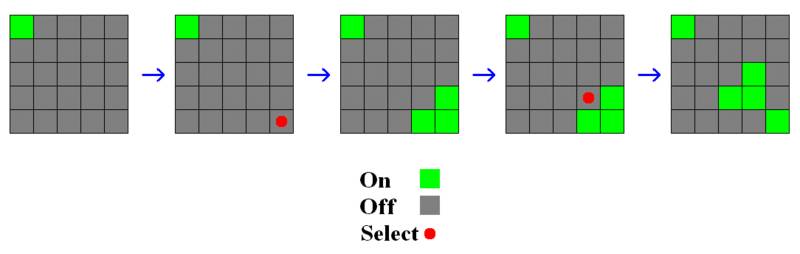
The only background math this project required was some of the mathematical foundations of Lights Out. When a square was toggled, that square and all squares surrounding it changed state. For the original lights out game, each button had two possible states (on and off). Our version will have 4 states (off, red,green,blue). Generating solutions for a given board set up can be done by representing the board as a matrix and each LED assigned a value in the matrix.
A randomly generated board is not guaranteed to be solvable. The solvability of any given board can be determined by looking for certain patterns in the layout, most easily done by again using linear algebra and matrices.
2.3
Logical
Structure
The project consisted of two main portions: touch sensing and LED control. Touch sensing was done using two Freescale MC33794 capacitive touch sensors. Each sensor was connected to 9 electrodes, 8 LED switches and 2 command buttons. The capacitive touch sensors outputted a voltage inversely related to measured capacitance on the selected channel. This voltage was read using the built in ADC on the Mega644 and used to determine when an electrode was touched by the user.
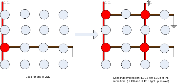
The second part of the project consisted of controlling the LEDs. Each LED had three cathode connections for each color, and a common anode for all three colors in the housing. To control which color was turned on, we connected all the common anode’s in a column to a switch, and then connected all the cathodes of one color in a row to another switch to ground. This allowed us to address a specific LED color and turn it on by simply connecting a column to power and grounding a row. This scheme worked well for turning on one LED at a time, but when multiple LEDs are lit up in different columns or rows, the system does not work as well. The problem arises because the entire column and row are connected to power or ground when an LED is switched on. When another LED is also switched on, it unintentionally grounds an LED that is connected to power in the column of the previously switched on LED, and connects an LED in the same row as the switched on LED to power. This turned on four LEDs instead of the desired two. To get around this, we flashed each column of LEDs separately at 20kHz. This refresh rate is far greater than the human eye can see, but we found that lower refresh rates made the LEDs appear less bright.
2.4 Hardware/Software Tradeoffs
As mentioned in our Rationale section, our final project struck a good balance between software and hardware. However, there was one major tradeoff issue between hardware and software needed to be considered. Our 4 by 4 grid design has 16 tri-color LEDs or 48 regular LEDs while the Atmega64 has only 32 ports. A number of these ports are also needed for the capacitive touch sensors hence we ran into the problems of not having enough ports. We had the options of implementing the solution either through the software side (as detailed in 3D Led Cube Project by Parker Evans and Raymond Chang) by sending a serial 48 bit stream to control all of the 16 tri-color LEDs or through the hardware side by having a decoder circuit that decode the limited number of output pins of the Atmega64 to control signals for all of the LEDs.
Using the serial bit stream method would only require three ports one for the serial stream, one for the clock of the shift register and one for the clock of the flip-flop. The 48 bit serial stream would be shifted into 48 parallel output streams in the shift register, which are then latched by 48 flip-flops . The outputs of these 48 flip-flops are then sent to the LEDs. This approach required a huge number of wires and transistors which we felt would be a daunting task in term of both time and money. On the other hand, we wanted to keep the hardware structure simple and a decoder circuit is not necessary given the decent number of ports we had available. We rather implement the project with bias toward the software side than the hardware side so we went for a sort of compromise solution of both options.
We settled on the idea of connecting all of the LEDs in a column to a common ground and all of the LEDs in a row to a common 5 V source. We can then turn on a single LED using only 4 signal lines for the columns and 12 signal lines for the rows. A single LED is turned on by applying the 5 V to the column and ground the row that the LED is in. With this method, however, if we want to turn on multiple LEDs in one column, other unwanted LEDs in the same row would also be turned on. Consequently, we decided to only turn on one column at a time and if multiple LEDs are needed to be turned on then we would cycle through each column at a fast rate. This is of course done on the software side.
2.5
Copyright
and Patent Considerations
The original “Lights Out” game was manufactured by Tiger Electronics in 1995. We did not name our project the same name due to copyright concerns. We found no patents pertaining to the game itself, or an electronic implementation of the game.
3
Hardware
3.1 Capacitive Touch Sensors
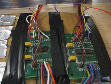
We first started with the construction of the capacitive touch sensor pad. Following Professor Land's advice, we made our capacitive touch pads out of aluminum foils and saran wraps. We created a 4 by 4 grid of 16 aluminum pads mirroring the 4 by 4 grid of LEDs. We soldered the first two columns to a Motorola capacitive touch sensor board and the last two columns to another sensor board since each capacitive touch sensor has only nine input channels. We also created two additional pads and wired up to the remaining input channels on both boards. The wiring schematic of the first two columns of electrodes is as shown below. The wiring schematic is exactly the same for the last two columns. A picture of the actual aluminum electrodes and the capacitive touch sensors is also shown below. Inputs E1-E9 on the capacitive touch sensor were connected to the aluminum electrodes. The watchdog function of the capacitive touch sensor was not needed therefore was connected to CLK to prevent a reset from being issued. AGND and GND pin were connected to a common ground. To power the capacitive touch sensor pin Vpwr was connected to the 12 V regulator. Pins A,B,C and D are selector inputs that control which electrode is active. They were connected to output ports on the Atmega64.
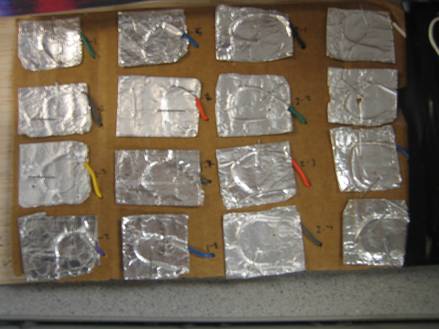
For more information about the board please refer to its datasheet in the Appendix section. The outputs (LEVEL pins) of the capacitive touch sensors were then wired to the ADC port of the Atmega64. We tested the capacitive touch sensors using hypertrm before moving on. There were a few problems with the sensors but we found out that the code that we were using to test was missing a few important syntaxes. Once the code was fixed, the capacitive touch sensors worked as expected. The output went low whenever one of the pads was touched. It is interesting to note that the capacitive touch pad work better without the saran wrap so we decided to remove all the saran wraps.
3.2 LEDs
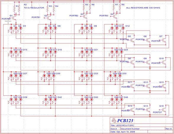
The construction of the LED circuit is the most difficult task on the hardware side. We chose to use tri-color LEDs with each having four leads one for the common anode and the rest for the individual colors (red, blue and green). In total the sixteen LEDs have forty-eight leads all together. As explained in the Rationale section, we employed the row and column arrangement and the schematic for the led circuit is shown below. Again the arrangement allows the use of smaller number of ports to control all of the LEDs and reduces the hardware needed. To turn on a led, one just connects the column that the target led is in to the 5V supply and ground its respective row. To turn on multiple LEDs, we employed software codes that turns on one led at a time at a rapid pace that the eyes cannot detect.
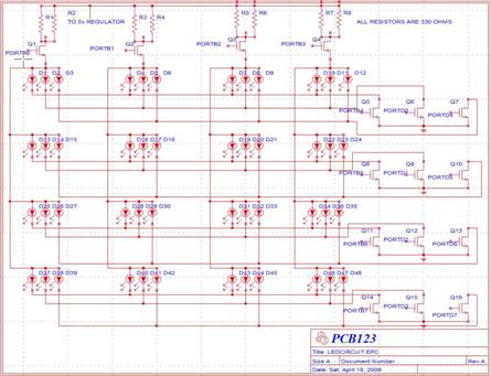
The LEDs were first assembled on two small protoboards with eight LEDs on each. All four leads of each led were then soldered to the protoboard. Next, the transistors were arranged and spaced out on a big protoboard to make sure that there were adequate room for all of the forty eight wires and plus. We carefully chose the locations of the transistors on the protoboard in a way that minimizes wires length. Before connecting the LEDs to the appropriate transistors, we first calculated the amount of current needed to power the LEDs. According to the data sheet of the LEDs, 30 mA is required to to light each tri-color led or 10 mA for each of its color. Since the LEDs are arranged four per column, each column then only requires about 30 mA. With each column is connected to 5 V that means that we need about 167 ohms of resistance. Each column is controlled by a p-mosfet transistor. Therefore we soldered each p-mosfet transistor to the 5 V source with a parallel combination of two 300 ohm resistors (giving 150 ohms of effective resistance) in series. Shown below is a general wiring pictorial of the transistors and regulators.
Next, we painstakingly soldered all of the same color led leads from the same row to a n-mosfet transistor. We repeated the same process for each color in each row and then the next rows. Extreme caution was taken during this stage, we made sure that each lead from each led is connected to the right transistor. In addition, we made sure that the pin on each transistor is connected to the right component. The pin out diagrams for the transistors and LEDs are shown below. It was extremely hard to solder the wires to the LEDs because of the huge number of connections and the small area available on the protoboards for soldering. Compounded to this is the problem that the soldering mask of the protoboards is not of the best of quality. They can be burned off completely if too much heat is applied. Finally the the base of each transistor is hooked up to a port on the MCU. These ports are used to turn on and off the LEDs. We used green wires to indicate connection for the green color portions of the tri-color LEDs, likewise red for the red portions and blue for the blue portions. We chose white for the common anodes. This standardized set of colors helped us tremendously with troubleshooting.
3.3 Power
Initially we looked into battery power but after checking the current requirement for the LEDs and the capacitive touch sensors we decided to use a power cable plug instead since batteries would be drained extremely quick given the current figure calculated. The power cable plug provided 12 V DC at 300 mA, which are enough to source the current needed to run both the LEDs and the capacitive touch sensor circuit. The LEDs need a supply voltage of 5 V with a total current of 120 mA for all four columns to light up. This was taken care of through the use of a 5V voltage regulator that had an input voltage range from 5 V to 20 V. The capacitive touch sensors each requires 12 V to operate were powered using a 12 V voltage regulator. Both regulators take in the 12 V DC that is also fed to the Atmega64 microcontroller board. The regulators were soldered and connected to the power bus on the big protoboard. Likewise, the ground pin of the Atmega64 board was chosen as the common ground for all of the circuit and was soldered to the ground bus on the main protoboard. We chose to use only red wires for power and brown for ground. This choice was for the ease of debugging it would make further down the road when we assemble everything together.
4
Software
4.1
Key
Press Detection
The keypad scanning was done using the functions task1() and scan(). Task1() is the scheduled function in the main loop, set to execute every 10 ms. It sets the address bits on PortC (ports 0-3) to the current scan address, and then delays by 30 microseconds. This is to prevent any propagation delay in the switch on the sensor from corrupting our ADC conversion of the sensor’s output. The datasheet did not specify the wait time for a valid output on the output pin, so we erred on the side of caution. After the delay, task1() calls scan(address), where address is the current address we are scanning. After control is returned to task1(), it increments the address count and checks if a complete cycle of the keypad has occurred. If a complete cycle has, then it resets the address counts and calls our main LED state control function, toggleLEDstate(), which will be explained later. Finally, task1() checks for a win condition for the game and calls wingame() if required.
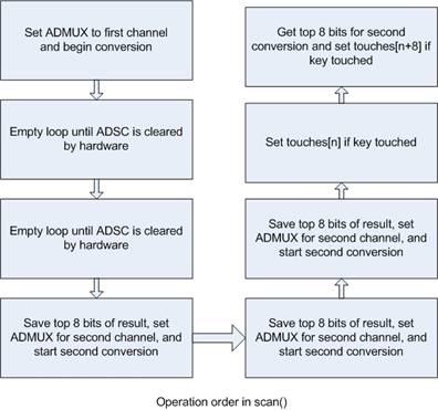
Scan() controls the ADC conversion of the inputs from the sensor boards, and then checks if the converted value matches our condition for a touch. The setting of ADMUX controls the reference voltage used, makes the conversion left adjusted, and sets the channel to either 0 or 1, depending on which input we want to look at. ADCSRA then starts the conversion. In order to ensure we get a valid conversion, we used an empty loop on ADCSRA to delay the program until the ADC conversion was done. This worked because ADCSRA stayed high until a conversion was done, and then was forced low by the hardware. After getting a conversion for the first channel, we switched the channel and started another conversion. While waiting for that conversion to complete, we analyzed the result of the first conversion by checking if it was lower than our threshold value of 10. If so, we marked the corresponding place for the current address in our state array so that our state machine for LED control could analyze it at the end of the scan cycle of all the keys. The same thing was then done for the second conversion, except that 9 was added to the address so that we would be manipulating the upper 8 LEDs.
4.2
LED
Control
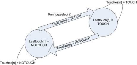
As stated before, toggleLEDstate() was called every 9 executions of the scan code in order to update the LEDs states. The input for a given scan cycle was fed into 18 state machines for debouncing, one for each key on the board. The states were based on the previous cycle’s detected level and transitioned based on the current cycled detected levels. When a button moved from the NOTOUCH to the TOUCH state, the corresponding game logic function toggleled<n>() (where n is the led’s address on the board) was called to change the specified LED and adjacent LED’s color state. Each button had a separate function that was called for this purpose. In addition to altering LED’s states, the two game command buttons, new game and playback, also had to be debounced. Each of these buttons had an identical state machine to the LED buttons, but instead of updating LED states, they called newgame() and solve().
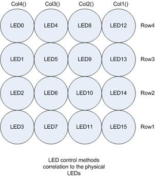
Switching LEDs on and off was done through the use of 16 functions that each changed the value of the correct output register on either Port B or D. Each column had its own function and each color in each row had a separate function. Calling these functions inverted the desired bit so that if the MOSFET controlling that row or column was on, it would be turned off, and vice versa.
In order to avoid the problem of unintentionally lighting LEDs when more than one LED was lit, we lit each column of LEDs separately. This control was done in the function displayUpdate(). We ended up having to light the red LEDs separately from the green and blue as well, because if a red LED was light in a column it would shut off any other colors. For each column, we called the column switching function, then went through each LED and checked if the state of that LED required a color to be displayed. If it did, then we switched on the specified color for that row. The LEDs were then held lit for 200 microseconds, which ensured the light had enough time to reach the user’s eye. We then repeated this process again exactly, which reversed whatever was switched on and returned our board to the off state. This was repeated three more times for each column.
4.3
Game
Logic
Once we recorded all the key pushes for a scan cycle, the software then had to translate these into game moves on the LED board. To accomplish this, we wrote state changing functions for each key that toggles the state of that key and each adjacent key (toggleled<n>()). Keeping these states as global states allowed them to be shared by all the functions, and be accessed by the displayUpdate().
Our game also employed two command functions triggered by two keys separate from the 4x4 keypad. The first was a new game function newgame(). This function reset all of the color states of the LEDs to off, and then randomly generated a new keypad. To generate new game boards, we read a bit from the EEPROM and used it to seed the random function rand(). We then called rand() and wrote the result back to that same bit in EEPROM, so on the next power on we had a random seed to use. The code to manipulate the EEPROM, as well as the right fuses to set, was found at “Society of Robots.com”, which is referenced below. In the newgame() function, we selected 25 random moves on the board to generate a new board. This was done for two reasons. First, a completely random game set up was not guaranteed to be solvable. If the board originally started blank however, we knew that any configuration we generated by making random moves would be solvable. We also saved the LED states for each step in this process for use in the solve() function.
In order to show the user how the board was generated, we wrote the solve() function. This command disables keypad input and plays in reverse how the current board’s initial configuration was generated. If this game were two states it would represent a solution to the board, but because we have four states we did not actually show the player a “true” solution. If a player hit each key three times in the order of moves that the board was generated, then this would compromise a solution. Displaying this would take three times as long, and we felt that the 25 frames we were showing was about as long as we wanted the playback feature to be. One interesting little addition to the playback is it allows the user to make the last winning move. This was initially by accident, but after fixing the mistake we felt that we wanted some user interaction at the end of the playback, so the “error” was added back in.
The last function we implemented was wingame(). This function disabled keypad input and displayed an animation to signify the player had cleared the board of lights. The animation was hardcoded in LED states in the WinArr array and cycled through using a for loop. In each loop the correct LED’s states are changed in order to progress the animation. After displaying the animation, a new board is automatically generated for the user. The check for a win (all lights out) occurs in the scanning schedule task, task1(). This win condition is calculated by doing a bitwise OR of all the LED states. If the result is 0, then it signifies that all the LED’s states are OFF.
5
Results
5.1 Hardware
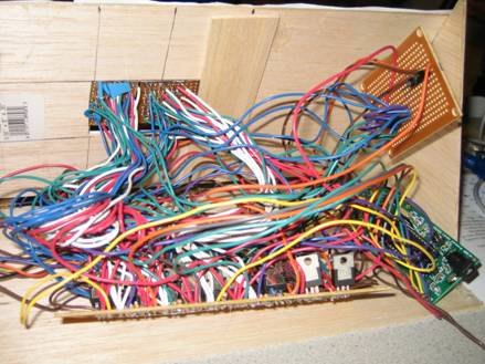
The huge number of connections and wires caused much confusion and chaos when it came time for troubleshooting. We ran into several hardware related problems mainly bad soldering joints. Making repair to these soldering joints were almost impossible since the soldering pads were of low quality. They vaporized instantaneously as soon as we applied heat for a repair soldering job. Several times this forced us to transfer an entire transistor circuit to another board making things even more confusing. In additions, the LEDs were arranged in a very tight grid causing occasional wires crossing, which shorted several LEDs. This problem was alleviated with a few pieces of electrical tapes and meticulous check and manual separation of wires.
Another major problem that we found was the common ground. We tested our project always having the STK500 plugged to it and the hardware worked as expected. However, when the STK500 is not plugged the two right column of capacitive touch fail to sense any touch. It turned out that our common ground is not a true effective ground. We sidestepped the problem by hooking up our common ground pin to a ground point on our working station. The station acts as a big ground and fixed our grounding issue.
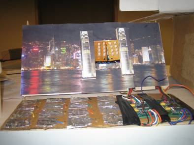
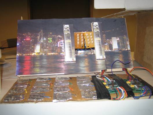
The final result after all of the repairs were made is a working sixteen tri-color led display responsive to sixteen capacitive touch inputs. Our final step in our hardware implementation was the fabrication of a housing unit that contains all of the messy circuits for the LEDs and the capacitive touch sensors. We used thin basalt boards and hot glue to make a nice panel. We cut a square hole in the middle for the 4 by 4 grid LEDs. For a nice presentation, we cut a print out of a nice background wallpaper and glued it to the panel. A picture of the final result is shown below.
5.2
Software
Overall, the software for this project performed as we expected. The LED control method produced no visible flicker, and the timing did not interfere with accurate keypad scanning. We were somewhat concerned about the transition period of the MC33794 capacitive touch sensor interfering with how we scanned the keypad, but we had no issues when using a delay of 30 microseconds between switching electrode addresses and reading the output of the sensor. The keypad appeared responsive to input, aside from the grounding issues we were having. The timing of the animations used were correct as well. The solve animation played at around 7/10’s of a second, and the win game animation at about half of that. The game logic performed well, as we never observed an incorrect state switch of any LED in the final design.
The one portion of the program that did not work as well as we had hoped was the random board generation. Even though we were seeding the random function with a random value from the previous power on of the board, we always got the same sequence of board configurations. Each generation of a new board was different than the last, but if you compared the boards to the last power on of the circuit they were the same. Our guess was that either our method of manipulating the EEPROM was incorrect or we were misunderstanding the random function’s seeding.
We found that the LED control code and keypad scanning code was surprisingly portable to other applications. This code was originally written to implement a drawing program, but we changed the goal of the project. After this change, we made very little modifications to the original LED control code besides changing what the behavior was when a key was pushed. The keypad scanning code did not change at all.
6
Conclusion
6.1
Analysis
of Design
Most of our design met our expectations. The capacitive touch sensor that seemed to have a better ground connection performed as we expected. It proved to be a responsive and inexpensive way to detect user input. The durability of the electrodes proved to be a concern, and if this design was to ever be used on a longer term basis it would require a redesign of the electrodes to be more resistant to breaking apart. The other capacitive sensor was somewhat of a disappointment. Sometimes it will work without the user holding on to a larger metal object or moistening their finger, but it seemed for smaller users they were required to do these things. If we remade this circuit, one priority would be providing a more reliable ground to both of the sensors.
The LEDs performed as we expected as well. The pulsing of the LEDs turned out to be a good thing, because the constantly lit LED was extremely bright and would be annoying to look at when playing the game. The colors they produced were easily distinguishable from one another and looked quite good. The wiring coming from the LED board was a lot messier than we would have liked, but we were able to hide it from the user using the balsa wood case.
Overall the wiring aspects of the design proved to be much trickier than we had planned for. When first setting up the project we did not modify our design to accommodate the large amount of connection that would be required for the LEDs and their controlling MOSFETS. The wire to wire solders on the LED board posed a risk of shorting and preventing the LEDs from lighting properly. Likewise, putting all the MOSFETs on one board proved to be somewhat disastrous as the solder pads kept tearing off from all the solders. If we built this project again we would definitely look into a PCB for the LEDs and their controlling switches to simplify the wiring and increase the reliability of the design.
Future additions to this project might include a better random board generating sequence, a true solving function that solves the current configuration of the board, and integrating the lighting into the touch pad so they would not be separate.
6.2
Intellectual
Property Considerations
We used the EEPROM code from the “Society of Robots” website. This code was simply a command to the Mega644 to save to the EEPROM and read from it, and thus was actually written by Atmel for their microprocessor, so we felt there were no copyright or patent issues with using the commands in our project. We also used some code from ECE 476 projects we worked on in class, originally written by the course staff.
We did not name our game the same thing as the Tiger Electronics version of this game called “Lights Out”. We also felt that there were enough differences between our implementation of the game and Tiger Electronics that we were violating no patents or copyrights. For example, their line of Lights Out games are portable, where as ours is stationary and is powered by a wall plug. The interface of Lights Out uses mechanical switches and integrates the lights into the buttons, where as ours is capacitive based and maintains a separate keypad and LED board. In addition, we made this game for education purposes and have no intention of competing with Tiger Electronics.
6.3 Ethical Consideration
IEEE's code of ethics was strictly followed at all times during the making of this project. We have been putting safety and health of the public as the number one priority in every decision that we made and every implementation stage of the project. We were never offered any form of bribery during the project, but if we were we would have rejected it. We encountered no conflicts of interest when developing the project, but if we had we would have disclosed them honestly. We followed every safety protocol during soldering and construction of our project. We made sure that credit is given where credit is due and properly noted any sources of contribution to our project. We have been holding ourselves to the highest standard of integrity by presenting the results and our work as honest as we could and providing all available data and evidences to support our results. We made every attempt to share our knowledge with our classmates and the public of our project. Most important of all, we welcomed and listened to all feedbacks from our fellow classmates and TAs and in doing so we were able to improve on our original project design and increased our technical knowledge a great deal.
7
Appendix
7.1
Commented
Code
7.2
Schematics

7.3
Cost
report
|
Part
Description |
Price
per unit |
Quantity |
Cost |
Comments |
|
Mega644 |
8.00 |
1 |
8.00 |
|
|
PC
Board |
5.00 |
1 |
5.00 |
|
|
Mega644
socket |
0.50 |
1 |
0.50 |
|
|
Freescale
MC33794 |
0.00 |
2 |
0.00 |
Donation |
|
RL5-RGB-D
(LEDs) |
1.49 |
16 |
23.84 |
|
|
IRF734 |
0.55 |
12 |
6.60 |
n-channel
mosfet |
|
BS250KL-TR1-E3 |
0.79 |
4 |
3.16 |
p-channel
mosfet |
|
Power
Supply |
5.00 |
1 |
5.00 |
Rented
from lab |
|
LM340-T5 |
0.67 |
1 |
0.67 |
5V
regulator |
|
LM340-T12 |
0.67 |
1 |
0.67 |
12V
regulator |
|
Resistors |
0.00 |
8 |
0.00 |
Provided
by lab |
|
Solder
board |
2.50 |
1 |
2.50 |
|
|
Small
solder board |
1.00 |
3 |
3.00 |
|
|
Aluminum
foil |
0.00 |
0 |
0 |
Previously
owned |
|
Staples |
0.00 |
0 |
0 |
Previously
owned |
|
Balsa
wood |
4.99 |
1 |
4.99 |
AC
Moore |
|
Cardboard |
0.00 |
0 |
0 |
Previously
owned |
|
Total
Cost |
63.93 |
7.4
Specific
tasks
The hardware design was jointly thought out by both Hung and Chris. The building of the hardware was overseen and performed by Hung. The development of the software for the project was overseen and performed by Chris. Debugging of both sides of the project was a joint venture.
7.5
References
7.5.1 Data
Sheets
- MC33794 Data sheet
- Mega644 datasheet
- NMOS data sheet
- PMOS data sheet
- Voltage regulator data sheet
- LED data sheet
7.5.2 Vendor
Sites
7.5.3 Background
sites
- Wikipedia (Lights Out background information)
- Math World (Lights Out information)
- http://www.societyofrobots.com/member_tutorials/node/309 (EEPROM code)
- 3D LED cube
We’d like to thank the generous staff of ECE476 for being patient and answering questions, sticking out those long nights in the Digital Design Lab with us, and in general being really awesome people.