ECE 4760 Final
Project
Chen Kiang Tang (ct269), Wanjing Loh (wl246), Wuhan
Desmond Cai (wc276)
Contents
1. Introduction
2.1 Rationale
2.2 Background Math
2.3 Logical Structure
2.4 Hardware/Software Tradeoffs
2.5 Standards
2.6 Patents, Copyrights, and Trademarks
3.1 Speech Synthesis
3.2 Force Sensor
3.3 Power Regulator 3.3V
3.4 Dataflash System
4.1 Software UART
4.2 Updating the Time
4.3 Updating the LEDs
4.4 Managing Keypad Inputs
4.5 Communication with Computer
4.6 Managing Alarms
4.7 Speaking
4.8 Laser State Machine
4.9 Force Sensor
4.10 PC Desktop GUI
4.11 SPI for DataFlash
5. Results
5.1 Accuracy of Clock
5.2 Concurrency of Execution
5.3 Safety of Design
5.4 Usability of Design
6. Conclusion
6.1 Analysis
6.2 Standards
6.3 Intellectual Property Considerations
6.4 Patent Opportunities
6.5 Publishing Opportunities
6.6 Ethical Considerations
7. Appendices
7.1 Appendix A: Commented Program Listing
7.2 Appendix B: DataFlash Program Listing
7.3 Appendix C: GUI Program Attachments
7.4 Appendix D: Schematics
7.5 Appendix E: State Machines
7.6 Appendix F: Budget
7.6 Appendix G: Member Tasks
We designed an intelligent alarm clock which can be
programmed from the computer to speak custom messages and also detect whether
the user is on his bed or leaving his room.
Sensors are pervasive in
industrial, aerospace, and medical fields. Although they can potentially enhance
the common person's everyday-life, they are still seldom used in most consumer
electronics. In line with future developments in technology, the purpose of our
final project is to integrate a range of sensors to improve the functioning of
an electronic necessity - the alarm clock. With current alarm clocks,
oversleeping is mostly dependent on the user's discipline. We vision that with
future alarm clocks, oversleeping will be a thing of the past as the alarm
clocks will be able sense whether the user has truly woken up. Also, while most
alarm clocks today only serve to wake the user in the morning, future alarm
clocks will be able to remind the user of various events in the day. Hence, we
developed a next-generation alarm clock which can be programmed from the
computer to speak customized alarms, sense whether the user is truly awake and
detect whether the user is in the room.
2. High Level
Design
2.1 Rationale
The main inspiration for
our project came from the fact that most college students oversleep on their
alarm. Personally, we know many people (ourselves included) who often oversleep
on their alarm. Such oversleeping occurs even with the presence of a snooze
function on the alarm as the exhausted sleeper, in a dreamy state, can easily
turn off the alarm unknowingly instead of snoozing it. While current innovative
alarm clocks usually use a physical impetus to wake the user (e.g. alarm clocks
which walk off the table, fly to a random location, or as created by previous
ECE 476 students, an alarm clock with a retractable button), we wanted to make a
more civil alarm clock. Psychological studies also show that people respond
better to alarms if their names are being called. Hence, we decided to make a
computer-programmable alarm clock with customized alarm speeches. Given the
pervasiveness of sensors today in high-tech applications, the use of laser and
force sensors as added features was a natural inclusion.
2.2 Background
Math
No background math is necessary to understand
our project.
2.3 Logical Structure
Our
alarm clock connects to a computer through the Serial-to-USB converter. In
addition, it also receives an input from a force sensor which lies underneath
the pillow, and two inputs from two photodiode-laser pairs at the entrance of
the room. The photodiode-laser pairs will be placed opposite each other so that
the alarm clock will be able detect when a user leaves the room.
2.4 Hardware/Software
Tradeoffs
There are few hardware/software
tradeoffs for our project as the MCU is the central component necessary for
interfacing with the computer and receiving inputs from the various sensors.
However, one tradeoff involved is in synthesizing speech manually using the
MCU versus using an external speech synthesizer. Using the MCU to
synthesize speech in software will require immense memory space and
computational complexity. Hence, we have decided to use an external speech
synthesizer as professional speech synthesis options are likely to produce
better quality speech and also free up our MCU computational capacity for the
other features like sensors and GUI communication.
Another tradeoff involved is in storing the alarm messages
in the data memory versus employing an external memory component. Assuming a
typical alarm message to be the size of a Short Messaging Service (SMS) message
of 160 characters, with the Mega644 having only 4kb of data memory, we will
only be able to store at most 25 alarms (this number might be further halved
since the application also uses data memory to store its variables). This is
short of what is needed for our alarm clock to become fully programmable and
support the user on multiple events everyday. Hence, we decided to store the
messages using a 4Mb Atmel dataflash chip. Unfortunately, the dataflash
chip malfunctioned on the day before the demo and we had to use the data memory
instead. By reducing the size of a message to 100 characters, our alarm clock
can store 20 messages.
2.5 Standards
The RS232 Standard is
automatically complied with by using already available C code. There are no
other standards our alarm clock has to comply with. We also used a Class 2 laser
which is safe for everyday use.
2.6 Patents, Copyrights, and
Trademarks
A brief search on the website of the
United States Patent and Trademark Office using "programmable alarm clock" did
not find any ideas which matched our idea. Current ideas usually involve a
physical feature like an alarm clock which moves off the table, hides in
random locations, etc.
3. Hardware Design
3.1 Speech
Synthesis
Current commercial speech synthesis options
cost upward of $30 and would easily cause us to blow our budget. Fortunately,
Kenneth from www.speechchips.com was kind enough
to sample us a pair of speech encoder (TTS256) and speech synthesis
(Magnevation Speakjet) chips. The TTS256 converts serial ascii text signals into
allophone codes in real-time to be interpreted by the Speakjet. The
encoder-synthesis pair enables us to incorporate text-to-speech functionality
without excessively burdening our main MCU. The output of the synthesizer is
filtered using a 2-pole low-pass filter before being passed into an audio
amplifier (an LM386-N-3). A trimpot between the low-pass filter and
the LM386-N-3 can be adjusted to control the volume of the alarm.
Finally, the output of the amplifier is passed into a 250uF blocking capacitor
to block out any DC signals before being connected to a pair of 8Ω
speakers.
3.2 Force
Sensor

An ideal force sensor will have to be able to detect the user regardless
of where he is lying on the bed. Our original intention was to use a long
strip of force sensing resistor which stretches across the bed. Unfortunately,
the cheapest such option we could find cost $18. Since we did not have the
budget for it, we decided to use Sensitronics' standard force sensing
resistor (FSR) sample. The sample is a sheet of multiple force sensing resistors
about 4cm by 4cm each. With such small force sensing resistors, it is
highly possible that we will not always be able to detect the user on the
bed and this implementation will be more of a proof-of-concept than
an actual implementation.
The resistance of the FSR varies according to the magnitude of force applied to it. When no force is applied to it, the resistance is extremely large so it acts almost like an open circuit. When a reasonably small force, equivalent to a button press, is applied, the resistance drops to about 500ohm. We used a simple voltage divider circuit to produce a signal for the MCU. When a force is applied to the FSR, the output will be near Vcc, which is equivalent to a logical high. When no force is applied, the output will be near ground, which is equivalent to a logical low. This way, we will eliminate the need for an analog to digital conversion (ADC) altogether.
In addition, when we tested the FSR by sitting on it on a
chair, we also discovered that the soft-sinking fabric reduced the net force
detected by the FSR. Hence, to ensure that the FSR can reliably detect a
person's weight, we modified the FSR by folding it in half to increase the
amount of flex when it is being pressed on.
3.3 Laser Door
Detection System

Our design for the laser door detection system is
similar to many home-made laser security systems that use lasers and photocells.
As we need to detect if the user has left or re-entered the room, we use two of
such laser-and-photocell systems in parallel. We chose to use common 650nm 5mW
lasers (A-H650-5.0-3 purchased from axiz.com) and a 12-30kΩ photodiode
(PDV-P5002). We can determine if the user has left or re-entered the room
by checking which of the two systems fire first. A photocell has a
resistance that varies with the intensity of light shining on it. Under ambient
light conditions in the lab, the resistance measured was about 6-7kΩ.
When our laser was shining on a photocell, the resistance dropped to
about 1.5kΩ.
We utilized a simple op-amp voltage comparator circuit which will output a high voltage (3.75V) when a laser is blocked and a low voltage (ground) when a laser is not blocked. We used a voltage divider circuit to produce a stable 3.67V for the non-inverting input. For the inverting input, we also used a voltage divider circuit with the photocell and a 10kΩ trimpot (set to about 6kΩ). When the laser is blocked, this voltage divider will output a voltage of about 2.5V, making the op-amp output a high voltage (3.75V). When the laser is not blocked, this voltage divider will output a voltage of about 4V, making the op-amp output a low voltage. Hence, this output can be read by the MCU as a logical high or logical low, eliminating the need for an ADC.
We used a power regulator (296-8056-5-ND) to provide the
required stable 3.3V for both lasers. In the previous design before the
failure of the dataflash system, a separate but similar 3.3 power regulator
is also used to provide power to the dataflash. The power regulator is
connected according to the schematic given in its datasheet.
3.5
DataFlash System
We used Atmel's
AT45DB041D 4Mb dataflash as our external memory. The dataflash system was
connected to the Serial Peripheral Interface (SPI) of the MCU. Although the
dataflash runs on a 2.7V-3.6V supply, it can receive SPI inputs directly from
our MCU which runs on a 5V supply. Hence, we only required two additional
components. One is the 3.3V (296-8056-5-ND) regulator for powering the
dataflash, and another is a translator (MAX3370) to convert the 3.3V output from
the dataflash into a 5V input to the MCU.
The dataflash system was
setup and functioning successfully till the day before the demo. While we are
still unable to isolate the problem, we suspect the cause to be a faulty power
supply causing huge spikes in the Vcc.

4. Software
Design
The speech encoder takes a serial input from the MCU. Since
the MCU UART is used for serial communication with the computer, a software UART
has to be programmed to generate the serial output to the encoder. AVR304: Half
Duplex Interrupt Driven Software UART was consulted for the sample code.
However, certain changes had to be made. The sample code given by AVR304 is
asynchronous with the main timer in that it turns off the main timer and turns
on a second timer each time a byte is to be sent. However, our alarm clock
requires the use of only the main timer at all times. Hence, the code is
modified to use the main timer synchronously for timing the software UART.
4.2 Updating the Time (UpdateTime(),
CheckDate())
Updating
the time. Due to the strict timing requirements of the software UART, we would
like to ensure that the previous ISR gets completed before the next ISR
begins. Hence, we kept the ISR as short as possible by incrementing
only 2 timers in the ISR and using the UpdateTime() method to poll the
numbers of cycles passed since the last UpdateTime() call. This ensures that our
time-keeping will be as accurate as possible. Whenever the time is updated, it
also calls SearchNormal() and SearchWeekly() (see 4.6 below) to check whether
the current time matches a stored alarm. If it is a new day, CheckDate() is
called to determine the new day-of-the-week. The algorithm for determining the
day-of-the-week for an arbitrary day is obtained from Wikipedia: Calculating
the Day of the Week.
4.3 Updating the LEDs (LEDUpdate(),
LEDUpdateH() and LEDreset())
The LEDUpdate() updates the
four 7-segment LEDs through the LED driver. It decides which LED display to
update and also handles the blinking of the LEDs. It calls LEDUpdateH() to
update a single LED display. LEDreset() is used to prepare LED driver
for the next input.
4.4 Managing Keypad Inputs (opUpdate() and
codeUpdate())
The keypad inputs are managed by opUpdate() and
codeUpdate(). opUpdate() state machine is in charge of checking keypad
input for operations like changing the day and month, the time of the day, as
well as setting and cancelling a temporary alarm. We used the keypad for these
features as we felt it would be cumbersome to use the computer to do such little
things. It then interfaces with codeUpdate() state machine to get the
4 digit values needed. If the user sets a new date, CheckDate() from 4.2 is also
called to determine the day-of-the-week.
The codeUpdate() state machine is idle until it is told to take in a 4
digit input by the opUpdate() state machine. It then takes in the next 4
button presses which are numbers (not �a�, �b�, �c�, �d� ,�*�or �#�) and passes
them to the opUpdate() state machine.
4.5 Communication with
Computer (receiveUpdate(), transmits(), putstr_int() and
getstr_int())
Communication
with the computer is handled by receiveUpdate() and transmits(). The
receiveUpdate() state machine is one of the most important state machines
in our design. It is in charge of
interpreting commands sent by the computer and together with the transmission
state machine, sends back the requested information as well as acknowledgements.
We did not really implement error checking as communication was not done over
hyperterm, and the cpu ensures only legitmate messages are sent. The
transmits() state machine simply waits for a Flag to be raised and the
transmission mechanism to be ready and then sends the appropriate
message.
4.6 Managing
Alarms (AlarmUpdate(), SearchNormal() and
SearchWeekly())
This AlarmUpdate() state machine is in charge of the alarm
system and its ringing. As mentioned in 4.2, every minute,
UpdateTime() checks through the list of valid normal and weekly alarms and
see if any of them are scheduled to ring this minute. If yes, the appropriate
flag is raised (NormalAlarmFlag and WeeklyAlarmFlag respectively) and the
message is loaded AlarmMessage. By setting AlarmFlag to 1, we can get the alarm
to ring and play the message stored in AlarmMessage.
AlarmUpdate() also
handles the snoozing and turning off the alarm based on inputs from the
photodiodes and force sensor. When an alarm sounds, the user can turn off the
alarm in two ways: (1) pressing the keypad, (2) walking out of the room. If the
user returns to bed after pressing the keypad, the alarm will be snoozed for 5
minutes. Otherwise, the alarm will be turned off permanently.
Alternatively, the alarm can be forcibly turned off by
holding a key for 5 seconds or more.
4.7 Speaking (speak())
The speak() method is
called to speak a single word. When a string of words are sent to the TTS, all
these words gets passed to the speakjet buffer and played back. There is no
way to stop the speakjet from playing back what is left in the buffer. Since we
will need to terminate the alarm in the middle of a sentence (e.g. when the user
leaves the room), the only way to do so will be to send individual words
separately. The speakjet speaking line will be monitored instead of the speakjet
ready line. The next word is sent whenever the speaking line is down. This way,
an alarm can be easily stopped by terminating the sending of the next
word.
4.8 Laser State
Machine (LaserDetect())
We have two lasers to be placed on the door of the room. When the
beam is broken on the detector, we get a 1 and when the light is shining, we get
a 0. This state machine detects if the person has left the room. If the person
has left the room when the alarm is ringing, the alarm will be turned off by
AlarmUpdate().
4.9 Force
Sensor
The force sensor outputs a 1 when there is pressure on it and 0 when
there is not, allowing us to easily keep track of whether the person is on the
bed. The status of the force sensor is passed to AlarmUpdate() to determine
whether to turn off the alarm. If the user returns to bed after pressing the
keypad (to turn of the alarm), the force sensor will detect this action and
automatically snooze the alarm for 5 minutes. This prevents people from
unintentionally turning off the alarm.
4.10 PC Desktop
GUI
We created a PC Desktop GUI to interface with the alarm clock,
as we felt using hyperterm was clunky and user-unfriendly. The program was
created using C# in Microsoft Visual Studio, using the WindowsForm template,
which allowed us to easily design a GUI. By typing in the COM port number, one can interface with the Alarm Clock
and obtain a list of currently stored alarms From there one can add and delete
alarms, and set the message spoken by the alarm clock. Error checking is
implemented to ensure that only valid data is sent to the alarm
clock.
Communication
with the MCU is done by a serial link through the RS232. We used the built-in
SerialPort to communicate with the MCU, though we added in a handshaking
protocol to ensure messages are correctly sent and received. To improve user friendliness, all
settings that do not differ from computer to computer (such as the baudrate) are
hard-coded into the program. As such, the user only has to specify the correct
COM port to use (Autodetection of the COM port was attempted, but was not
successfully implemented).
The normal alarms and weekly alarms are
created as classes in C#, and one list was created for each class. The two lists
of alarms are sorted to ensure that the earliest in chronological order was
always first, and that no two alarms can share the same timing.
4.11 SPI for
DataFlash
Code for the DataFlash was created by first consulting
AVR335: Digital Sound Recorder with AVR and DataFlash. The code had to be
modified because unlike the DataFlash used in AVR335, our DataFlash does not
have a ready bit output so the ready bit can only be obtained by polling the
status register in the DataFlash. In addition, we also need a method to read and
write individual pages instead of all the pages in AVR335.
5. Results
5.1 Accuracy of the clock
The
most important property of an alarm clock can have is to be able to keep
accurate time. As we needed to use the software ISR to run the software UART, we
could not afford to put extraneous code in the ISR. However, we also have to
keep track of the date, month and day of the week, a non-trivial task
considering that they may be set to invalid values by the user, such as January
60th. Furthermore, as we have alarms that can be set to ring once every week
(say Monday), we need to be able to calculate the day of the week whenever the
user changes the date. Our solution is to use the ISR as a timer, and keep track
of the number of times the ISR has run since we last called the method. This
allows us to keep track of time accurately but still allow the ISR to stay
short.
Hence, the only inaccuracy in our clock time will be that due to
rounding errors. There are 582524.271845 ISR calls in 1 minute. However, since
we took 582524 ISR calls to represent 1 minute, we gain 0.271845 ISR calls every
minute or 142881.732 ISR calls a year. This translates to 14.7 seconds a year,
which is tolerable for every-day use.
5.2 Concurrency of
execution
To ensure concurrency of execution, we created
many small state machine that update themselves during each cycle of the main
loop. This ensures that the program continues to run even when the user is
inputting commands.
5.3 Safety of the design
As
the components of our circuit (LEDs, lasers, speakers) draw a significant amount
of current, we decided a single power supply is not enough. Instead, we use two
separate power sources, one for the LEDs and lasers, and one for the speech chip
and speakers. This helped reduce the load on the each power supply, which had
caused problems for us in testing as it led to weird results during tests. As
mentioned above, we were careful with the lasers to avoid damaging people's
eyes. As there are many wires in our design, we packed all of them in a compact
box with only the required parts like the keypad and LED available. We also
wrapped up the photodiode to prevent users from being exposed to the chemicals
on the photodiode.
5.4 Usability of design
We
feel that our alarm clock is very easy to use. Without the computer, our alarm
clock works just like any other alarm clock, and should pose no challenge to
operate. The computer interface is simple to use and user friendly. Once set up,
most users will not have a problem operating it. The only problem is that we
were unable to implement the auto-detection of the COM port, and will require
users to input it manually, which might be a problem for technically challenged
people. However, when people plug in the USB to serial converter, Windows
usually notifies the user of the name of the COM port, so hopefully that
will mitigate the problem.
6. Conclusion
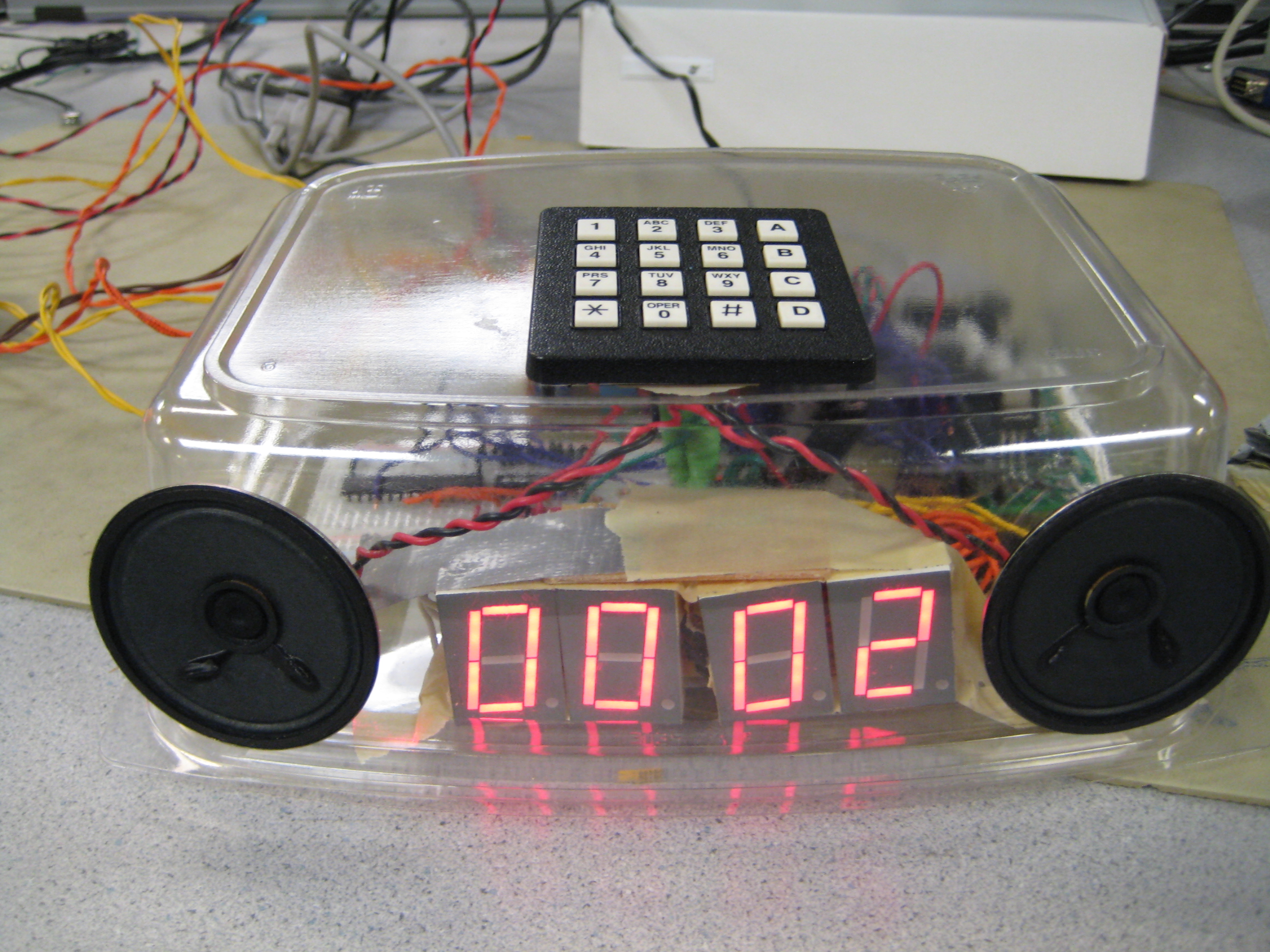
6.1 Analysis
Our final product is contained in a
transparent container which we salvaged. It has utilized all the keypad buttons
fully to provide usual alarm clock features (e.g. changing time, changing date,
viewing date, changing alarm, etc.) It is also easily programmable from the
computer. If the laser system is well-aligned before use and strongly affixed
with tape, it is highly accurate in detecting when a user leaves a room. The FSR
is accurate only if the user lies on it directly.
Hence, the project has
met most of our expectations in terms of the features. The only exceptions being
the small FSR and the limited memory due to the damaged dataflash on the day
before the demo. However, there are certain other aspects which we feel we could
have done better.
A lesson can be learnt from the failed DataFlash. The
DataFlash was a small and vulnerable piece of hardware that is easily damaged.
Hence, there should have been foresight to purchase additional DataFlash chips
in order to deal with such unforeseen circumstances at the last
minute.
If there were more time for this project, we would definitely
attempt to setup auto-detection of COM port (a feature present in AVR Studio).
This will greatly improve user-friendliness and be in line with plug-and-play
philosophy.
During the project, much precious time was spent debugging
hardware problems, the most time consuming problems being power related
problems. For example, we did not know that our setup requires two power
supplies until we met with a problem of oscillating Vcc which we could not
solve. Our speakers were draining too much current and consuming too much power
so our circuit must either be powered with a higher rated adaptor or use two
adaptors. In future, any circuit design with many components should definitely
consider the overall power rating in the design.
6.2 Standards
Since alarm clocks are not
regulated, there are no design standards for our alarm clock. Our laser is a
Class 2 laser, which is safe because the blink reflex of humans will limit the
exposure to no more than 0.25 seonds. Most laser pointers are Class 2. Moreover,
our lasers will be affixed near to the floor pointing horizontally and this
would definitely be safer than a normal laser pointer which can
be pointed in all directions.
6.3 Intellectual Property
Considerations
In our project, we made use of some code in the public domain. The
code is from the Atmel website, where they provide sample code to show how the
features on the Atmel chips could be used, for example how to use the dataflash,
the SPI interface, etc. We tested the sample code for the dataflash and the SPI
and then modified it for our own purposes.
We also looked at code in several C# tutorial websites to learn how
to build a GUI and utilize serial communication. However, we did not use the
code provided but designed our own based on the examples
shown.
Lastly, as we used C# to program our GUI, it requires Microsoft .Net
framework to run. It is freely available to download from the Microsoft
website, though the user still has
to install it.
We got samples from many
manufacturers, but we did not have to sign non-disclosure
agreements.
// -----------Intelligent Alarm Clock--------------
// ------ECE 4760 Final Project on Mega644---------
// ----------------Wanjing Loh---------------------
// ----------------Desmond Cai---------------------
// --------------Chen Kiang Tang-------------------
#include
<inttypes.h>#include
<avr/io.h>#include
<avr/interrupt.h>#include
<stdio.h>#include
<util/delay.h>#include
<string.h>#include
"uart.h"#include
<util/delay.h>// UART file descriptor
// putchar and getchar are in uart.c
FILE uart_str = FDEV_SETUP_STREAM(uart_putchar, uart_getchar, _FDEV_SETUP_RW);
//I like these definitions
#define
begin {#define
end }//timeout values for each task
#define
t1 288#define
blinktime 3; //=3#define
tenSec 10000#define
minute 60000#define
twoSec 2000//**********************************************************
// Software UART definitions
//**********************************************************
#define
TICKS2COUNT 206 // ISR calls between two bits.#define
ENABLE_TIMER_INTERRUPT( ) ( TIMSK0 |= ( 1<<OCIE0A ) )#define
DISABLE_TIMER_INTERRUPT( ) ( TIMSK0 &= ~( 1<<OCIE0A ) )#define
TX_PIN PD2 // Transmit data pin#define
TCCR TCCR0A // Timer/Counter Control Register#define
TCCR_P TCCR0B // Timer/Counter Control (Prescaler) Register#define
OCR OCR0A // Output Compare Register#define
TRXDDR DDRD // Transmit port direction register#define
TRXPORT PORTD // Transmit port#define
SET_TX_PIN( ) ( TRXPORT |= ( 1<<TX_PIN ) ) // Raise transmit pin: serial high#define
CLEAR_TX_PIN( ) ( TRXPORT &= ~( 1<<TX_PIN ) ) // Lower transmit pin: serial low//**********************************************************
// Speech production routines and variables
//**********************************************************
// Type defined enumeration holding software UART's state.
typedef
enum{
IDLE,
// Idle state, both transmit and receive possible.TRANSMIT,
// Transmitting byte.TRANSMIT_STOP_BIT,
// Transmitting stop bit.START_TRANSMIT
// Start transmitt}AsynchronousStates_t;
static
volatile AsynchronousStates_t state; // Holds the state of the UART.static
volatile unsigned char SwUartTXData; // Byte to be transmitted.static
volatile unsigned char SwUartTXBitCount; // TX bit counter.volatile
unsigned char transmit[264]; // Current word to be transmittedvolatile
unsigned char transmitIndex; // Index of next byte to be transmitted//**********************************************************
// Subroutines
//**********************************************************
void
initialize(void); // initializationsvoid
UpdateTime(void); // updates the time for the systemvoid
keyscan(void); // scans keypadvoid
debounce(void); // debounces keypadvoid
LEDUpdate(void); // updates LED displays through LED drivervoid
LEDUpdateH(unsigned char, unsigned char); // updates a single LED displayvoid
LEDreset(void); // resets LED drivervoid
codeUpdate(void); // registers a valid codevoid
opUpdate(void); // registers a valid codevoid
CheckDate(unsigned char, unsigned char, int);void
parseCommand(void); // parses a command sent by the computervoid
receiveUpdate(void);void
transmits(void); // sends to computervoid
getstr_int(void); // ready to get next string from serial linevoid
putstr_int(void); // ready to send next string to serial linevoid
SearchNormal(void); // searches for one-time alarmsvoid
SearchWeekly(void); // searches for weekly alarmsvoid
AlarmUpdate(void); // updates alarmsvoid
speak(void); // speaks the next wordvoid
LaserDetect(void); // detects changes in laser statevoid
ForceDetect(void); // detects changes in force sensor state//**********************************************************
// System variables
//**********************************************************
volatile
int time1; // task scheduling timeout countersvolatile
long time; // counts number of ISR calls since last call of time timeUpdate // creates a more accurate clock that updates its time according // to the exact number of cycleslong
cycles; // 1 second timerunsigned
char min, hour, day, month, weekday; // system timeint
year; //unsigned
char i,j; //for loop indices//**********************************************************
// keyscan variables
//**********************************************************
unsigned
char butnum; // if 0-11, corresponding button pressed, 12, no button pressedunsigned
char padin; //pin input from keypadunsigned
char keys[16] = {'1', '2', '3', 'a', '4', '5', '6', 'b', '7', '8', '9', 'c', '*', '0', '#', 'd'};unsigned
char keytbl[16]={0x77, 0x7b, 0x7d, 0x7e,0xb7, 0xbb, 0xbd, 0xbe,
0xd7, 0xdb, 0xdd, 0xde,
0xe7, 0xeb, 0xed, 0xee};
//**********************************************************
// debounce variables
//**********************************************************
unsigned
char dstate; // 0 no push // 1 maybepush // 2 pushed // 3 maybe releasedunsigned
char pressedbutnum;// currently debouncing this buttonunsigned
char key; // the registered character pressed (this has been debounced)unsigned
char pressedFlag; // 1 if a button is currently pressed//**********************************************************
// LEDUpdate variables
//**********************************************************
unsigned
char LEDTime[4]; // each entry contains a digit of the timeunsigned
char LEDTemp[4];unsigned
char LEDIndex; // current LED to updateunsigned
char ledOUT; // output to LED driverunsigned
char blink; // blink state: 1 means put a blankunsigned
char blinktimer; // blink timer to toggle blink state//**********************************************************
// codeUpdate variables
//**********************************************************
unsigned
char code[4]; // to store the four digits pressedunsigned
char cstate; // state of codeUpdate state machineunsigned
char keypadIndex; // index of current placeholder digit we are waiting forunsigned
char codeFlag; // flag to indicate four digits have been pressed//**********************************************************
// OpUpdate variables
//**********************************************************
unsigned
char tempA; // temporary calculationsunsigned
char tempB; // temporary calculationsunsigned
char ostate; // state of OpUpdate state machine//**********************************************************
// Checkdate variables
//**********************************************************
// for computing the day of the week given the date
unsigned
char monthDays[13]= {29,31,28,31, 30,31,30,31, 31, 30, 31, 30, 31};unsigned
char monthLookup[13]= {2, 0, 3, 3, 6, 1, 4, 6, 2, 5, 0, 3, 5};//**********************************************************
// UART routines and variables
//**********************************************************
void
getstr_int(void); //void
putstr_int(void);// RXC ISR variables
volatile
char r_index; // current string indexvolatile
char r_buffer[200];// input stringvolatile
char r_ready; // flag for receive donevolatile
char r_char; // current character// TX ISR variables
volatile
char t_index; // current string indexvolatile
char t_buffer[212];// output stringvolatile
char t_ready; // flag for transmit donevolatile
char t_char; // current charactervolatile
char echoCommand[16]; // output string// general transmission variables
unsigned
char rstate; // state of receive state machineunsigned
char tstate; // state of transmit state machineunsigned
char okFlag; // flag for sending "done"unsigned
char NAFlag; // flag for sending normal alarmunsigned
char WAFlag; // flag for sending weekly alarmunsigned
char sendIndex; // index of alarm being sent//**********************************************************
// Dataflash variables
//**********************************************************
//extern unsigned char pageRead[264]; // variable for reading and writing to flash
//unsigned int pageNum; // current page address to be used for next write
//**********************************************************
// Search normal alarm variables
//**********************************************************
unsigned
char NA[10][13]; // stores alarm in format yyyyMMddhhmmunsigned
char NA_Valid[10]; // stores valid flagunsigned
char NA_Message[10][100]; // stores address of message in dataflashunsigned
char mm;unsigned
char hh;unsigned
char dd;unsigned
char MM;unsigned
int yyyy;unsigned
char NormalAlarmFlag; // flag for playback of normal alarm messagechar
NormalAlarmMessage[100]; // store normal alarm message for playback//**********************************************************
// Search weekly alarm variables
//**********************************************************
unsigned
char WA[10][6]; // format Dhhmmunsigned
char WA_Valid[10]; // stores valid flagunsigned
char WA_Message[10][100]; // stores address of message in dataflashunsigned
char D; // hhmm are reusedunsigned
char WeeklyAlarmFlag; // flag for playback of weekly alarm messagechar
WeeklyAlarmMessage[100]; // store weekly alarm message for playback//**********************************************************
// Main alarm variables
//**********************************************************
unsigned
char alarmHour; // temp alarm hourunsigned
char alarmMin; // temp alarm minutesunsigned
char tempAlarmOn; // flag for temp alarm onchar
TempAlarmMessage[100]="E C E 4 7 6 0 \xda \xda \xda \xda \xda \xda \xda"; // temp alarm default messagechar
AlarmMessage[100]; // general alarm string. this must be stored before playbackunsigned
char AlarmFlag; // flag to turn on alarm at speak()unsigned
char astate; // state of alarm state machineunsigned
char pressedFlagTimer; // timer to determine a true off alarm press: 3 sec defaultunsigned
int SnoozeTimer; // snooze timer: 5min defaultunsigned
int onBedTimer; // timer to determine whether the user is still on his bed: 30 sec defaultunsigned
char EndFlag; // raised when alarm has stopped playingunsigned
int replayTimer; // for pausing between alarmsunsigned
char AlarmIndex; // index of next word to say;//**********************************************************
// Bed sensor force detection variables
//**********************************************************
unsigned
char onBed; // true if the user is on his bed//**********************************************************
// Door laser detection variables
//**********************************************************
unsigned
char innerLaser; // input from inner laserunsigned
char outerLaser; // input from outer laserunsigned
char lstate; // state of laser detection state machineunsigned
char LeaveFlag; // flag to indicate the guy has left the room//**********************************************************
// Timer 0 overflow ISR
// Main ISR for the system.
// Only one timer ISR will be used because of the timing
// requirements of the software UART
ISR (TIMER0_COMPA_vect)
begin
//increment system time: 9708.737864 counts = 1 sectime++;
//Decrement the timers if they are not already zero if (time1 > 0) --time1; //--------------------------------------------------------- //----Software UART for controlling the speech encoder----- //--------------------------------------------------------- switch (state){
//Send start bit case START_TRANSMIT:CLEAR_TX_PIN();
// Send start bitSwUartTXData = transmit[transmitIndex++];
// Put byte into TX buffer.SwUartTXBitCount = 0;
// Initialise bit counterstate = TRANSMIT;
// Move to transmit state break; //Transmit Byte. case TRANSMIT: if( SwUartTXBitCount < 8 ) // If there is a bit to send, send the bit.{
if( SwUartTXData & 0x01 ) // If the LSB of the TX buffer is 1:{
SET_TX_PIN();
// Send a logic 1 on the TX_PIN.}
else // Otherwise:{
CLEAR_TX_PIN();
// Send a logic 0 on the TX_PIN.}
SwUartTXData = SwUartTXData >> 1;
// Bitshift the TX buffer andSwUartTXBitCount++;
// Increment TX bit counter.}
else // Otherwise, send stop bit.{
SET_TX_PIN();
// Output a logic 1. if (transmit[transmitIndex] != '\0') // If next character is not an end-of-line, transmit next byte{
state = START_TRANSMIT;
// Go to transmit state}
else // Otherwise:{
state = IDLE;
// Go back to idle.}
}
break; //Idle. Not transmitting case IDLE: break; // Unknown state. default:state = IDLE;
// Error, should not occur. Going to a safe state.}
end
//**********************************************************
// UART character-ready ISR
// builds a string and signals when the string is complete
// supports backspace
ISR (USART0_RX_vect)
begin
r_char = UDR0;
//get a char //build the input string if (r_char != '\r') // Is the input a <enter>?begin
if (r_char == '\b') // Is the input a backspace?begin
putchar(
' '); // erase the character on the screenputchar(
'\b'); // backup--r_index;
// wipe a character from the stringend
else r_buffer[r_index++] = r_char; // add a character to the stringend
else // computer sent <enter>begin
r_buffer[r_index] = 0x00;
// zero terminater_ready = 1;
// signal cmd processorUCSR0B ^= (1<<RXCIE0);
// stop rec ISR -- clear rxcend
end
//**********************************************************
// UART xmit-empty ISR
ISR (USART0_UDRE_vect)
begin
t_char = t_buffer[++t_index];
if (t_char == 0) // end of string?begin
UCSR0B ^= (1<<UDRIE0) ;
// kill isr -- clear tx enablet_ready = 1;
// transmit doneend
else UDR0 = t_char; //send the charend
//**********************************************************
// Entry point and task scheduler loop
int
main(void)begin
initialize();
// main task scheduler loop -- never exits! while(1)begin
keyscan();
UpdateTime();
receiveUpdate();
transmits();
if (time1 == 0) // do these all the timebegin
time1 = t1;
debounce();
// debounces keypadLEDreset();
speak();
AlarmUpdate();
// updates the alarmLEDUpdate();
LaserDetect();
ForceDetect();
if (AlarmFlag ==0 && astate ==0) // do these only when no alarmbegin
opUpdate();
// updates state of input from keypadscodeUpdate();
end
end
end
end
//**********************************************************
// Updates time
void
UpdateTime()begin
cycles = cycles + time;
time =0;
if (cycles > 582524) {// 1 min has passedcycles = cycles - 582524;
min++;
if (min > 59){ // 1 hour has passedmin = min - 60;
hour++;
if (hour > 23) { // one day gonehour = hour - 24;
day++;
CheckDate(day, month, year);
}
}
SearchNormal();
// new min, search for possible alarmSearchWeekly();
}
end
//**********************************************************
//Scans the keys and extracts the key pressed
void
keyscan(void)begin
//get lower nibbleDDRC = 0x0f;
PORTC = 0xf0;
_delay_us(5);
padin = PINC;
//get upper nibbleDDRC = 0xf0;
PORTC = 0x0f;
_delay_us(5);
padin = padin | PINC;
//find matching keycode in keytbl if a valid button was pressed if (padin != 0xff) { //PORTB = padin; for (butnum=0; butnum<16; butnum++) { // if loop runs to the end, then there was no valid press so let butnum = 12 if (keytbl[butnum]==padin) { break;}
}
}
else butnum = 16; // no valid button pushedend
//end keyscan//**********************************************************
//State machine to debounce keypresses
void
debounce(void)begin
switch (dstate)begin
case 0: // no valid press was detected if (butnum == 16) { // still no pressdstate = 0;
}
else { // valid press was initially detecteddstate = 1;
pressedbutnum = butnum;
}
break; case 1: // valid press was initially detected if (butnum == pressedbutnum) { // same button is still pressed, register the press, move to debounce release statedstate = 2;
pressedFlag = 1;
// tell codeUpdate a button is currently pressedkey = keys[pressedbutnum];
}
else { // button is now not pressed, false calldstate = 0;
}
break; case 2: // no button release was detected if (butnum == pressedbutnum) { //still no releasedstate = 2;
}
else { // valid release was initially detecteddstate = 3;
}
break; case 3: // button release was initially detected if (butnum == pressedbutnum ) { // button is now no released, false calldstate = 2;
}
else { // wait for next pressdstate = 0;
pressedFlag = 0;
// tell codeUpdate a button is no longer pressed}
end
end
//**********************************************************
// Updating the LED time display through LED driver
void
LEDUpdate(void)begin
// A3..0 = digit to be outputted; // A5..4 = chip select // A6 = enable; // LEDUpdateH(2, 3);LEDIndex++;
if (LEDIndex >= 4) LEDIndex =0; if (astate == 0 && cstate) // if not alarm state and waiting for keypad input,{
// show input and blink relevant digit if (keypadIndex == LEDIndex) // if blink digit is the same as currently updating digit{
// blink by updating blink timersblinktimer++;
if (blinktimer > 3){
blinktimer = 0;
if (blink) blink = 0; else blink = 1;}
if (blink) // time to disappear{
LEDUpdateH(LEDIndex,15);
// put a blank in}
else // time to show{
LEDUpdateH(LEDIndex,code[LEDIndex]);
// put in current value}
}
else // otherwise, if sounding alarm or not waiting for keypad input{
LEDUpdateH(LEDIndex,code[LEDIndex]);
// put in current value}
}
else if (ostate == 4) {// display date and month // ensure value is correctLEDTemp[0] = month /10;
LEDTemp[1] = month %10;
LEDTemp[2] = day /10;
LEDTemp[3] = day %10;
LEDUpdateH(LEDIndex,LEDTemp[LEDIndex]);
}
else if (ostate == 5) {// display date and month // ensure value is correctLEDTemp[0] = alarmHour /10;
LEDTemp[1] = alarmHour %10;
LEDTemp[2] = alarmMin /10;
LEDTemp[3] = alarmMin %10;
LEDUpdateH(LEDIndex,LEDTemp[LEDIndex]);
}
else{
// ensure time is correctLEDTime[0] = hour /10;
LEDTime[1] = hour %10;
LEDTime[2] = min /10;
LEDTime[3] = min %10;
// print out timeLEDUpdateH(LEDIndex, LEDTime[LEDIndex]);
}
end
//**********************************************************
// Updates the LED drivers for a single LED display
void
LEDUpdateH(unsigned char digit03, unsigned char number)begin
unsigned char flipped = 3 - digit03;ledOUT = (flipped<<4) | (number);
PORTA = ledOUT;
//latch result in flipped with value numberend
//**********************************************************
// Resets LEDs to be rdy for next input
void
LEDreset(void)begin
PORTA = ledOUT ^ 0x80;
end
//**********************************************************
// State machine to interpret general key presses
void
opUpdate(void)begin
switch (ostate)begin
case 0: // waiting for user to select a command by pressing abcd if (pressedFlag == 1) { // debounced press detected //find out what button is pressed if (key == 'a'){ // get rdy to set time // display time on 7 segment // set index to zero, blink first digit // go to appopriate stateostate = 1;
cstate = 1;
break;}
if (key == 'b'){ // get rdy to set month and day // display month and day on 7 segment // set index to zero, blink first digit // go to appopriate stateostate = 2;
cstate = 1;
break;}
if (key == 'c'){ // get rdy to set alarm // display current alarm time on 7 segment // set index to zero, blink first digit // go to appopriate stateostate = 3;
cstate = 1;
break;}
if (key == 'd'){ // cancel temp alarmtempAlarmOn =0;
ostate = 0;
break;}
if (key == '*'){ // display the day and monthostate = 4;
break;}
if (key == '#' && tempAlarmOn ==1){ // display the temp alarm timeostate = 5;
break;}
}
break; // number pressed or nothing pressed // for all these cases, wait for codeFlag to be 1 which occurs when we have our 4 digit code or its canceled case 1: //setting time if (codeFlag ==1){//4 digit number readytempA = code[0]*10 + code[1];
// holds the hourtempB = code[2]*10 + code[3];
// holds the min if (tempA <= 23 && tempB <= 59) { // check for valid values TO BE WRITTENhour = tempA;
min = tempB;
SearchNormal();
SearchWeekly();
}
codeFlag=0;
ostate =0;
}
// stay in this state till the four digits are entered break; case 2: // setting month and day if (codeFlag ==1){//4 digit number readytempA = code[0]*10 + code[1];
//holds the monthtempB = code[2]*10 + code[3];
// holds the dayCheckDate(tempB, tempA, year);
// check for valid values TO BE WRITTENSearchNormal();
SearchWeekly();
codeFlag=0;
ostate =0;
}
// stay in this state till the four digits are entered break; case 3: // setting alarm //set alarm if (codeFlag ==1){//4 digit number readytempA = code[0]*10 + code[1];
// holds the hourtempB = code[2]*10 + code[3];
// holds the min if (tempA <= 23 && tempB <= 59) { // check for valid values TO BE WRITTENalarmHour = tempA;
alarmMin = tempB;
tempAlarmOn = 1;
SearchNormal();
SearchWeekly();
}
codeFlag=0;
ostate =0;
}
// wait here till we finish entering stuff break;; case 4: //display day and month if (pressedFlag ==0) {ostate =0;
}
break; case 5: //display temp alarm time if set if (pressedFlag ==0) {ostate =0;
}
break;end
// end switchend
// end OpUpdate//**********************************************************
// Handles updates of time, date, alarm, through keypad
// Only runs when waiting for user's number inputs
void
codeUpdate(void)begin
switch (cstate)begin
case 0: // not waiting for anything ignore keycodes break; case 1: // just received an operation and waiting for 4 numbers for (keypadIndex = 0; keypadIndex <4; keypadIndex ++){code[keypadIndex] = 0;
}
keypadIndex = 0;
// resets current keypad slotcodeFlag = 0;
// reset codeFlag as the 4 numbers are not readycstate =2;
// go to state 2 to wait for 4 numbers break; case 2: // waiting for a button pressed if (keypadIndex >= 4){ // four numbers obtained, can exitcodeFlag =1;
cstate =4;
break;}
if (pressedFlag){ if (key == '*' || key == '#') { // invalid key pressed, ignorecstate = 3;
break;}
if (key - 48 < 10){ // number pressedcode[keypadIndex] = key-48;
keypadIndex++;
// increments current keypad slotcstate = 3;
}
else { // otherwise, an invalid key was pressed, do nothingcstate = 3;
// resets current keypad slot}
}
break; case 3: // waiting for a button to be unpressed if (pressedFlag == 0){cstate = 2;
}
else { // button still pressed, do nothingcstate = 3;
}
break; case 4: // 4 digit code obtained if (codeFlag ==0) cstate = 0; //finished implementing the code break;end
// end switchend
// end code update//**********************************************************
// Checks for valid date and sets day of week accordingly,
void
CheckDate(unsigned char newday, unsigned char newmonth, int newyear)begin
// Step 1 check for leap year unsigned char leap; //leap year is divisible by 4, not divisible by hundred unless divisble by 400leap = (newyear % 4 ==0);
leap = leap && ((newyear % 100 !=0) || ((newyear%100 ==0) && (newyear % 400 ==0)));
// Step 2, check for valid date unsigned char valid;valid = 0;
if (newday ==0) newday =1; if (newmonth == 0) newmonth=1; while (!valid) { //LOOP till we get a valid date if (newmonth < 13){ // month is correct if (leap && newmonth == 2) { //feb of a leap year if (newday <= monthDays[0]) valid =1;// less than 29 days else { //increment the month and change the date to follownewday = newday- monthDays[0];
newmonth++;
}
}
else { //regular month if (newday <= monthDays[newmonth]) valid =1;// less than days in the month else { //increment the month and change the date to follownewday = newday- monthDays[newmonth];
newmonth++;
}
}
}
else { //too many monthsnewmonth = newmonth -12;
newyear++;
leap = (newyear % 4 ==0);
leap = leap && ((newyear % 100 !=0) || ((newyear%100 ==0) && (newyear % 400 ==0)));
}
}
// end loopyear = newyear;
month = newmonth;
day = newday;
// we have a valid date, start calulating day of week unsigned char c, y, m, yy;c = 2* (3-(newyear/100) %4);
yy = (newyear % 100);
y = yy/4;
m = (leap && newmonth <=2)? monthLookup[newmonth] -1:monthLookup[newmonth];
weekday = ((c + y + yy +m + newday) %7);
// 0 is sundayend
//**********************************************************
// Non-blocking keyboard input: initializes ISR-driven receive.
// This routine merely sets up the ISR, which then
// does all the work of getting a command.
void
getstr_int(void)begin
r_ready=0;
// mark string as not readyr_index=0;
// reset index // turn on receive ISRUCSR0B |= (1<<RXCIE0);
end
//**********************************************************
// Nonblocking print: initializes ISR-driven transmit.
// This routine merely sets up the ISR, then
// sends one character, The ISR does all the work.
void
putstr_int(void)begin
t_ready=0;
// mark transmitter as busyt_index=0;
// reset index // see if there is actually a string if (t_buffer[0]>0)begin
// if so, send one chararcterputchar(t_buffer[0]);
// and turn on transmit (UDR empty) ISRUCSR0B |= (1<<UDRIE0);
end
end
//**********************************************************
// parses the command obtained from the computer
void
parseCommand(void)begin
if (r_buffer[0] == 'L' && r_buffer[1] == 'A') // load all normal alarms from MCU to computer{
rstate = 1;
//okFlag = 1;getstr_int();
}
if (r_buffer[0] == 'L' && r_buffer[1] == 'W') // load all weekly alarms from MCU to computer{
rstate = 2;
//okFlag = 1;getstr_int();
}
if (r_buffer[0] == 'S' && r_buffer[1] == 'A') // store all normal alarms from computer to MCU{
rstate = 3;
okFlag =1;
getstr_int();
}
if (r_buffer[0] == 'S' && r_buffer[1] == 'W') // store all weekly alarms from computer to MCU{
rstate = 4;
okFlag =1;
getstr_int();
}
end
//**********************************************************
// Giant state machine in charge of receiving and decoding
// transmissions
void
receiveUpdate(void)begin
switch (rstate)begin
case 0: // waiting for opcommand from cpu if (r_ready) // we have an opcode{
parseCommand();
// parses command, set state to correct state}
break; case 1: // LA receivedsendIndex = 0;
rstate = 9;
// transmits all normal alarms one by oneNAFlag =1;
break; case 2: // LW receivedsendIndex = 0;
rstate = 10;
// transmits all weekly alarmsWAFlag =1;
break; case 3: // SA receivedrstate = 5;
sendIndex = 0;
//previous dataflash code
// pageNum=0; // resets starting memory page address to 0
//erase the table in preparation by setting all entries to invalid for (i=0; i<10; i++){NA_Valid[i] = 0;
}
// list of normal alarms coming up break; case 4: // SW receivedrstate = 7;
sendIndex = 0;
//erase the table in preparation by setting all entries to invalid for (i=0; i<10; i++){WA_Valid[i] = 0;
}
// list of weekly alarms coming up break; case 5: // list of normal alarms coming, next message is the date info if (r_ready){
//check if we are done if (r_buffer[0] == 'E' && r_buffer[1] == 'N'){
rstate = 0;
sendIndex = 0;
}
else{
//r_buffer contains the date infoNA_Valid[sendIndex] =1;
for (i =0; i<13; i++){
NA[sendIndex][i] = r_buffer[i];
}
rstate =6;
}
// get ready to receive the next msggetstr_int();
// send an ok signalokFlag=1;
}
break; case 6: // list of normal alarms coming, next message is the alarm message if (r_ready){
//previous dataflash code // store r_buffer in memory address //write_page_to_flash(r_buffer, pageNum); //store address in NA_Messagesprintf(NA_Message[sendIndex], r_buffer);
//previous dataflash code //NA_Message[sendIndex] = pageNum++;sendIndex++;
rstate = 5;
getstr_int();
// send an ok signalokFlag =1;
}
break; case 7: // list of weekly alarms coming, next message is the weekday and time info if (r_ready){
//check if we are done if (r_buffer[0] == 'E' && r_buffer[1] == 'N'){
rstate = 0;
sendIndex = 0;
}
else{
//r_buffer contains the date infoWA_Valid[sendIndex] =1;
for (i =0; i<6; i++){
WA[sendIndex][i] = r_buffer[i];
}
rstate =8;
}
// get ready to receive the next msggetstr_int();
// send an ok signalokFlag =1;
}
break; case 8: // list of weekly alarms coming, next message is the alarm message if (r_ready){
// store r_buffer in memory address //previous dataflash code //write_page_to_flash(r_buffer, pageNum); //store address in NA_Address //WA_Address[sendIndex] =pageNum++;sprintf(WA_Message[sendIndex], r_buffer);
sendIndex++;
rstate = 7;
getstr_int();
// send an ok signalokFlag=1;
}
break; case 9: //LA received, sending the list of normal alarms if (r_ready){
if (r_buffer[0] == 'N' && r_buffer[1] == 'E') // CPU is ready for next alarm{
sendIndex++;
//send next normal alarmNAFlag =1;
getstr_int();
}
if (r_buffer[0] == 'E' && r_buffer[1] == 'N') // CPU acknowledges all alarms sent{
okFlag =1;
//acknowledgerstate =0;
// go back to initial stagegetstr_int();
//wait for next str;}
}
break; case 10: //LW received, sending the list of weekly alarms if (r_ready){
if (r_buffer[0] == 'N' && r_buffer[1] == 'E') // CPU is ready for next alarm{
sendIndex++;
//send next weekly alarmWAFlag=1;
getstr_int();
}
if (r_buffer[0] == 'E' && r_buffer[1] == 'N') // CPU acknowledges all alarms sent{
okFlag =1;
//acknowledgerstate =0;
// go back to initial stagegetstr_int();
//wait for next str;}
}
break;end
// end switchend
// end code update//**********************************************************
//Handles transmits
void
transmits(void)begin
if(t_ready) { // can transmit a new line switch (tstate)begin
case 0: //nothing to transmit if (okFlag == 1){ //sends an oktstate =1;
break;}
if (NAFlag == 1) { //go into the state for sending normal alarm)tstate =2;
break;}
if (WAFlag == 1) { //go into the state for sending weekly alarmststate =3;
break;}
break; case 1: // transmitting okokFlag = 0;
sprintf(t_buffer,
"%s", "done") ;putstr_int();
tstate = 0;
break; case 2: //transmitting NANAFlag =0;
//clear the flag if (NA_Valid[sendIndex]) // valid alarm{
//previous dataflash code //load alarm message into alarm //read_page(NA_Address[sendIndex]);sprintf(t_buffer,
"%s%s", NA[sendIndex], NA_Message[sendIndex]);putstr_int();
tstate =0;
}
else //alarm is invalid{
tstate =1;
// tell cpu we sent all the alarms}
break; case 3: //send weekly alarmWAFlag =0;
//clear the flag if (WA_Valid[sendIndex]) // valid alarm{
//previous dataflash code //load alarm message into alarm //read_page(WA_Address[sendIndex]);sprintf(t_buffer,
"%s%s", WA[sendIndex], WA_Message[sendIndex]);putstr_int();
tstate =0;
}
else //alarm is invalid{
tstate =1;
// tell cpu we sent all the alarms}
break;end
}
end
//**********************************************************
// searches Normal Alarm table for possible alarm
void
SearchNormal()begin
for (i=0; i<50; i++){ if (NA_Valid[i] ==0) break; //an invalid entry found, break loop //go through NA table //check hh and mm first as most likely to be wrongmm = ((NA[i][10] -48) *10) + (NA[i][11] -48);
hh = ((NA[i][8] -48) *10) + (NA[i][9] -48);
if (hour == hh && mm ==min){ // hour and min are correct check day, month, year)dd = ((NA[i][6] -48) *10) + (NA[i][7] -48);
MM = ((NA[i][4] -48) *10) + (NA[i][5] -48);
yyyy = ((NA[i][0] -48) *1000) + ((NA[i][1] -48) *100)+ ((NA[i][2] -48) *10) + (NA[i][3] -48);
if (day == dd && month == MM && year == yyyy) {NormalAlarmFlag = 1;
//previous dataflash code //extract and set alarm message to be added //read_page(NA_Address[i]);sprintf(NormalAlarmMessage,NA_Message[i]);
break; // cos we are done}
}
// not equal, go on to next entry in list}
end
//**********************************************************
// searches Weekly Alarm table for possible alarm
void
SearchWeekly()begin
for (i=0; i<50; i++){ if (WA_Valid[i] ==0) break; //invalid entry found, break loop //go through WA table //check hh and mm first as most likely to be wrongmm = ((WA[i][3] -48) *10) + (WA[i][4] -48);
hh = ((WA[i][1] -48) *10) + (WA[i][2] -48);
D = (WA[i][0] -48);
if (hour == hh && mm ==min && D == weekday){WeeklyAlarmFlag = 1;
//previous dataflash code //extract and set alarm message to be added// read_page(WA_Address[i]);
sprintf(WeeklyAlarmMessage,WA_Message[i]);
break; // cos we are done}
// not equal, go on to next entry in list}
end
//**********************************************************
// InCharge of the Alarm
void
AlarmUpdate()begin
switch (astate)begin
case 0: // waiting for alarm to go off // check temp alarm, normal alarms, weekly alarms in order if (tempAlarmOn ==1 && min == alarmMin && hour == alarmHour){tempAlarmOn =0;
AlarmIndex = 0;
sprintf(AlarmMessage, TempAlarmMessage);
AlarmFlag = 1;
astate = 1;
// set alarm message to pass break;}
if (NormalAlarmFlag ==1){NormalAlarmFlag =0;
AlarmIndex = 0;
sprintf(AlarmMessage, NormalAlarmMessage);
AlarmFlag = 1;
astate = 1;
break;}
if (WeeklyAlarmFlag ==1){WeeklyAlarmFlag =0;
AlarmIndex = 0;
sprintf(AlarmMessage, WeeklyAlarmMessage);
AlarmFlag = 1;
astate = 1;
break;}
break; case 1: // alarm is on and playing // if button pressed, turn off alarm if (pressedFlag ==1) {pressedFlagTimer =0;
SnoozeTimer =0;
onBedTimer=0;
AlarmFlag =0;
astate = 2;
//wait to ensure the guy is really up before turning alarm off break;}
// if leave the room, turn off alarm if (LeaveFlag ==1){AlarmFlag =0;
astate =0;
}
// if alarm ends, replay alarm if (EndFlag) {EndFlag=0;
AlarmFlag =0;
astate =3;
}
break; case 2: //psuedo snooze state if (LeaveFlag ==1){AlarmFlag =0;
astate =0;
}
// if you pressed button for 3 secs immediately turn it off if (pressedFlag) {pressedFlagTimer++;
}
if (pressedFlagTimer == 100){
astate =0;
break;}
// if you went back to bed after pressing the button its a snooze // alarm rings again after 30 secs if (onBed){
onBedTimer++;
}
if (onBedTimer == 1000){astate =4;
break;}
// if you didn't go back to bed, alarm turns offSnoozeTimer++;
if (SnoozeTimer >= 10000){astate = 0;
break;}
break; case 3: // alarm has stopped playing if (pressedFlag ==1) {pressedFlagTimer =0;
SnoozeTimer =0;
onBedTimer=0;
AlarmFlag =0;
astate = 2;
//wait to ensure the guy is really up before turning alarm off break;}
// if leave the room, turn off alarm if (LeaveFlag ==1){AlarmFlag =0;
astate =0;
}
replayTimer++;
if (replayTimer > 300 ){ // wait 9 secs //reset alarmIndex and play alarmAlarmIndex =0;
AlarmFlag =1;
astate =1;
}
break; case 4: //alarm is in snooze, wait for 5 mins and then let it ring againSnoozeTimer++;
if (SnoozeTimer > 10000){astate = 1;
AlarmIndex =0;
AlarmFlag =1;
}
if (LeaveFlag ==1){AlarmFlag =0;
astate =0;
}
// if you pressed button for 3 secs immediately turn it off if (pressedFlag) {pressedFlagTimer++;
}
if (pressedFlagTimer == 100){
astate =0;
}
break;end
end
//**********************************************************
// State machine for pausing after each word. Necessary to
// enable speech to be turned off in the middle of a sentence
void
speak(void){
if (AlarmFlag && !EndFlag) // if an alarm is to be sounded that has not been sounded{
if ( (~PIND & 0x08) && (state == IDLE) ) // if the speakjet is not speaking and we are not sending it any data{
int i = 0; // i = length of the word to speak while(1){
if( (AlarmMessage[AlarmIndex+i] == ' ') || (AlarmMessage[AlarmIndex+i] == '\0') ) break; // current word is found when a space or end of line character is foundi++;
}
int j; for (j = 0; j < i; j++) // copies the word to the software UART transmit buffer{
transmit[j] = AlarmMessage[j+AlarmIndex];
}
transmit[j] =
'\r'; // append carriage return so that TTS256 sends this word to the speakjet immediatelytransmit[j+1] =
'\0'; // append end-of-line so that the software UART terminates transmissionAlarmIndex = AlarmIndex + i+1;
// advances word index to start of next wordtransmitIndex = 0;
// initialises software UART transmit buffer counterstate = START_TRANSMIT;
// starts software UART if (AlarmMessage[AlarmIndex-1] == '\0') // if current word is the last word in the sentence{
AlarmIndex = 0;
// reinitialise word indexEndFlag = 0;
// flag alarm played}
}
}
}
//**********************************************************
// InCharge of the Alarm
void
ForceDetect(){ //sets offFlag to turn off alarm by checking inputs //if person off bed and button pressed = alarm off //if person on bed and button pressed = snooze alarmonBed = (PIND & 0x80)>>7;
}
//**********************************************************
// InCharge of the laser
void
LaserDetect() //sets offFlag to turn off alarm by checking inputsbegin
// update states of lasers // inner laser = PIN D4 // outer laser = PIN D5 // breaking beam gives a 1outerLaser = (PIND & 0x10)>>4;
innerLaser = (PIND & 0x20)>>5;
if (astate ==0){ // alarm cancelledlstate =0;
//return to default state to prevent error}
switch (lstate)begin
case 0: //waiting for a break in the beam if (astate ==0){ // we have no alarmLeaveFlag = 0;
// initialise}
else { // alarm is ringing, we need to do work if (outerLaser ==0 && innerLaser ==1){ //inner beam broken, someone walking through?lstate =1;
}
}
break; case 1: // inner beam was broken, wait for outer beam to be broken if (outerLaser ==1){ // now the outer beam brokenlstate = 2;
LeaveFlag =1;
// guy has left the room}
break; case 2: //wait state for alarm to turn off break;end
end
//**********************************************************
//Set it all up
void
initialize(void)begin
// init the UART -- uart_init() is in uart.cuart_init();
stdout = stdin = stderr = &uart_str;
fprintf(stdout,
"Starting ISR UART demo...\n\r"); // set up timer 0OCR0A = 249;
// clear after 250 counts //TIMSK0 = (1<<OCIE0A); //turn on timer 0 cmp-match ISR // turn on timer 0 clear on matchTCCR0A = (1<<WGM01);
// timer 0 prescalar to 64 so that 250 counts = 1ms //TCCR0B = 3; // init LEDSDDRA = 0xff;
// PORT B is an outputPORTA = 0x00;
// all LEDs are off //init PORTDDDRD = 0x06;
//D0 is USART input //D1 is USART output //D2 is software UART output to speech encoder //D3 is input from speech synthesizer //D4,D5 are the laser inputs //D7, is force sensor input //PORTD =0xff;DDRB = 0xB0;
// SPI Port initialisation // SCK, MISO, MOSI, CS, // PB7, PB6, PB5, PB4, // O I O O // 1 0 1 1AlarmIndex = 0;
AlarmFlag = 0;
EndFlag = 1;
//settings for speech synthesisTRXDDR |= ( 1 << TX_PIN );
// TX_PIN is output.SET_TX_PIN( );
// Set the TX line to idle state. // Timer0DISABLE_TIMER_INTERRUPT( );
//TCCR = 0x00; //Init.TCCR_P = 0x00;
//Init. //TCCR |= (1 << WGM01); // Timer in CTC mode.TCCR_P |= ( 1 << CS01 );
// Divide by 8 prescaler.OCR = TICKS2COUNT;
state = IDLE;
ENABLE_TIMER_INTERRUPT( );
// Enable interrupt //init clockday = 25;
month = 4;
year = 2009;
hour = 23;
min = 59;
// init the task timerstime = 0;
time1 = t1;
// interval between state machines in msdstate = 0;
cstate = 0;
astate = 0;
ostate = 0;
rstate = 0;
tstate = 0;
keypadIndex = 0;
codeFlag = 0;
// initialize the USRT handshake flagsr_ready = 0;
// initially, there is no input readyt_ready = 1;
// initially, the transmitter is ready // crank up the ISRs // but note that UART ISRs are enabled when reading/writingsei();
// get the first string from the humangetstr_int();
end
7.2 Appendix B: DataFlash Program Listing
#include
<avr/io.h>#include
<stdio.h>#include
"dataflash.h"//***********************************************************
// Dataflash variables
//***********************************************************
unsigned
char pageRead[264];unsigned
char delay;//***********************************************************
// Dataflash routines
//***********************************************************
void
write_SPI(unsigned char data);unsigned
char memStatus(void);void
format(void);void
erase_page_in_flash(unsigned int page_address);void
write_page_to_flash(unsigned char* flash_data, unsigned int page_address);void
read_page(unsigned int page_address);// Sends a byte to the dataflash
void
write_SPI(unsigned char data){
SPDR = data;
while (!(SPSR & 0x80)); // wait for data transfer to be completed}
// Obtains and returns the ready/busy bit of the dataflash
unsigned
char memStatus(void){
unsigned char ready;PORTB &= ~DF_CHIP_SELECT;
// enable DataFlashwrite_SPI(STATUS_REGISTER);
// send status register op codewrite_SPI(0x00);
// status register gets clocked out on the next cycleready = SPDR >> 7;
PORTB |= DF_CHIP_SELECT;
// disable DataFlash return ready; // return ready bit of status register}
// Erases all pages of the dataflash
void
format(void){
unsigned int block_counter = 0; // interrupt disabled, SPI port enabled, master mode, MSB first, SPI mode 3, Fcl/4SPCR = 0x5C;
while (!memStatus()); // wait until flash is not busy while (block_counter < 256){
PORTB &= ~DF_CHIP_SELECT;
// enable DataFlashwrite_SPI(BLOCK_ERASE);
// send block erase opcodewrite_SPI((
char)(block_counter>>4));//write_SPI((
char)(block_counter<<4));// send page address with don't care bitswrite_SPI(0x00);
//PORTB |= DF_CHIP_SELECT;
// disable DataFlashblock_counter++;
while(!memStatus()); // wait until block is erased}
SPCR = 0x00;
//disable SPI}
// Erases a single page in dataflash
void
erase_page_in_flash(unsigned int page_address){
// interrupt disabled, SPI port enabled, master mode, MSB first, SPI mode 3, Fcl/4SPCR = 0x5C;
while (!memStatus()); // wait until flash is not busyPORTB &= ~DF_CHIP_SELECT;
// enable DataFlashwrite_SPI(PAGE_ERASE);
// send block erase opcodewrite_SPI((
char)(page_address>>4)); //write_SPI((
char)(page_address<<1)); // send page address with don't care bitswrite_SPI(0x00);
//PORTB |= DF_CHIP_SELECT;
// disable DataFlashdelay++;
while(!memStatus()); // wait until page is erasedSPCR = 0x00;
//disable SPI}
// Writes data to a specific page in flash
void
write_page_to_flash(unsigned char* flash_data, unsigned int page_address){
// interrupt disabled, SPI port enabled, master mode, MSB first, SPI mode 3, Fcl/4SPCR = 0x5C;
while(!memStatus()); // waits until flash is not busyPORTB &= ~DF_CHIP_SELECT;
// enable DataFlashwrite_SPI(BUFFER_1_WRITE);
// send buffer write opcodewrite_SPI(0x00);
//write_SPI(0x00);
// start writing from first byte of bufferwrite_SPI(0x00);
// while(1) // writes data to buffer until end of line character reached{
write_SPI(*flash_data);
if (*flash_data == '\0') break; else flash_data++;}
PORTB |= DF_CHIP_SELECT;
// disable DataFlash to terminate buffer writedelay++;
PORTB &= ~DF_CHIP_SELECT;
// enable DataFlashwrite_SPI(B1_TO_MM_PAGE_PROG_WITH_ERASE);
// writes from buffer to flashwrite_SPI((
char)(page_address>>7)); //write_SPI((
char)(page_address<<1)); // send page address with don't care bitswrite_SPI(0x00);
//PORTB |= DF_CHIP_SELECT;
// disable DataFlashdelay++;
while(!memStatus()); // wait until page is writtenSPCR = 0x00;
//disable SPI}
// Reads a specific page from flash into variable pageRead
void
read_page(unsigned int page_address){
// interrupt disabled, SPI port enabled, master mode, MSB first, SPI mode 3, Fcl/4SPCR = 0x5C;
while(!memStatus()); // wait until flash is not busyPORTB &= ~DF_CHIP_SELECT;
// enable DataFlashwrite_SPI(MM_PAGE_TO_B1_XFER);
// transfer page to buffer1write_SPI((
char)(page_address >> 4)); //write_SPI((
char)(page_address << 1)); // send page address with don't care bitswrite_SPI(0x00);
//PORTB |= DF_CHIP_SELECT;
// disable DataFlash and start transactiondelay++;
while (!memStatus()); // wait until page to buffer1 transaction is finished unsigned int buffer_counter = 0;PORTB &= ~DF_CHIP_SELECT;
// enable DataFlashwrite_SPI(BUFFER_1_READ);
// read from buffer1write_SPI(0x00);
//write_SPI(0x00);
// start at buffer address 0write_SPI(0x00);
//write_SPI(0xFF);
// don't care byte to start register shift do // write until end of line character or end of page{
write_SPI(0xFF);
// write dummy value to start register shiftpageRead[buffer_counter++] = SPDR;
if (SPDR == 0x00) break;}
while (buffer_counter<264);PORTB |= DF_CHIP_SELECT;
// disable DataFlashSPCR = 0x00;
// disable SPI}
7.3 Appendix C: GUI Program Attachments
The GUI source code is available as an attachment.
Force Sensing Resistor

Photodiode

Regulator

7.5 Appendix E: State Machines
|
Operation State Machine (called by
opUpdate()) | |
|
This
state machine is in charge of checking keypad input for operations like
changing the day and month, the time of the day, as well as setting and
cancelling a temporary alarm. We used the keypad for these features as we
felt it would be cumbersome to use the computer to do such little
things. It
interfaces with the Code State Machine to get the 4 digit values
needed. This
state machine has 4 states: | |
|
State
0: |
The
machine is waiting for a button press, that is not a numerical
digit. If �a�
is pressed, the operation is to change the time, and we go to State
1. If �b
is pressed, the operation is to change the month and day , and we go to
State 2. If �c�
is pressed, the operation is to set the temporary alarm and we go to State
3. If �d�
is pressed, we cancel the temporary alarm if there is one and remain in
State 0. If �*�
is pressed, we go to state 4 and display the month and
day. If �#�
is pressed, and we have previously set a temporary alarm, we�ll go to
state 5 and display the time of the alarm. |
|
State
1: |
The
State Machine is trying to change the time. It waits for the Code State
Machine to get the 4
digits corresponding to the
hour and min. Once the values are available, it checks that they are valid
values and sets them accordingly. If invalid, the operation has no effect.
It then returns to State 0. |
|
State
2: |
The
State Machine is trying to change the day and month. It waits for the Code
State Machine to get the 4
digits corresponding to the
day and month. Once the values are available, it checks that they are
valid values and sets them accordingly. If invalid, the operation will
convert the values to valid ones as best as it can. For example, January
32 will be converted to February 1. In addition, we have an algorithm that can
calculate the day of the week based on the day, month and year, so we can
set the date arbitrarily and alarms that ring based on the day of the week
will still run. It then returns to State 0; |
|
State
3: |
The
State Machine is trying to set the alarm. It waits for the Code State
Machine to get the 4
digits corresponding to the
hour and min. Once the values are available, it checks that they are valid
values and sets the alarm accordingly. If invalid, the operation has no
effect. It then returns to State 0. |
|
State
4: |
The
machine displays the month and day for as long as the button is held down.
It then returns to State 0 when the user lets go of the
button |
|
State
5: |
The
machine displays the month and day for as long as the button is held down.
It then returns to State 0 when the user lets go of the
button. |
|
Code
State Machine(called by codeUpdate()) | |
|
This
machine idles until it is told to take in a 4 digit input by the Operation
State machine. It then takes in the next 4 button presses which are
numbers (not �a�, �b�, �c�, �d� ,�*�or �#�) and passes them to the
Operation State Machine. | |
|
State
0: |
The
State Machine is idle. In
this state, it does not accept any inputs. Only the Operation State
Machine can make it go to State 1. |
|
State
1: |
Initialization State. In this state, it first zeroes all
entries, and gets ready to accept the first input by going to State
2. |
|
State
2: |
In this
state, the machine waits for a key on the keypad to be pressed. Once a
press is detected, if it is a number, it is stored in the array named
code. If it is not a number, the state machine ignores the press. When a
key is pressed it will go to state 3 to wait for the button to be
unpressed. If the state machine has obtained the 4 numbers, it will go to
state 4 instead. |
|
State
3: |
In this
state the machine waits for the key to be unpressed, preventing it from
registering the same key twice. |
|
State
4: |
In this
state the machine has obtained the 4 digit key. It raises a flag to let
the Code State Machine know, and returns to the idle state (state
0). |
|
Receiver State Machine (called by
ReceiveUpdate()) | |
|
This
state machine is one of the most important state machines in our
design. It is in charge of
interpreting commands sent by the computer and together with the
transmission state machine, sends back the requested information as well
as acknowledgements. We did not really implement error checking as
communication was not done over hyperterm, and the cpu ensures only
legitmate messages are sent. | |
|
State
0: |
The
state machine is waiting for a command. When it receives one, it parses
the command, tells the transmission state machine to send an
acknowledgement if needed and goes to the appropriate
state. |
|
State
1: |
The
state machine has received the command to send the CPU all the normal
alarms it has stored. The
state machine initializes some values and tells the transmission state
machine to send the first alarm. It then goes to state
9. |
|
State2:
|
Similar
to state 1, but the machine is sending the list of weekly alarms. It then
goes to state 10. |
|
State
3: |
The
state machine has received the command to replace the list of normal
alarms, and the CPU will be sending the new list of alarms. The state
machine deletes all previously stored alarms by setting a valid flag to
zero and goes to State 5. |
|
State
4: |
The
state machine has received the command to replace the list of weekly
alarms. Similar to state 3, the state machine deletes all previously
stored alarms by setting a valid flag to zero and goes to State
7. |
|
State
5: |
The
state machine is waiting for a message either containing one alarm to be
stored, or a message stating there are no more alarms. If the latter, the
state machine returns to state 0 to wait for the next command. If we
receive an alarm, the alarm will be in a specific format, with the first
12 bits containing the date information in the format yyyyMMddhhmm ( 4
digits of year(y), followed by 2 digits of month (M), day (d), hour(h) and
minute(m)). The date
information is stored in the table NA at a specified index and the valid
bit is set to 1 so that we know it is a valid alarm. We acknowledge the
receipt of the message to the CPU and get ready to receive the alarm
message (the text that is spoken when the alarm
rings. |
|
State
6: |
The
state machine is waiting for a message containing the alarm message. We
store the message in the table NA_Message at the same index as before. We
acknowledge the receipt of the message to the CPU and get ready to receive
the date information of the next alarm by going to state
5. |
|
State 7
and 8: |
These
are similar to State 5 and 6 respectively, but for weekly alarms instead.
As these alarms go by the day of the week, the format used is Dhhmm (day
of week (D), hour(h), minute (m)). |
|
State
9: |
The
transmission state machine has previously sent either a normal alarm or a
message saying that we have sent the last normal alarm. If we have sent a
normal alarm, the cpu will respond with the message �NE� (short for next),
to tell us to send the next alarm. We will increment the index which keeps
track of which alarms we have sent, and tell the transmission state
machine to send the next alarm. If we had told the cpu that we have sent
all the alarms previously, the cpu will respond with an �EN� (short for
end) message. We will acknowledge the receipt of the message and return to
state 0. |
|
State
10: |
This
state is similar to State 9, except that we are sending weekly alarms
instead of normal alarms. |
|
Transmission State Machine (called by
transmits()) | |
|
This
state machine is a very simple one. It waits for a Flag to be raised and
the transmission mechanism to
be ready and sends the appropriate message. | |
|
State
0: |
The
machine is idle. If we are ready to send a new message (t_ready is 1), and
one of 3 flags are raised (okFlag, NAFlag, WAFlag), we go to the
appropriate state and prepare to send the
message. |
|
State
1: |
This
state is for sending acknowledgements to the CPU. It clears the flag so we
do not mistakenly sends messages repeatedly, puts �done� in the buffer,
and sends it. It then returns to state 0 to wait for a new
flag. |
|
State
2: |
This
state is for sending normal alarms to the CPU. We first check if the alarm
at the index we want to send is valid. If it is, we place the date
information in the buffer, append the alarm message to the buffer and send
the message. If the alarm is invalid, we know that we have sent all the
alarms (as the list of alarms is sorted), and we send a message to the cpu
that we are done sending by going to state 1 and sending a
�done�. |
|
State
3: |
Similar
to state 2 but for weekly
alarms. |
|
Alarm
State Machine | |
|
This
machine is in charge of the alarm system and when it rings. Every minute,
we will check through the list of valid normal and weekly alarms and see
if any of them are scheduled to ring this minute. If yes, the appropriate
flag is raised (NormalAlarmFlag and WeeklyAlarmFlag respectively) and the
alarm message is loaded from memory. By setting AlarmFlag to 1, we can get
the alarm to ring and play the message stored in
AlarmMessage. | |
|
State
0: |
The
alarm is off. We check if any alarms were set to ring this minute. If yes,
we set AlarmFlag to 1, and go to state 1. |
|
State
1: |
The
alarm is ringing. To stop the alarm, the user can press any button on the
keypad. If he presses a button, we go to State 2, which is a snooze state.
Simply leaving the room will also turn off the alarm and we will return to
state 0; If the alarm clock has finished speaking the message, we will go
to state 3. |
|
State
2: |
The
alarm is temporarily off. To turn it off permanently, the user can press
and hold any of the buttons for 3 seconds. Otherwise, we detect if the
person returns to bed and start a timer based on the time he is in bed. If
he is in bed for a long time, we assume he is snoozing, and the state
machine goes to state 4. If he does not stay in bed, we assume he wants to
turn off the alarm and the state machine goes to state
0. |
|
State
3: |
In this
state, the alarm clock has
finished speaking its message. It will pause for a few seconds before
going back to state 1 and repeating the
message. |
|
State
4: |
The
alarm is in snooze. It will ring again in 5 minutes (by going back to
state 1) unless the user leaves the
room. |
|
Laser
State Machine (LaserDetect()) | |
|
We have
two lasers to be placed on the door of the room. When the beam is broken
on the detector, we get a 1 and when the light is shining, we get a 0.
This state machine detects if the person has left the room, and we only
care if the person has left the room when the alarm is
ringing. | |
|
State
0: |
We
assume the person is in the room, and the two laser beams are unbroken. If
the inner beam is broken, we assume that the person is trying to leave the
room and go to state
1. |
|
State
1: |
The
inner laser beam has been broken. If the outer beam is also broken, the
person has presumably left the room and we raise a flag to let the Alarm
State Machine now this. We go then go to state 2 to wait for the alarm to
turn off. |
|
Item |
Unit
Price |
Quantity |
Total
Cost |
|
Atmel
Mega644 |
$8.00 |
1 |
Sampled |
|
Max233CPP |
$7.00 |
1 |
Sampled |
|
RS232
Connector |
$1.00 |
1 |
$1.00 |
|
Custom
Protoboard |
$4.00 |
1 |
$4.00 |
|
Small
Solder Board |
$1.00 |
1 |
$1.00 |
|
White
Board |
$6.00 |
1 |
$6.00 |
|
Power
Supply |
$5.00 |
2 |
$10.00 |
|
296-8056-5-ND
3.3V Regulator |
1.63 |
1 |
1.63 |
|
LED
Driver |
|
1 |
Sampled |
|
15120
OP 7-Segment LED Display |
$0.95 |
4 |
$3.80 |
|
Keypad |
$6.00 |
1 |
$6.00 |
|
TTS256
text-to-speech encoder |
$15.99 |
1 |
Sampled |
|
Speakjet
speech synthesizer |
$24.99 |
1 |
Sampled |
|
LM386-N-3-ND
Audio Power Amplifier |
$1.01 |
1 |
$1.01 |
|
SK-285
2�� 8ohm speakers |
$1.25 |
2 |
$2.50 |
|
A-H650-5.0-3
650nm 5.0mW 8x13mm Lasers |
$4.00 |
2 |
$8.00 |
|
PDV-P5002
12-30kOhm 11mm Photodiode |
$2.64 |
2 |
$5.28 |
|
Flex
Sensors |
NA |
1 |
Sampled |
|
SOIC
Carrier |
$1.00 |
1 |
$1.00 |
|
SO-70
Carrier |
$5.25 |
1 |
$5.25 |
|
DIP
Socket |
$0.50 |
6 |
$3.00 |
|
Header
Socket/Plug |
$0.05 |
55 |
$2.75 |
|
Casing |
NA |
1 |
Salvaged |
|
|
|
Total: |
$62.22 |
7.7 Appendix G: Member
Tasks
Chen Kiang Tang
Wanjing Loh
Wuhan Desmond Cai
ECE
4760
Wikipedia: Calculating
the Day of the Week
Datasheet: Atmel
Mega644
Datasheet: 296-8056-5-ND 3.3V
Regulator
Datasheet: TTS256 text-to-speech
encoder
Datasheet: Speakjet speech
synthesizer
Datasheet: LM386-N-3-ND Audio Power
Amplifier
Datasheet: Interfacing
the 3-volt DataFlash with a 5-volt System
Vendor: Speechchips
Vendor: Atmel
Vendor: Maxim IC
Vendor: Digikey
Vendor: Aixiz
Vendor: All Electronics