by
 |  |
Eugene Dao (evd2) | Stephen Wong (sww28) |
| |
Eugene Dao (evd2) | Stephen Wong (sww28) |
The Balance Bot is a singular axis self balancing robot that is capable of adjusting itself to changes in weight and position. We developed the Balance Bot (BB or B2) from a single servo and a single accelerometer. This was very much a proof of concept to show the capabilities of the ATMega644 in doing PID loops even with limited accuracy in position readings. The parts and cost for this project were kept to a minimum. We wanted to create an inexpensive dynamic robot that utilized recycled parts. It should be easily reproducible given the right parts and code.
Several applications call for stabilization and balancing such as in flight, cameras, segways, etc. Some skyscrapers utilize stabilization/balancing to safeguard against heavy winds, storms, and earthquakes.
Now, consider one of the most known balancing acts, tightrope walking. What does it take for a tightrope walker to keep balance? Balancing involves two major components: Equilibrioception (sense of balance) and a means to change your center of gravity to get back into balance. In the case of a tightrope walker, equilibrioception is determined from fluids in the inner ear and his arms or a balance stick is used to adjusting the center of balance.
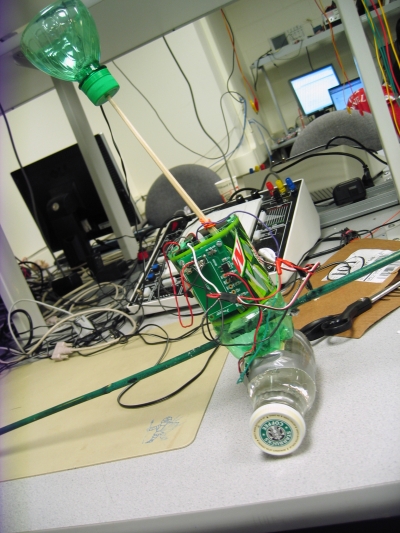
The tightrope walker was our inspiration for the design of the B2. As in the figure 1, the B2 has a stabilization stick, a balancing head for shifting its center of gravity and an MCU with accelerometer input for equilibrioception.
In designing the B2 we decided that we would utilize a very cost-efficient design in lieu of any expensive parts that might offset our budget. Because of this decision we ended up sticking with one MMA1260D that was sampled from Freescale. This accelerometer lacks high precision or accuracy, and made the programming process more difficult.
The best option for a robot of this design would be a gyroscope, but they are expensive and would make reproducing this robot quite pricey. With the accelerometer we were able to get quick output with very little conversion or set up. In the design phase these also helped because we accidently reverse charged one and blew it out. Replacing the accelerometer was very quick.
With the software we tried to avoid using too much complex math as it would slow down the reaction time between the MCU and the servo. Thus, we were not able to use any complex equations in our code design, though we did implement a PID controller.
Our design was not based on any standards and thus might not adhere strictly to any IEEE, ISO, ANSI, DIN, or other standards.
One big invention comes to mind when thinking of balancing, and that is the Segway PT. However, this product utilizes computers, tilt sensors and gyroscopes instead of accelerometers and microcontrollers. Thus, it is very different in design to the B2.
We decided to tackle the challenge of balancing using PID control, a control feedback mechanism used for systems that need to self correct errors. In our case, our error is any acceleration. Since the axis of our accelerometer is parallel to the ground when balanced. If the robot is tilted, gravity will register as acceleration. Our accelerometer does read acceleration do to the movement of the robot balancing head, however correcting this acceleration will keep the robot from moving too wildly. Consider the following PID equation:
In our case, PID is the amount of swing the robot will move his balancing *head to fix the error. What each term does is as follows:
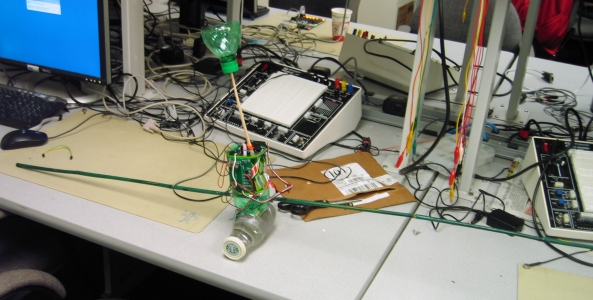
In terms of hardware we decided to keep the parts to a minimum and utilize recycled materials as much as possible. The main components of the B2 consist of the MCU and evaluation board, accelerometer, servo motor and two 9V batteries with voltage regulators. The chassis is made of a Mountain Dew (though we are not being sponsored in any way by Pepsi Co) bottle and the head consists of a chopstick with the top third of the bottle mounted to the top. The bottom of the chassis is stabilized by wide popsicle sticks. Refer to the parts list for details.
The body of the B2 is assembled with the servo mounted to the top back of the body, the MCU board on the inside left middle wall, one 9V battery underneath the servo, one 9V battery on a regulator board on the front outside middle wall and the accelerometer mounted to the rotational object below the B2 (in this case a glass Frappuccino bottle). This can be seen in the pictures of the B2. Because of accuracy issues that came from acceleration other than gravity we deemed it best to move the accelerometer to the base of the B2 instead of on the main body.
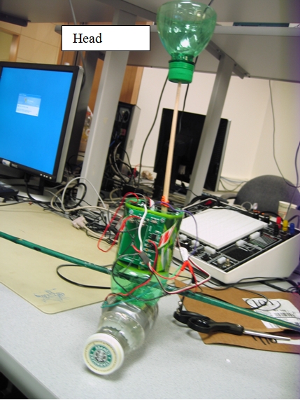
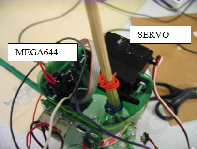
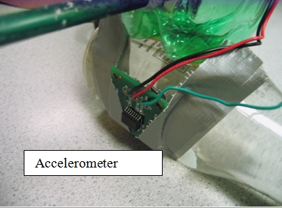
Figure1. Balance Bot (B2)
Our original plan for keeping equilibrium was to have a horizontal beam that would shift from side to side to adjust for weight, but for ease of setup we went with a moving head design instead. The head of the B2 extends about a foot off the body and is attached via the servo motor. The top of the head is open to allow for weights to be added or removed easily during the calibration process. The head swings with the servo, and therefore must be light enough for the servo to move at all times.
One 9V battery is attached to a Freescale voltage regulator board that allows for the 9V battery to be split into 3V and 5V outputs. We use the 5V output to drive the accelerometer. This 9V battery is also connected directly to the MCU board to power the MCU with 9V. The other 9V battery is attached to a LM340 5V voltage regulator that drives the servo.
The accelerometer is attached to Port A0 on the MCU and the servo output comes from Port C0. All of the grounds for each element in the B2 are tied together to form a common ground.
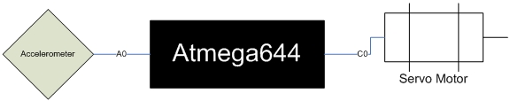
Figure 2. Block diagram of circuitry
At first all the parts were mounted to a soda can, but the coating on the can scraped off at the solder points for the various components causing them to short. Thus we switched to a larger and more durable plastic bottle.
The B2 uses only one input to determine how much correction it should do. This input is from the ADC from Port A0. The ADC is initialized as follows:
ADMUX = (0<<REFS1)|(1<<REFS0)|(1<<ADLAR);
ADCSRA = (1<<ADEN) | (1<<ADSC)+ 7
By default ADMUX selects channel 0 if no channel is specified in the ADMUX register. Setting REFS1 to 0 and REFS0 to 1 turns on the 5V internal referencing, and setting ADLAR to 1 tells the MCU to use only the top 8 bits for readings as the lower 2 bits are inaccurate.
The ADCSRA register controls the state of the ADC. Setting ADEN to 1 turns on the ADC, and setting ADSC to 1 starts the first conversion. When the conversion is complete ADSC becomes 0 again. Therefore in task2 we perform the operation ADCSRA |= (1<<ADSC) to start new conversions.
Adding 7 to ADCSRA sets the prescalar to 128 which means the frequency is divided by 128. We chose this frequency because it does slower conversions, thus increasing accuracy, while still sampling faster than task2 checks for new values from the accelerometer.
The converted value is stored in the ADCH register, which we store in Ain. The first conversion done is a dummy because the first conversion does not give a meaningful result. We then take the first true conversion and define the �center� of the B2 as this value. Thus, resetting the B2 allows the user to define a new center each time. This comes in useful when the user wants the B2 to balance at a position not in the direct center.
The timing for task1 controls the position of the servo. Task1 simply acts as a clock that outputs at Port C0�servoOut will run high then low then high and so on. This task runs according to the TIMER0 ISR which controlled by the following timing:
TCCR0B= 2;
OCR0A = 20;
TCCR0A= (1<<WGM01) ;
Setting TCCR0B to 2 sets the prescalar to 8, OCR0A to 20 tells the ISR to count 20 ticks and TCCR0A controls the clear on match. Thus, the timing becomes 16MHz/8*20 = 10�s.
Since the servo moves according to the length of the high signal sent to it (between 100 and 200 ms), there is a precision of 100 different positions for the servo according to the timing for the ISR.
Though the length of the low signal to the servo didn�t have to change, it was much easier and efficient, code wise, to just exclusive-or the output to Port C0 instead of changing the timing only for the high outputs.
Task2 is entirely responsible for the robot reaction. From the accelerometer read, the robot will decide where to adjust its head. Remember that adjusting the servo motor�s pulse width t1 is essentially adjusting the head.
First, the robot gets an ADC read of the accelerometer. Also, it immediately starts a new conversion for the next iteration of task2.
//get the sample
Ain = ADCH;
Ain= Ain;
//start new conversion
ADCSRA |= (1<<ADSC) ;
It turns out that the vibrations of the robot create a very noisy read of the accelerometer. So we decided to digitally low pass filter Ain. One of the simplest low pass filters is as such: 1. Keep track of the last 31 Ain values. 2. Take the average of all of the values and the current Ain. 3. Prepping for the next iteration, pop off the oldest Ain value and add the current Ain as the most recent value.
The above low pass filtering of Ain is as follows:
//Digital LOW PASS FILTER Ain
if(++AinHistIndex>31){AinHistIndex=0;} //cycle each element
AinTotal+=-AinHist[AinHistIndex]+Ain; //subtract FIFO value and add new Ain from total
AinHist[AinHistIndex] = Ain; //replace last Ain with new Ain
AinLP=AinTotal>>5; //compute Low pass filtered Ain
Note that AinTotal is optional. The average of all the elements in the Ain History (AinHist) could have been calculated as adding each element in AinHist and dividing it by 32. However, we opted to minimize 32 additions since adding the middle 30 elements each time is redundant. We can keep track of the total with variable AinTotal and just use only 2 operations to subtract the oldest Ain value and add the newest Ain value. The low pass filtered Ain is stored in AinLP.
After low pass filtering the accelerometer read, the second part of task is to decide how to react to that read. As explained earlier, we used a PID algorithm to decide where to move the robot head. Remember the three terms of PID involves current error, the integral of errors over time, and the derivative of error. These three terms are computed as follows
//PID
int newerror=AinLP-center;
derivative=newerror-error;
error=newerror;
integral+=error;
One may note that dt is 7ms, however this is irrelevant since dt is a scaling factor and as part of our PID algorithm we will later re-scale the three terms with the A, B, and C coefficients either way. We might as well forget dt and have it absorbed by the ABC coefficients.
One caveat to the integral is that we do not want the integral to runaway out of practicality. There is a point in the PID where you can�t adjust for a large integral, and so we clipped the PID to a -2000 to 2000 range.
if(integral>2000) integral=2000;
else if(integral<-2000) integral=-2000;
The adjust to be made is the PID equation (concept explained earlier) is as follows
PID = .97*error+.0375*integral+10*derivative;
//clip PID
if(PID>100) PID=100;
else if(PID<-100) PID=-100;
Similar reasons to clipping the integral, we also clipped the PID control to within reason of how much the robot can adjust. In terms of servo control, we originally had t1=150+PID, where 150 is the center position of the servo. However, we decided to smooth out the adjustments by average the previous t1 and 150+PID as
t1 =(t1+ 150+PID)/2;
At the end of task2, the robot has sensed its acceleration and calculated where to move its head. The servo communication is described above which relies on the t1 pulse width that task2 calculates.
We tested our robot on a flat table to see if it could balance itself. In fact it does balance it self, however not as well as we hoped. At times the robot will over compensate if you tilt it and let its balancing stick hit the table, because this introduces a sudden acceleration and change of acceleration into the PID system. However, the robot does eventually settle after oscillating around and center itself. One of the major limitations is that there is a point when the tilt of the robot is too much to overcome. The stabilizing stick does prevent the robot from tilting over too much, however we were unable to showcase the robot on a raised platform and increasing the range of swing the robot can tilt. We can conclude that the servo control was responsive to our PID control and the accelerometer and ADC conversion were good enough to balance in particular conditions.
We also tested the limits of the robot by putting the robot out of balance by adding a weight on side of the stabilizing stick and let the robot adjust. With the weight on either side (given that the head of the robot was heavy enough to pull that weight), the robot was able to adjust its head to counter balance the weight successfully.
In terms of danger, the moving head has hit us a few times in the face. However, the head is made of a plastic soda bottle and is innocuous. The stabilizing stick is very long but does not move hard enough to cause harm. Plus, the lab benches were just long enough to keep our robot from interfering with other benches with its long stabilizing stick.
As mentioned in the results, are robot only could balance in limited conditions. One of the major limitations was the sensing of balance. Using a single accelerometer is not the best way to do this. One of the huge complications of just using a single accelerometer is that there is a lot of acceleration due to the movement of the head. On top of that the Freescale accelerometers we used are notoriously not the best accelerometers for accuracy of fine acceleration changes. When we tried to use a second accelerometer to sense the axis perpendicular to the ground when the robot is balanced, it was practically useless to distinguish different acceleration between small angles of tilting. In the future, we would try to use a gyroscope to sense where balance is. The disadvantage is that they are pretty expensive (the ones we looked at were $70-80 range).
Another thing we would change is that body of our robot. Although cheap, the plastic bottle was very flexible and vibrated a lot during operation. This pollutes the accelerometer readings and complicated balancing. In the future, we would use a more solid body.
However, despite the above complications, the PID algorithm seemed to work and we recommend using it for any control system that has to adjust error. We thank Professor Bruce Land and Wikipedia for introducing the concept to us (look under background in appendix).
We do not seek any ownership of intellectual property of the robot. We however encourage hobbyists to take our project and improve it.
We followed IEEE code of ethics Ethical. Our robot does not pose a threat to harm an adult. However, we advise to keep children away from being hit from the balancing head. Our project is not proprietary and does not infringe upon anyone else�s intellectual property. We aimed to provide the full results of our project and hope you find our results useful for future endeavors. We accepted no bribes in our project, but were willing to sample parts from companies. We hope that our project showcases the ability of microcontrollers to control a dynamic system of balancing and stabilization. We implement this project from our own creativity but based off of the founded concept of PID. We seeked and accepted advice on our project; we thank Professor Professor Bruce Land in suggesting us to use a PID algorithm to balance. We treated all persons alike with no discrimination. In no way have we endangered anyone with out robot. We are open to help anyone interested in improving our project or any other project and encourage following the IEEE code of ethics.
We do not have any legal considerations in terms of regulation. However, we do advise not to let children get near the robot.\
| Part | (Brand) | Vendor Cost | |
|---|---|---|---|
| Mega 644 Microcontroller | Sampled from Atmel Representative | $0.00 | |
| Custom PC Board | Bruce | $4.00 | |
| DIP socket | Bruce | $0.50 | |
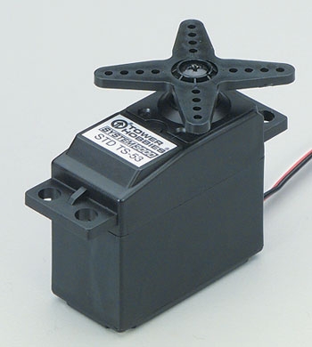
| Std Servo Motor (Tower Hobbies TS-53) | Bought from a friend | $9.99 | |
| Accelerometer (MMA1260D) | Sampled from Freescale acquired from Bruce | $0.00 | |
| 2 batteries (9V) | Dollar Store | $1.00 | |
| Soda Bottle (Mountain Dew) | Recycled | $0.00 | |
| Chopstick | Matin Caf� | $0.00 | |
| 3 Pennies | Change jar | $0.03 | |
| Bamboo Stick | Dollar Store | $0.15 | |
| Popsicle Sticks | Matin Caf� | $0.00 | |
| Starbucks Glass Bottle | Recycled | $0.00 | |
| 9V clip and regulator | Sampled from Freescale acquired from Bruce | $0.00 | |
| LM340LAZ-5.0 regulator | Bruce | $0.00 | |
| TOTAL | $15.72 |
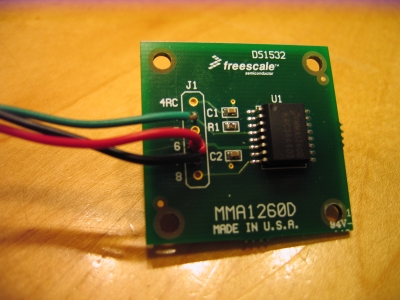
Freescale MMA1260D Accelerometer
Tower Hobbies TS-53 Standard Servo
#include <inttypes.h>
#include <avr/io.h>
#include <avr/interrupt.h>
#include <stdio.h>
//timeout values for each task
#define begin {
#define end }
// task subroutines
void task1(void); //flip pulse at C0
void task2(void); //calculate the position of the servo
void initialize(void); //initialize all components
volatile unsigned int time1; //timeout counter for task1
volatile unsigned int time2; //timeout counter for task2
volatile unsigned int t1=150; //pulse width (default 1.50 ms)
volatile unsigned int nextT1=150; //pulse width for next iteration
volatile unsigned int t2=700; //time period for each task 2 (7ms)
unsigned char servoOut; //Ouput value to servo
volatile char Ain ; //raw A to D number
volatile char AinHist[32] = {128,128,128,128,128,128,128,128,
128,128,128,128,128,128,128,128,
128,128,128,128,128,128,128,128,
128,128,128,128,128,128,128,128}; //Ain history for low pass filtering
volatile char AinHistIndex=1; //index to current element in AinHist
volatile unsigned int AinTotal=128*32; //total of Ain history
volatile char AinLP=128; //Low passed Ain
volatile char AinLast=128; //Last Low passed Ain
//PID
volatile int center=0; //center acceleration
volatile int error =0; //deviation from center
volatile int integral=0; //integral of errors
volatile int derivative=0; //derivative of errors
volatile int temp=0; //tempory variable buffer
volatile int PID=0; //PID control value
//**********************************************************
//timer 0 compare ISR
ISR (TIMER0_COMPA_vect)
begin
//Increment the time counters for tasks
++time1;
++time2;
end
void init_adc(void) { // function to initialize A to D converions
//init the A to D converter
//channel zero/ left adj /Internal 5v reference
ADMUX = (0<<REFS1)|(1<<REFS0)|(1<<ADLAR);
//enable ADC and set prescaler to 1/128*16MHz
//and clear interupt enable
//and start a conversion
ADCSRA = (1<<ADEN) | (1<<ADSC)+ 7;
//Dummy read (throw erronous first read)
Ain = ADCH;
Ain= Ain;
Ain;
ADCSRA |= (1<<ADSC) ;
//real conversion
while((ADCSRA<<ADSC)&1); //stall til read is ready
Ain = ADCH;
Ain= Ain;
center=Ain; //calibrate center acceleration
}
//**********************************************************
//Set it all up
void initialize(void)
begin
//initialize adc
init_adc();
//set up the servo
DDRC = (1<<PORTC0) ; // PORT C.0 is an ouput
//set up timer 0 for 10 uSec timebase
TIMSK0= (1<<OCIE0A); //turn on timer 0 cmp match ISR
TCCR0B= 2; //set prescalar to divide by 8
OCR0A = 20; //20 * 8 / 16Mhz = 10 us
TCCR0A= (1<<WGM01) ; // turn on clear-on-match
//init the servo status
servoOut=0x00;
//init the task timer
time1=t1;
time2=t2;
//crank up the ISRs
sei();
end
//**********************************************************
//Task 1
void task1(void)
begin
//toggle pulse to servo
servoOut = servoOut ^ 1 ;
PORTC = servoOut<<PORTC0 ;
end
//**********************************************************
//Task 2
void task2(void)
begin
//get the sample
Ain = ADCH;
Ain= Ain;
//start new conversion
ADCSRA |= (1<<ADSC) ;
//Digital LOW PASS FILTER Ain
if(++AinHistIndex>31){AinHistIndex=0;} //cycle through each element
AinTotal+=-AinHist[AinHistIndex]+Ain; //subtract FIFO value and add new Ain from total
AinHist[AinHistIndex] = Ain; //replace last Ain with new Ain
AinLP=AinTotal>>5; //compute Low pass filtered Ain
//PID
int newerror=AinLP-center;
derivative= newerror-error;
error=newerror;
integral+=error;
if(integral>2000) integral=2000; //limit integral
else if(integral<-2000) integral=-2000;
PID = .97*error+.0375*integral+10*derivative;
//clip PID
if(PID>100) PID=100;
else if(PID<-100) PID=-100;
t1 =(t1+ 150+PID)/2; //compute new pulse width as avg of old t1 and (center position + PID)
//avg smoothes out transisiton
end
//**********************************************************
//Entry point and task scheduler loop
int main(void)
begin
initialize();
//main task scheduler loop
while(1)
begin
if (time1>=t1){time1=0; task1();}
if (time2>=t2){time2=0; task2();}
end
end