By: Guntawee Thipmanee and Marwan Sledge
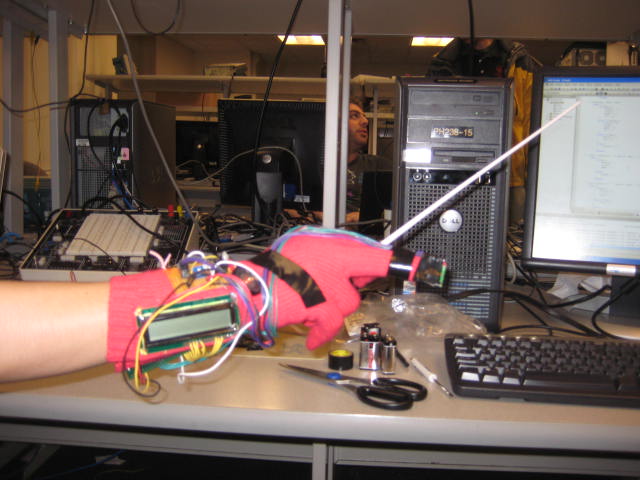
Figure 1: Der Kapellmeister in Action
Contents
This project is implemented with a glove, resembling a conducting baton that analyzes gestures and interprets them into musical elements.
Der Kapellmeister is a simple tool that tests a user's ability in basic conducting, using a real conducting baton. As a user performs a gesture, the tool will display the tempo, time signature, and beat number on the LCD screen, and output a tick sound through the speaker. The system can analyze up to four different time signatures. As a result, the practical features of this tool would be useful especially to beginners of conducting. Der Kapellmeister is a compact mobile set, consisting of a baton and a glove. An accelerometer is attached to the user's middle finger, and other hardware components such as the microcontroller, LCD, and speaker are stitched to the wrist area of the glove.
(BACK TO TOP)Conducting is a well respected art that has been around for centuries. The basic purpose of the conductor is to keep a steady pulse for the group of performers (that can range from a small ensemble to a large orchestra with choirs). The more advanced functions include cueing up the players and dictating articulation, dynamics, phrasing, etc. The highest level job of the conductor is to make music with the orchestra where the players are performing his or her interpretation of the material. At this level, the conductor has the artistic freedom to do what is necessary to bring out the best performance possible according to his or her tastes.
Back to the basic technical function of keeping a steady tempo. This is done most of the time with the right hand either with or without a baton. The conductor is responsible for gesturing the exact start of every beat (and measure) by using a single point for each beat as a reference point. This is called the ictus. When the conductor passes or stops at an ictus point, the beat has started.
Here are the most basic gestures:
Commonly used time signatures are 4/4, 2/2, 2/4, 3/4, 3/2, and 1/1 (often used for fast tempos). Note that 2/4 and 2/2 can be notated with the same gestures since both have only 2 beats per measure. Likewise with 3/4 and 3/2. Less common ones are 5/4, 7/4, 6/8, 3/8, 12/8, and 9/8 where these are considered compound signatures as they can be broken up into a combination of the simpler signatures mentioned above.
Our goal was to be able to use the device to conduct the Recapitulation of the A theme, the climax, and the resolution from the first movement of the Piano Concerto No. 3 in D minor by Sergei Rachmaninoff (~3.5 mins). This portion has a nice mix of 2/2, 4/4, and 3/2 time signatures.
(BACK TO TOP)In all honesty, it took us a long time to decide on our final project. Perhaps, one reason is that we were overwhelmed with numerous possible projects that exist in so many areas, and none of them struck us particularly. Nevertheless, we wanted to pick something that is not only interesting but also practical. Due to the short amount of time to do this project and the abundance of new information that we needed to learn, we set a realistic goal by selecting something that is simple, yet meaningful. Since Marwan is a passionate musician, he suggested that we do something musical related. Consequently, our first idea was a simple "Piano Hero", a game similar to the Guitar Hero that simulates playing of the piano, using ten accelerometers as sensors attached to all fingers; however, it turned out that having so many accelerometers would be costly, and technically difficult. In addition, taking care of little details of the piano such as the difference between the white and black keys, seemed to be impractical with our setup. For these reasons, we decided to give up on this idea, and go with our "Conductor Hero" idea instead. We call it "Der Kapellmeister", the German word for conductor. It turned out to be a good choice since it only needs one accelerometer and was simple enough for our current system setup.
The design process was done in many stages. First, we focused on building and testing all the hardware components. We put together several components, such as the Atmel Mega 644 MCU, an LED, a power outlet, and a crystal oscillator on the proto board. Next, we tested other components that we purchased; the LCD and the accelerometer. To test and program our MCU, we used several tools like STK500 board, hyperterm, LEDs, oscilloscope, and multimeter to make sure that everything was fully functional. After getting all the hardware components functioning, we integrated them together with the baton and glove.
The following is the overview architecture of our project:
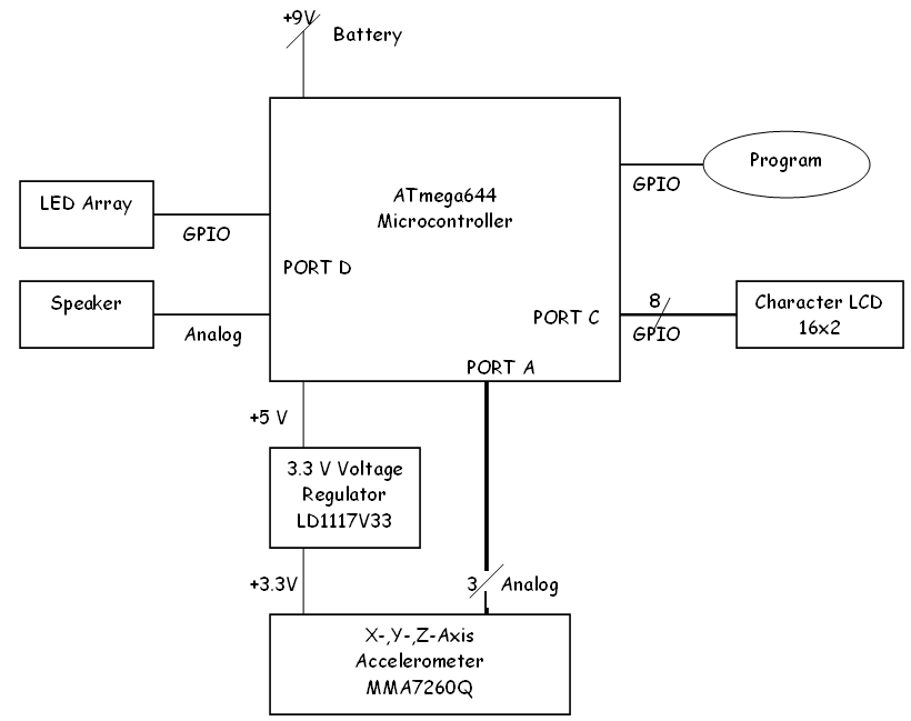
Figure 2: High Level Architecture
The accelerometer produces voltage signals that are sent to the analog to digital converter through port A of the MCU. After computations have been completed in the software, the outputs will be sent to the LCD as visual display, and the speaker as sound. The MCU is programmed through the flash memory via the STK500. A LED Array is used for testing purposes.
In the microcontroller, our software portion is executed. The acceleration values from the accelerometer are sent to the MCU. They undergo several parts of analyzing steps; and finally, the outputs in term of time signature, beat, and tempo will be display on the LCD and the speaker. Following shows a flow diagram of the software portion of the project:
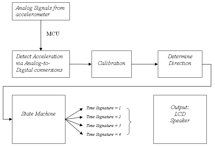
Figure 3: Software High Level
The main tradeoff comes from our overall hardware design, due to the fact that we want our system to be small, simple, user-friendly, and mobile. We have an option of using an AVR STK500 board which has several hardware components and hyperterm as our output; however, it turned out that we do not need many features from the STK500 and the board itself can be quite costly. An alternative to outputting through the hyperterm is to use an LCD, which we have used several times before in our previous labs. Similarly, the power supply from the power adapter that feeds the microcontroller can be replaced by a 9-volt battery. Nevertheless, the tradeoff was that we had to make our own custom board, which is a difficult process, especially the soldering part. Putting together a mobile set is also a challenging task. We need to stitch all the hardware components onto a glove; thus, the sewing needs to be done carefully and the glove needs to be sturdy for the safety of the product.
Another tradeoff is the choice of our accelerometer. Since our project requires a high accuracy of fast movement detection, a high sensitivity accelerometer is needed. The accelerometer in the lab only gives sensitivity of 1.5g which might not be good enough, even though it is a sample and thus free of charge. We also needed to pick between a digital accelerometer and an analog accelerometer. The analog one is easy to implement as it does not require any communication protocol. On the other hand, the digital accelerometer has sophisticated communication interface such as SPI or I2C. In addition, the digital accelerometer has an internal ADC, so we do not have to worry about the analog-to-digital conversion part. Learning to use SPI or I2C would required time because we had never implemented them in the previous labs. Finally, making a surface mount for the accelerometer became a concern as well. Most accelerometers that we consider come in special packages and are very difficult to solder into a proper interface. The option of buying the pre-soldered accelerometer on a breakout board is significant but also costly. Nevertheless, after calculating our estimated costs, we decided on the selectable-sensitivity, analog accelerometer presoldered on a breakout board for our final implementation of the project.
There are no standards associated with this project, especially since we did not use SPI in the final implementation of the project.
There are no patents of copyrights associated with this project.
(BACK TO TOP)We use a custom PC board, which is designed by the ECE 476 Prof. Bruce Land, for the Atmel Mega644 MCU. It includes a power supply, crystal oscillator, LED, Jumper RS232 interface and bypass capacitors. There is a six-pin header which allows flash memory programming from an STK500.
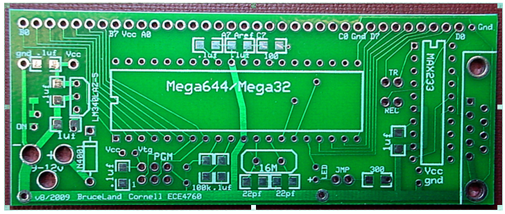 Figure 4: Prototype Board for Atmel Mega644
As we place emphasis on the mobile feature of our application, we decide to use a 9-volt battery the central power supply for the MCU and all other components. The jumper is connected so that the MCU could be programmed from the STK500. For maximum computation speed, the 20-Mhz crystal clock is used instead of the usual 16-Mhz.
A good accelerometer is essential for this project in order to keep track of movement of the baton. We use one from Freescale, a 3-axis sensitivity-selectable analog accelerometer (MMA7260Q). With a 3-axis accelerometer, the baton�s acceleration can be measured in every direction. This chip is purchased from Sparksfun Electronics; it has been pre-soldered and comes together with a breakout board, which is convenient for us. We need a high sensitivity for this project, so we select 6g as our choice.
The MMA7260Q is a low power device that operates on 2.2 V to 3.6 V power supply, and uses little current. We have a 3.3V voltage regulator to maintain the voltage supply. It has three analog outputs: X, Y, and Z axis. Acceleration on each axis generates a voltage from .25V to approximately 3.1V (Vss + .25V to Vdd - .25 respectively). When there is no acceleration, the output for a given axis is roughly at the midpoint of the voltage range. Our sensitivities can range from 200 to 600 mV/g, depending on the sensitivity chosen.
The accelerometer's sensitivity can be selected by 2 of the pins, GS1 - G-select 1 and GS2 - G-select 2. Following shows the four different choices of sensitivities and their connections.
The four types of sensitivity have different characteristics. For example, the 1.5g sensitivity would have a range of -1.5g to 1.5g, while the 6g sensitivity has a range of -6g to 6g. The low-g has high sensitivity, but since it is so sensitive, it also has a high range of error. On the other hand, the high-g has lower sensitivity; however, the error range is small. The following shows the sensitivity characteristics of the accelerometer.
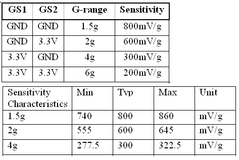 Figure 5: Sensitivity Characteristics
We decided to allow the sensitivity to be selectable by allowing the user to wire the desired sensitivity through the ground and 3.3V pins in the custom board. A high g feature would allow us to distinguish among different types of motion, which dictate the tempo. Finally, the values of the accelerometer would need to undergo analog-to-digital conversions by the ADC function of the MCU, and thus, the signals from the accelerometer would be sent to PORT A of the Mega644.
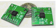 Figure 6: Triple Axis Accelerometer Breakout - MMA7260Q
 One challenge was to have an appropriate supply voltage for our accelerometer, which needs 3.3 V. We use a 9-V battery to supply the voltage for the protoboard; subsequently, the MCU has a 5V voltage regulator which maintains this voltage for all of its pins. To get a steady 3.3V for our accelerometer, we decide to use a 3.3V voltage regulator, LD1117V33 from ST. To use it in our application, two capacitors need to be connected as well. The circuit below shows the connection:
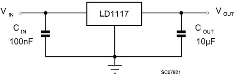 Figure 7: Voltage Regulator Circuit
The Voltage regulator circuit, LCD contrast potentiometer, and sensitivity select pins were soldered to a small PCB board for convenience. This was also sewn onto the glove.
We use the 16x1 alphanumeric LCD, MDLS16264, similar to the units normally used in previous labs. It has an interface created by Scienceprog.com, and it is connected to PORTC of the MCU. Following shows the connection of the pins of the LCD to the MCU.
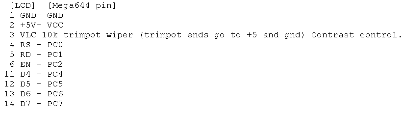 Figure 8: LCD Setup
A mini 8-Ohm speaker is used for the sound output of the ictus tick. It is connected to pin D.0 of the MCU.
During a conducting session, the hand and the baton are together in the same motion. Therefore, all of our hardware components are sewn onto the glove.
The accelerometer is placed on the middle finger with wires connecting to the MCU. The MCU, LCD, speaker, and battery clip are all stitched onto a long glove which a user would wear. The battery slides directly into the battery clip, making it easy to change the battery. The LCD is sewn on the wrist like a watch, so the user can easily read off the results of his/her conducting.
(BACK TO TOP)The software part of this project mainly consists of detecting the acceleration values from the accelerometer in all three directions, then analyze these values to interpret them in terms of musical gestures. To distinguish among different gestures, a state machine was used. Timing is also critical in this case, so the interrupt service routine (ISR) is utilized.
A tricky part of the software design was to determine the direction the user is going, as well as time interval for certain movement. Obviously, fast movement yields high tempo, and vice versa. From the oscilloscope, we determined that certain motion of the hand (up, down, left, or right) is approximately less than 400msec. Therefore, we setup a timed while loop that polls as many samples as it can within a 400 ms interval. Within in this period, we only store the most positive and most negative values and the time at which they occurred. Since each motion has a positive peak, as well as a corresponding negative peak (acceleration and deceleration), we snapshot both peaks as well as the time that they occurred. We can then determine which direction the user is going by checking which peak came first. For instance, if a large positive spike in the Z axis happened before a large negative Z acceleration, then the user most likely moved in an upward direction before coming to a stop.
We use timer0 to run the time ISR. We set the TCCR0B register to a divide by 8, set the compare match to 250, and set a div variable by 10 to produce a 1 millisecond increment (20,000,000 / 8 / 250 / 10 = 1000).
After the outputs in X, Y, and Z axis of the accelerometer are inserted into the MCU, an analog-to-digital conversion needs to be done. The ATmega644 has an ADC feature that can produce a digital value from the analog signal inserted into Port A. The ADC produces 10-bit resolution samples at a rate of 150,000 samples per second. The ADC is connected to an 8-channel multiplexer which allows 8 different single-ended voltage inputs (referenced to MCU GND) conversions. In our project, we need three values of ADC, and we use pin 0, 1, and 2 for the X, Y, and Z axis respectively. In this ADC process, a voltage reference also needs to be set. We decide to do this by externally setting the AREF pin. Since our accelerometer output range is from 0 to Vdd (3.3 V), we set AREF pin on the custom board directly to Vdd.
To initialize the ADC, we turn on the ADLAR bit in the ADMUX register, which make the result of the ADC left adjusted for the future outputs. Also, in the control register ADCSRA, the enable bit (ADEN), the start conversion bit (ADSC) are turned on. The first 3 bits of ADCSRA are the prescalar select bits; these are set to 7, so that the division factor 128. In other words, the ADC clock becomes 1/128*20MHZ.
Next, to detect acceleration in each axis, the ADMUX must be changed. Specifically for each axis, the ADLAR bit is turned on, and the selection bits are: 0 for X axis, 1 for Y axis, and 2 for Z axis. Then, to get the sample and start conversion, the ADSC bit in the control register is turned on. Bits 7 through 4 of the ADCSRA register must be on before we read the output values. The 10-bit output comes from the registers ADCL and ADCH. In this MCU specifically, the ADCL needs to be read before ADCH.
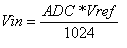
Vref in our case is (Vdd-0.25 � GND+0.25), which is around 3.05V. Next, to convert this voltage in term of g unit, depending on the sensitivity selected, divide by the output value of the corresponding sensitivity (in the unit of V/g). For example, at 6g the output is at 200mV/g, the equation becomes:

If we use 6g sensitivity, our output is now in the range of 0 to 12g. Thus we subtract this result by 6 to get the range from -6g to 6g.
We use the acc() to do this process for all three axis.
A function tick() is called. This is simply produced by switching pin D.0 on and off rapidlys for a small period of time.
As usual, we use the LCD library lcd_lib.c and lcd_lib.h from Scienceprog.com in order to display the LCD. The LCD setup is done calling LCDinit() to initialize the display, turn the cursor off using LCDcursorOFF(), and then clear the display by calling LCDclr(). After the display is cleared, it can then be written. Next, set the cursor to certain position of (X,Y) (where Y=0 refers to the first 8 characters and Y=1 for the last 8 characters on the sole 16 character line) by calling LCDGoToXY(). The writing part is done by calling sprintf and write to the LCD buffer. Then LCDString is called to display the contents of the LCD buffer to the screen. In this project, we write the values of the beat, tempo, and time signature. We use function disp() to do this task.
Since the position of the conducting hand does not always correspond to zero g (due to causes such as gravity, as well as initial position of the accelerometer), we need a system of calibration every time at the beginning of the conducting session. To zero out all of the initial noise in the system, we grab four samples for each axis consecutively, compute the average for each axis separately, and save those values as offsets. These offsets are subtracted off of any acceleration values computed thereafter.
This part determines the time signature and beat patterns. Each movement of the hand will deliver results in four directions (up, down, left, and right [each is a separate flag]) and their corresponding acceleration values. We compute Up, Down, Left, and Right by checking whether the current acceleration (within the 400 ms interval) is above a specified threshold.
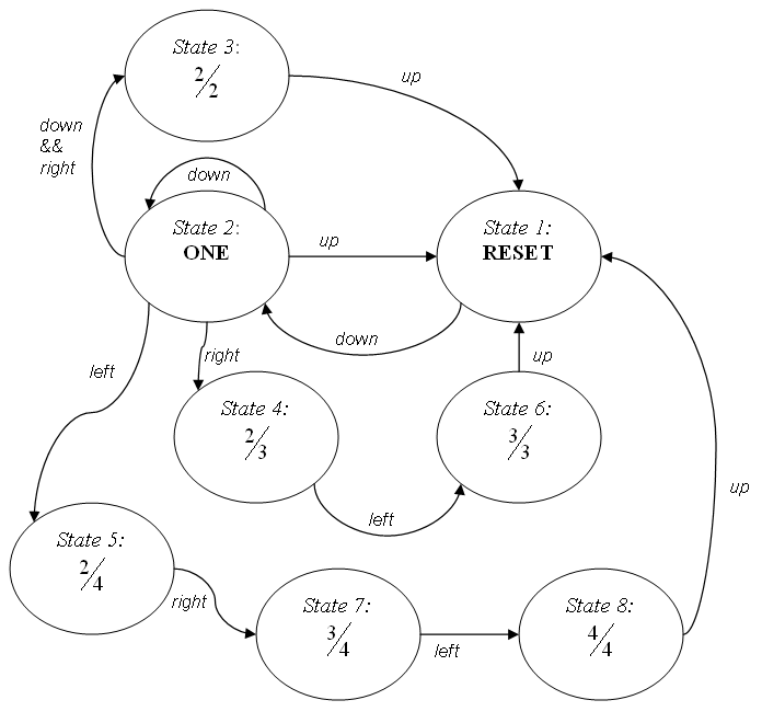
Figure 9: Software State Machine
There are four different time signatures in this state machine, which corresponds to 8 states. This is because each beat in a time signature corresponds to one state. The initial state is called RESET which starts or resets the system. To proceed to all other states, a down movement needs to occur, which changes the state to State-2. This is because all time signatures have the same initial movement, which is down. When the completion of each time signature arrives (specifically at State-2, State-3, State-6, and State-8), a user inserts a up movement in order to return to the initial state, RESET. The user can perform an upward motion at any time to initiate a reset; to start over or a new measure.
At State-2, aka ONE, different hand movements begin to branch out to different states. If a down movement is detected, it remains at state ONE. If down and right both occur, it proceeds to State-3, which measures time signature of 2. If right occurs, the state changes to State-4, which checks for time signature 3. Lastly, if left occurs, the state changes to State-5, which checks for time signature 4. If the user goes back up, then the time signature can be interpreted as 1, and will reset to a new measure.
If both down and right are detected in State one, then the system goes to state 3; a time signature 2 has detected. At State-4, if left occurs, the states changes to State-6. And if this is followed by up, then time signature 3 is detected and the states moves to RESET. Likewise, at State-5, if right is detected (moves to State-7), follows by left (to State-8), and by up (to RESET), the time signature 4 is detected. This combination maps out the actual gestures for the four time signatures quite well.
We use the function tem() to calculate the tempo (in beats per minute) at the end of every measure using the following equation: (time signature; number of beats per measure) * 60,000 milliseconds per minute / time duration of one measure.
(BACK TO TOP)As it turns out, we have ample time to perform our calculations and gather samples. We chose to use a 20 MHz crystal so that we can execute as many instructions as possible per millisecond timeframe.
Initially, we thought of computing the velocity values by integrating the acceleration over time, in order to get accurate results. However, such implementation proved to be challenging. The sampling rate of the ADC is not high enough to sample at all the acceleration values. As we look for when the acceleration values cross between positive and negative, the ADC sampling might skip that point due to the low sampling frequency. Even thought the ADC is advertised at 15,000 samples per second, we can only get about 40 samples per axis per 500 milliseconds (120 samples total). Consequently, we come up with an alternative way to find the peak, which is simply by comparing the current value with the stored previous values. We find that we are able to successfully detect which direction the user is going if the user is going at a sustainable speed. However, our timing is too off to accurately determine which gesture is being implemented and which state is the appropriate state. In retrospect, we should�ve used position sensors instead.
None of the parts require high voltage or high current, and there is no direct contact with any part of the body. Plus we use a 9V batter instead of a plug in power supply.
This device can be used for training conductors at the more technical side of the art. The user can practice keeping a steady tempo and be more precise in tempo. It is very analogous to using a metronome while practicing Hanon exercises on the piano.
(BACK TO TOP)This project fell far below expectations. It is very unreliable and unstable in terms of detecting the ictus points of the gestures. We've learned that accelerometers are not the best sensors for our application. And, we've learned the hard way that SPI isn't as easy as it looks.
One of the biggest difficulties was to differentiate between the downbeat of a 2 time signature and the downbeat for all the other time signatures. The reason is that the accelerometer often outputs multiple directions due to tilt and noise even though only one direction was intended. This can be fixed by adjusting the sensitivity, but it comes at a tradeoff since it will make it harder to detect when you want to detect those directions.
Also, since our project is not new or innovative or exciting in any way, there are no concerns or considerations for any intellectual property (publishing papers, patents, etc.), rendering our project worthless. Our project conforms to all standards and is rendered completely safe.
For the first few weeks that we worked on this project, we used a digital accelerometer from ST Microelectronics, which is a 3-axis and sensitivity-selectable that also comes in a breakout board. We thought that this accelerometer is convenient to use, because of its several useful features, including digital outputs, and Analog-to-Digital conversion. Nevertheless, the serial communication interface for this accelerometer presented a big challenge. We tried to use SPI as our communication interface; however, we were unable to get any output from the accelerometer at all. We checked several potential sources of error, including the code, timing, operating characteristics, necessary conditions of SPI in the Mega644 chip, etc. We had spent a lot of time trying to make this work; however, we were not successful. When the problems still persisted and the deadline was soon approaching, we decided to switch our accelerometer choice to the analog one that does not require sophisticated communication interface.
The software design for this project was built from scratch. Only bits and pieces of code used in previous labs are used. If our code resembles that of another project, it is completely accidental. I assert that I am the author of the code and the code is original for our application.
(BACK TO TOP)We, the members of the IEEE, in recognition of the importance of our technologies in affecting the quality of life throughout the world, and in accepting a personal obligation to our profession, its members and the communities we serve, do hereby commit ourselves to the highest ethical and professional conduct and agree:
1. to accept responsibility in making decisions consistent with the safety, health and welfare of the public, and to disclose promptly factors that might endanger the public or the environment;
2. to avoid real or perceived conflicts of interest whenever possible, and to disclose them to affected parties when they do exist;
3. to be honest and realistic in stating claims or estimates based on available data;
4. to reject bribery in all its forms;
5. to improve the understanding of technology, its appropriate application, and potential consequences;
6. to maintain and improve our technical competence and to undertake technological tasks for others only if qualified by training or experience, or after full disclosure of pertinent limitations;
7. to seek, accept, and offer honest criticism of technical work, to acknowledge and correct errors, and to credit properly the contributions of others;
8. to treat fairly all persons regardless of such factors as race, religion, gender, disability, age, or national origin;
9. to avoid injuring others, their property, reputation, or employment by false or malicious action;
10. to assist colleagues and co-workers in their professional development and to support them in following this code of ethics.
We made sure to follow the IEEE Code of Ethics throughout this project. We gave credits to all the references that we have made, such as the vendor sites and our instructor's tutorial pages. We have learned a lot from this project and gained further technical competence, especially in basic circuit design, creating custom board, serial communication interface, as well as the relationship between conducting and electronics. We would be willing to assist any colleagues who need the knowledge that we have obtained from this project, regardless of their races, religions, or genders. The developers of this tool are of different background: race and national origin. Nevertheless, both worked equally hard together to create this product. The developing team is open to criticism, because we believe that constructive criticism is a positive thing in which we would learn to make improvement. We welcome any feedback from our peers and users of this product about what they like and dislike, so that we would know what we can do to improve the product. We are honest in disclosing information, including our claims and estimations. We do not take bribery in any forms. We pay attention to the safety of our product. For example, even though we realize that our glove might not be the steadiest, we make sure all the component parts are sewn properly so that they would not fall off.
(BACK TO TOP)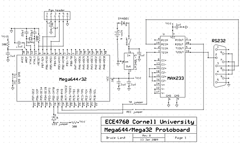
Figure 10: Prototype Board, Schematic
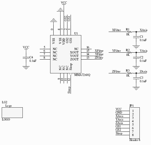
Figure 11: Analog Accelerometer, Schematic
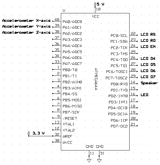
Figure 12: Overview of the connections to the Mega644
(BACK TO TOP)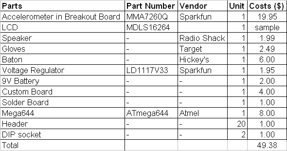
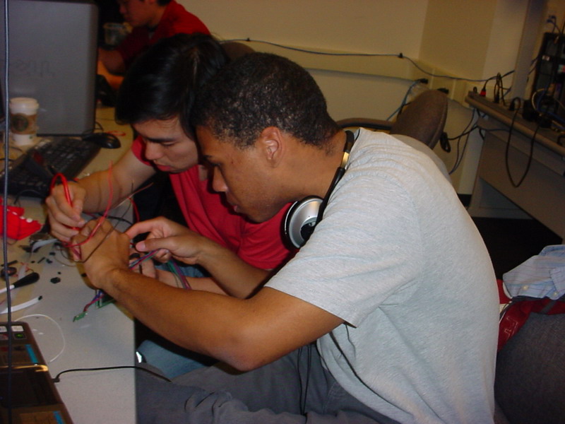
Figure 13: Marwan and Guntawee, working on the project
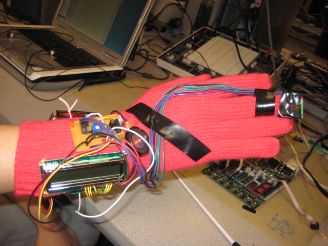
Figure 14: Der Kapellmeister, with view of the LCD, the speaker, and the voltage regulator circuit
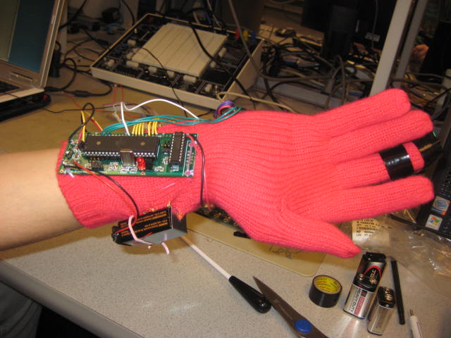
Figure 15: Der Kapellmeister, with view of the MCU and the battery
(BACK TO TOP)