"Recreating the experience of playing and learning an acoustic guitar electrically."
Joel Ong, Frank Chen, Justin Leow
Introduction
Our project recreates the experience of playing an acoustic guitar electrically using vibration sensors, push buttons and the Karplus-Strong algorithm.
Our basic idea is to model an acoustic guitar as closely as possible and then implement additional functions not available to the conventional guitar. This includes allowing the play of the guitar with sound being output to earphones, allowing for practice without disturbing others, as well as a chord-learning mechanism based on LED-signalled instructions and other functions.
A close modeling would mean that we use push buttons to simulate actual depressing of strings at specific fret locations, calibrate vibration sensors to detect strumming of guitar strings, and faithfully recreate a representation of the guitar body. For the production of guitar strumming sounds, we used the Karplus-Strong algorithm that synthesizes a plucked string sound signal.
High Level Design
Rationale/ Sources for Project Idea
Our final project idea originated from the initial idea of creating a self-playing automated guitar.
That idea was scrapped after some consideration due to the mechanical complexity and equipment involved, and hence we opted for a more electronic solution
to the idea of a project involving a guitar.
We decided to accurately model an acoustic guitar that would output sound signals based on the Karplus-Strong algorithm for the plucked string signal synthesis. The guitar should essentially be a recreation of the acoustic guitar, but with additional features that would otherwise be impossible in the conventional guitar. To accurately model an acoustic guitar, we would require a somewhat realistic simulation of fretting and plucking of the strings, as well as to create a semblance of the acoustic guitar body. The Karplus-Strong algorithm produced sound should also resemble closely the sound of the actual acoustic guitar. Also, we required our final product to be portable and not too heavy, which would then influence the design and electrical components of our final guitar.
In terms of additional features, we first decided that the sound could be output to speakers or to earphones, to allow the option of silent practice sessions that would not of nuisance to others. Also, we decided to implement a fret-position signaling system which would allow amateur players to learn chord positions quickly and be able to familiarize themselves with songs written with guitar tabs efficiently. In a sense, one could be adding tabs of new songs they want to play whilst connected to the computer and then unplug and be able to freely play chords from one particular song.
Background Math
The Karplus-Strong Algorithm was developed by Kevin Karplus and Alex Strong in 1978 and consists of a high-order digital filter representing the string as well
as a short noise burst, corresponding to x(n) that is initialized in the delay-line, which represents the plucked excitation. This is represented in the figure
shown below.
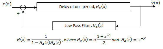
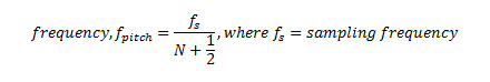
H_a(z) is a low pass filter, and alpha corresponds to a loss factor which essentially determines the decay time of the tone, and has to be less than 1 for filter stability. H_b(z) represents a delay line, whose length N determines the pitch frequency of the tone. By simple calculations, we can obtain the loop length of the entire system to be N + 1/2 samples. Since the low pass filter is constantly changing the contents of the loop, the output signal is only close to periodic. Nevertheless, using the term loosely, we can easily see that the period of the output signal would be the effective loop length.
Logical Structure
Below is the block diagram of the system wiring for our acoustic guitar.
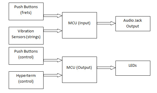
The MCU (input) interfaces with the vibration sensors to determine when to generate a corresponding sound signal, and then uses the input from the push buttons to determine the exact pitch frequency to be played, before outputting the sound signal at the audio jack. The MCU (output) interfaces with control push buttons [start/pause/stop] as well as hyperterm controls to output the relevant LED signals for proper fret position signalling.
Hardware/Software Tradeoffs
The Karplus-Strong algorithm was implemented in software for the six separate guitar strings instead of using hardware since we wanted a more flexible control of the loop
filter as well as the delay line, which would be difficult to implement in hardware. The tradeoff in software would be a relatively slower processing, which we tackled
using a 20MHz clock as well as code modifications described in later sections.
A low pass filter was implemented in hardware to smoothen the sound output from the MCU since it was a much easier alternative.
Instead of using multiplexers and significantly more complex code to attempt to reduce the number of ports required for both software and hardware, we decided to use separate MCUs for the input (push buttons and vibration sensors) and output (LEDs and other controls) circuits. This, though increasing the hardware cost, would reduce the complexity of the software and corresponding processing time, which could be devoted to the Karplus-Strong algorithm iterations instead. Also, the cost of the multiplexers and wiring configurations contributed to our decision of having two MCUs.
Standards and Intellectual Property
The relevant standard we adhered to was ISO 16:1975 that specifies the frequency for note A in the treble stave to be 440Hz. Tuning and retuning have to be effected by
instruments producing it within an accuracy of 0.5Hz.
With regards to patents and copyrights, we considered the patents regarding the Karplus-Strong algorithm as well as other possible electronic acoustic guitar models. To our best knowledge, most electronic acoustic guitar models mainly incorporate a pickup which allows for amplification of the acoustic guitar tones but otherwise, there have been no actual commercial guitars models utilizing the Karplus-Strong algorithm to produce sound. Regarding the patents in the Karplus-Strong algorithm, we refer to Wavetable Modification Instrument and Method for Generating Musical Sound (US4,649,783), as well as Independently controlled wavetable-modification instrument and method for generating musical sound (US4,622,877). These patents have expired.
Hardware Design
Mechanical Construction
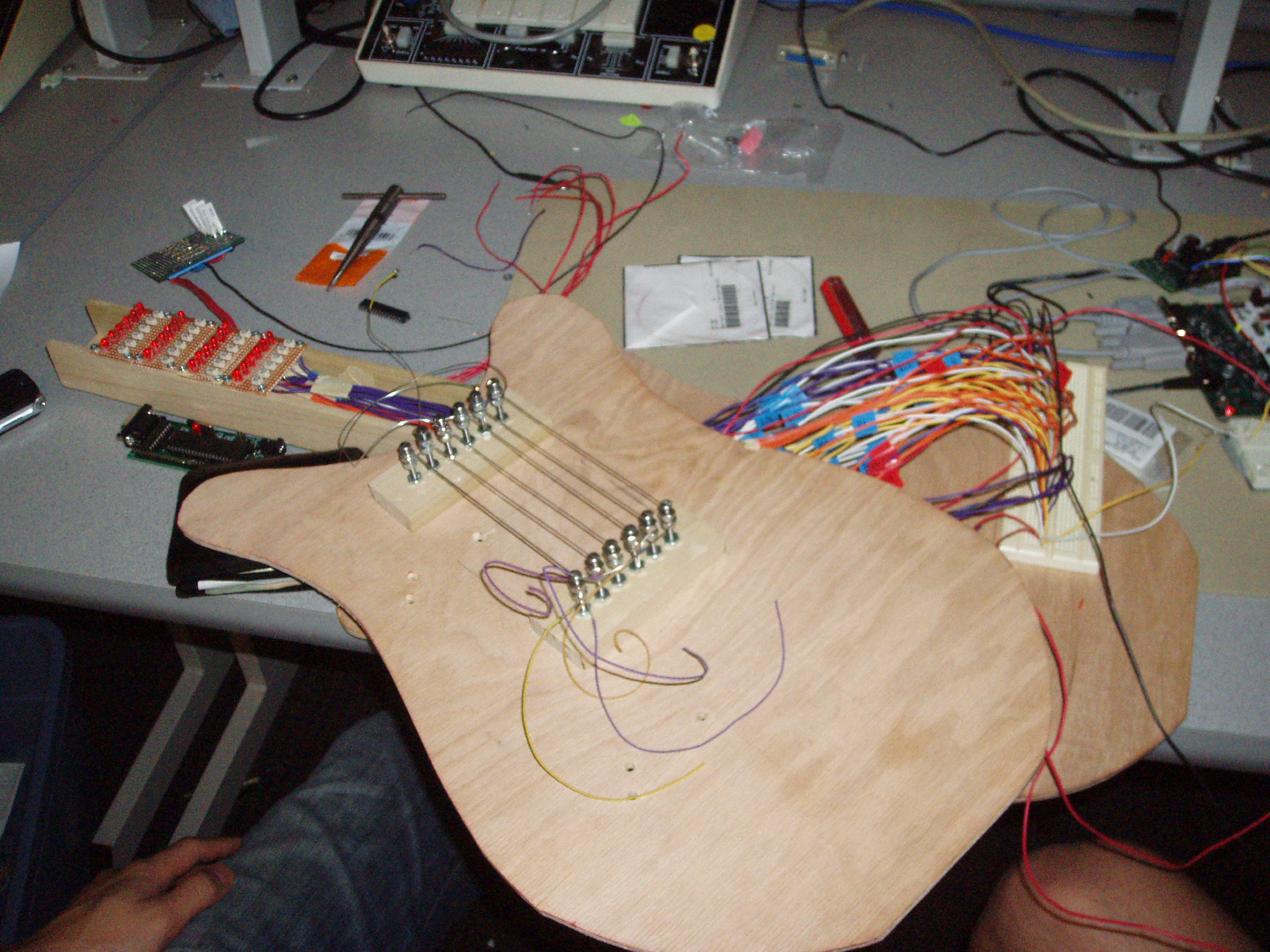
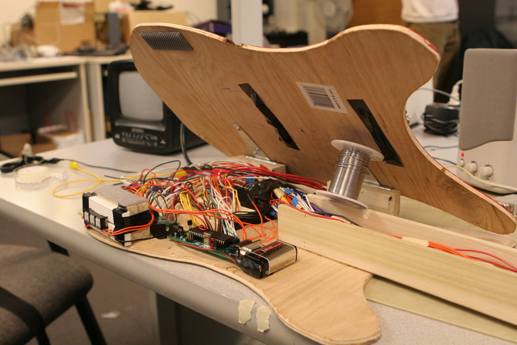
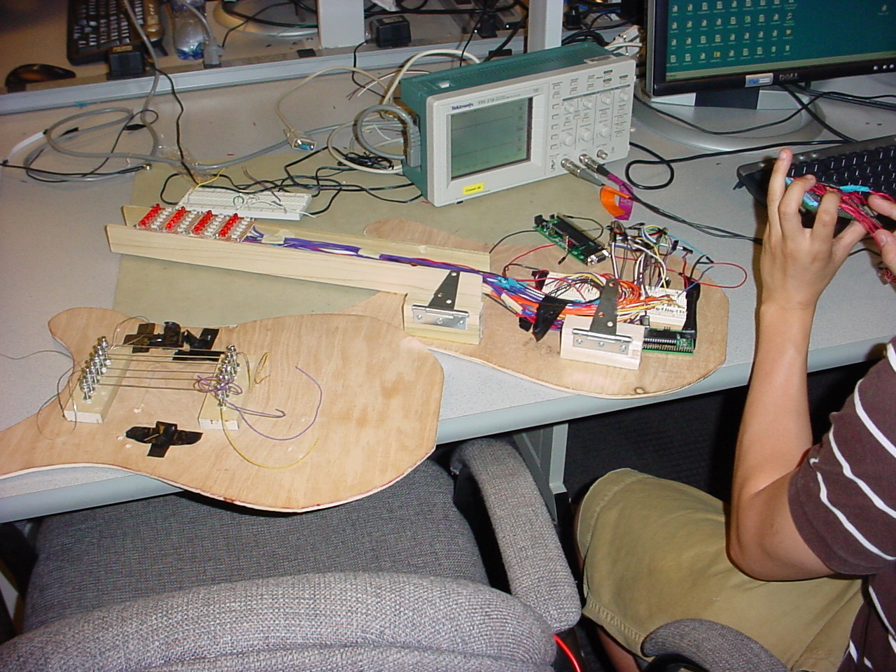
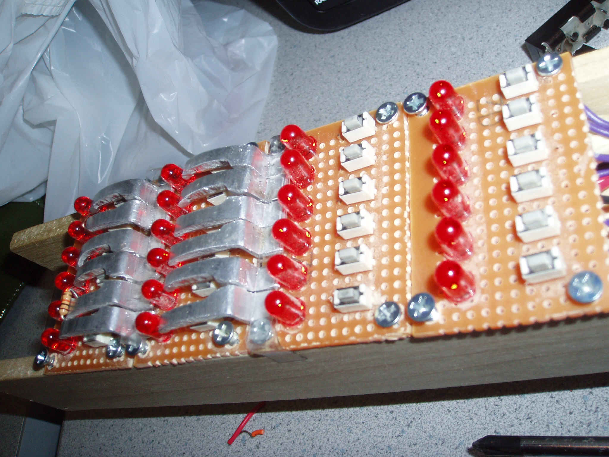
To accurately model the acoustic guitar, we used wood to carve out a neck and a top/bottom panel of the guitar body whereby the electrical components would lie in between
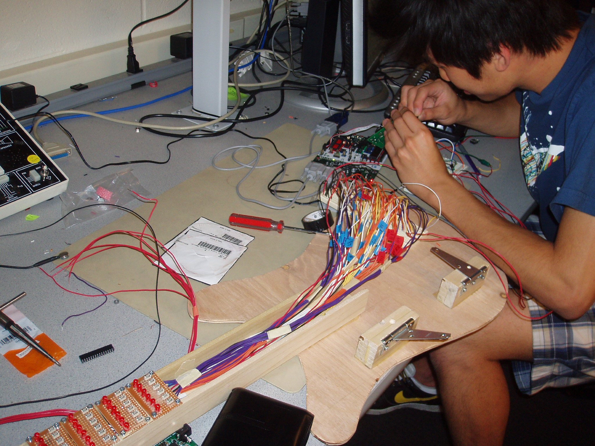
the panels. The proportions of the neck closely adhered to what a conventional guitar neck would be, and on it we put 4 solder boards each with a row of 6 LEDs and 6 push buttons
to simulate the fret positions of the guitar. Similarly, the proportions between each string was taken from an actual guitar and the push buttons were spaced based on the
proportions.
Fretting
To simulate the sensation of depression of strings during fretting, we decided to use 24 pushbuttons (Digikey, P13588S-ND) to simulate 4 possible fret positions for 6 strings.
Our decision to only simulate the top 4 frets was due to a constraint of I/O ports to the MCU and also with the consideration that most classical chords could be played using
just the top 4 fret positions. The circuit of the push buttons is simple, mainly consisting of a switch in series with a 10K resistor that connected Vcc to GND. The resistor was
placed after initial testing in orderly to properly drain the voltage at the switch. We realised also that to simulate proper fretting, we need the surface area of the pushbuttons
to be significantly longer than ones available in the market. In particular, the ones we bought were 0.12in x 0.05in whereas we required a surface area of approximately
1.2in x 0.3in. To solve this problem, we used metal strips as tabs to cover the push button and increase the possible surface area for fretting.
Plucking
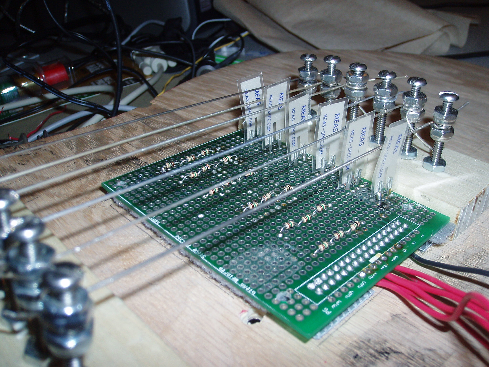
To simulate the sensation of plucking a string and obtaining the acoustic guitar sounds, we decided to use vibration sensors (Digikey, MSP1006-ND) in the form of piezo-film
elements which would produce voltage in proportion to compressive or tensile mechanical stress or strain. After proper calibration with the Aref Vcc of the MCU (5.00V), we
devised another simple circuit for these sensors whereby we connected them in parallel to three 10K resistors in series to drain the latent voltage. The individual sensors were placed touching the specific 6 strings
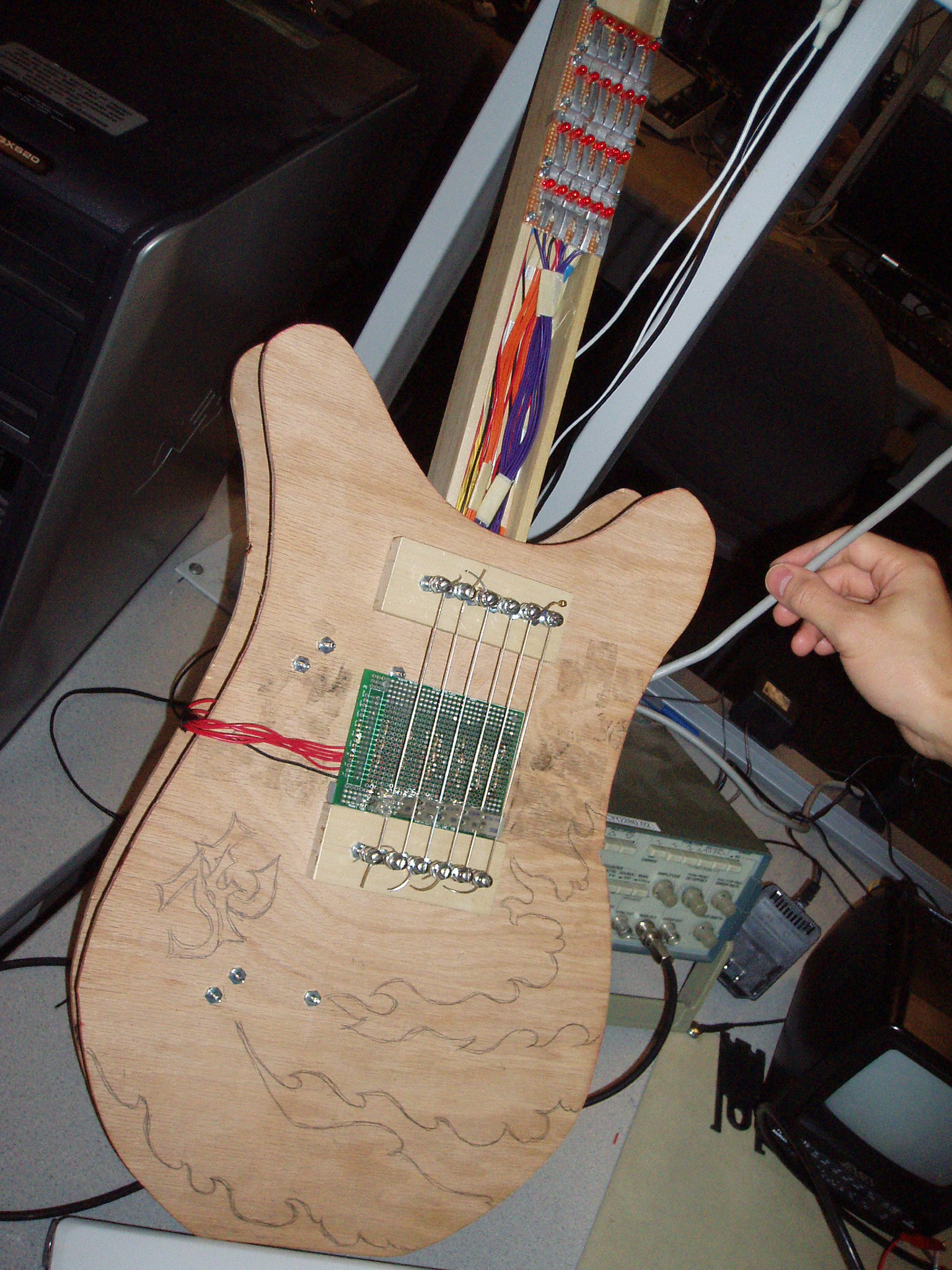
such that a sufficiently vigorous pluck would be tranferred to the sensors. The mechanical construction of the strings-suspension system was such that the strings were tightly
suspended across two screws on the front panel of the guitar, whereby they could be tightened/loosened by adjusting the nuts on the screws. A solder board containing the vibration
sensors were placed underneath these strings, with the one sensors touching a specific string.
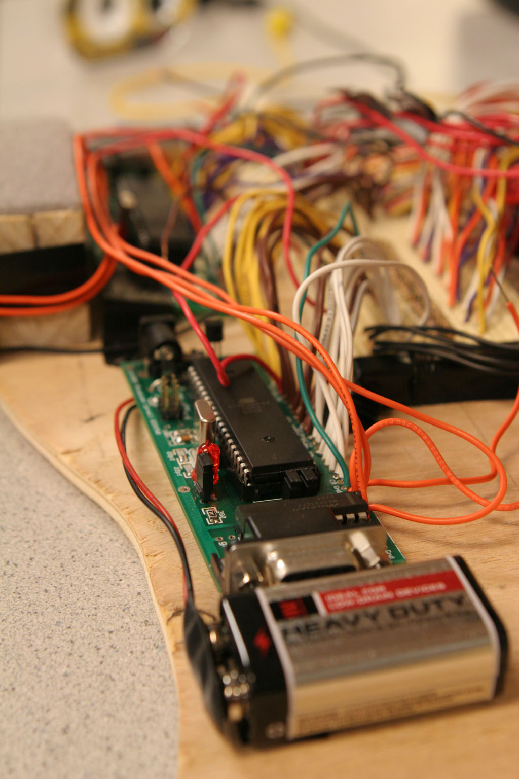
MCU/Peripherals
The inputs to the MCU would require 24 (push buttons) + 6 (vibration sensors) ports out of a total possible 32 I/0 ports in a single MCU. Of the remaining two ports, B.3 was used as
the audio signal output which would then low-pass filtered before being connected to the mono audio socket (Digikey - CP-3536-ND). The last port, D.2 was not used because we realised upon
testing that it was floated to around 3.3V. This MCU has a crystal that runs at 20MHz to provide for enough processing time for the Karplus Strong algorithm.
For the fret-position signalling circuit, we used 24 LEDs to signal the possible finger locations. We has originally considered using the LEDs both as an input and output, which would have significant reduced the ports requirement, but we realised that with the method of pressing fret positions, our fingers would naturally occlude adjacent LEDs which should not be 'depressed' which would lead to incorrect tones being played. Hence, we stuck with a push-button/LED format, and had 24 (LED) connections go to a second MCU, which then also contained 3 more connections for control push buttons (Start, Pause, Stop), as well as for RS232 connections to Hyperterm for input of guitar tabs/new chord information. The specifics would be discussed in the software design. This MCU runs on a 16MHz crystal.
Program Design
With two MCUs, separate programs were written for the specific functions required of them. For the first MCU, the program can conceptually be segmented by the timers that run the
various functions.
timer 0 runs at full speed (20MHz) in PWM mode and toggles OCR0A at full rate, basically providing the
sampling frequency for the tone to be generated. No operations are performed within this timer interrupt because we realised upon coding and testing that increasing the computation within the
interrupt inadvertently caused the interrupt speed to slow down, ultimately decreasing our sampling frequency resulting in all our generated tunes being flat.
timer 1 is used to process the Karplus Strong algorithm and is also run at full speed (20MHz). This will be described in more detail in the next subsection.
timer 2 is used for the remaining functions that concern with the sampling of inputs. This includes getFret(unsigned char), pluck(unsigned char) and debounce(void).
debounce(void) handles the effect of the vibration of the strings on the vibration sensors, pluck(unsigned char) samples the fret positions (via getFret()) and then initializes the noise
input into the delay line for the algorithm to process. We also have a function modulate() that allows hammer ons and pull offs based on a current sampling on the fret positions.
The other MCU mainly controlled the display of LEDs and the Hyperterm communications. For our user interface, we designed a bare-bones scheme which allowed for the display of the chords
of preset songs (in this case 'Happy Birthday' and 'Greensleeves') and also allows for specific learning of chords upon user request. The possible idea is to allow a user to pre-input
songs of his liking and then unplug the guitar from the computer and utilise the preset song chords to play his music at other venues.
Calibration of input sensors
For the vibration sensors we basically used the ADC of the MCU with Aref set at Vcc (5.0V) since we had checked our vibration sensors to be capable of outputting a voltage of 5.0V and
above based on the strength of the plucked excitation. Based on our calculations and testing for desired sensitivity of our strings, we decided upon a threshold of 150, corresponding roughly
to be voltage of roughly 3.0V based on ADC conversions.The sampling and corresponding debouncing of the vibration sensors was performed in debouncing() which occurred every millisecond. ADCH was
read for the six strings and an assert flag is raised if ADCH is above the threshold value of 150. Once the assert flag is raised, the procedure follows closely a debouncing procedure, but we
modified the process to oscillate between states Plucked and MaybeNoPluck for a set period of time (which we named cooldown time). The rationale of this was simple - when we initially tested the
code, we realised that the undamped vibration of the string caused multiple 'excitations' on the vibration sensors which resulted in a jarring buzz sound before the tone is played. This was
solved with the implementation of the cooldown time.
The sampling of the push buttons is simple and is carried out by functions getFret(), pluck() and modulate(). getFret() is the basic function which samples the push buttons inputs to determine any depressed button position for a specific string. pluck() and modulate() both call upon getFret for the current sampling of the push buttons. pluck() basically initializes a white noise input based on a master copy of white noise that was created during initialization, which will then be subjected to the Karplus-Strong algorithm. modulate() obtains the new positions of the push button depress and modifies the delay length of the Karplus-Strong algorithm (explained in the next subsection).
Karplus-Strong algorithm implementation
The Karplus-Strong algorithm was implemented within the interrupt of timer 1. The determination of the pitch is based on the delay line length, which is obtained from the specific
string plucked and the relevant pluck position obtained from previously mentioned functions. With the delay line length determined, the each step of the algorithm is then implemented
for every interrupt of timer 1 (20MHz) where an original value within the delay line is substituted with a new value based on the difference equation of the loop filter, y(n) = 0.5[x(n) + x(n-1)]. At
the end of the delay line, the pointer to the delay line is reset to the start. This is done for all 6 strings, which puts considerable processing-time strain per interrupt, which is why we spent a significant amount of time streamlining our code and also opting for a faster
crystal of 20MHz. The resultant signal from the 6 separate strings are summed together and scaled down accordingly before being fed out via the PWM as an audio signal.
User Interface & fret-position signalling
The user interface uses Hyperterm as well as 3 push buttons for control and interactions. The push buttons allow a player to start, pause and stop the chords being flashed on the LEDs whereas
Hyperterm allows for more flexible control as well as the ability to store chords of particular songs. The code for such a system is simple and relies on serial communications with the
requisite transmit and receive buffer. Users have a choice of being able to understand how the LED light up works, check what songs are currently stored, check what fret positions
correspond to the relevant chords, add new chords, add new songs with chords and beats as in input. If unplugged from Hyperterm, then upon pressing start, the guitar will light up
the chords for the currently selected song. The push button code is a simple assertion of LED lights to be lit depending on what chords are to be played.
Results of Design
Speed of execution
With regards to speed of execution, there are two paradigms to be concerned with. The first is concerning the response time from a pluck of a string to the sounding of a note.
For proper user interactivity, this must be suitably close such that there is the illusion that one is indeed plucking the string. In this respect, our guitar performed
excellently, with a little to no lag time between the pluck and the sound signal. This is because we allow the sampling of the strings to be at 1ms, and consequently also prevent
the buzz sound due to multiple vibrations via a cooldown period. The second concern was that of the execution speed of the processes within the interrupt. If the processing time
required between interrupts is longer than the period of the clock tick, then we would experience a decrease in the clock speed, especially with timer 0, which would result in a
erroneous production of the resultant tone frequencies. We faced this problem initially when we were developing our code, as we placed the calculations within timer 0 interrupt.
As the number of computations increased when we tried to simultaneously calculate more strings, our tone frequencies began flat. To recitfy the problem, we placed the
Karplus-Strong calculations into the timer 1 interrupt, attempted to remove redundant code and also used a 20MHz crystal instead of a 16MHz crystal. This eventually gave us the
capability to simultaneously run the algorithm for the 6 strings and give proper operation of the guitar.
Accuracy
There were 2 considerations in our project that was related to accuracy. The first was that related to the sensitivity of the vibration sensors. This would mean the minimization
of two scenarios, first the case of 'false alarms', where other strings are triggered upon the rigorous pluck of one string perhaps due to residual vibration across the solder
board, and second, the case of lack of sensitivity where strings lack to responsivity expected of a conventional guitar. With regards to such specifications, we attempted to
reach a satisfactory compromise by adjusting the threshold of strings individually as well as ensured that the solder board is firmly attached to the guitar panel using velcro
straps. We realised that with proper soldering and secured attachment to the guitar panel, we were able to ensure the accurate sensitivty of each of the strings. The other
consideration involved that our accuracy of the tone frequencies. To that end, we realized that our higher tones were often slightly off-tune due to an issue with the Karplus-Strong
algorithm itself. We realised from Jaffe and Smith's paper that tuning was off, especially for higher frequencies due to the enforced interger length of the delay line, which
dictates certain 'allowable' tone frequencies to be produced. To rectify this problem, we would need to implement a 'tuning filter', something which we felt would increase the
computational load at the timer 1 interrupt and hence we decided to accept the slight tuning inaccuries brought about by the basic algorithm.
Safety, Interference and Usability
In general, all electronic parts are kept between the two panels of the guitar body (except the plucking circuit) and are isolated from the user which allows for general safety
for the user. Also, we left the sides of the guitar open to prevent any incidence of possible overheating. We did not generate any interference with other people's designs
besides perhaps some sort of noise pollution during our testing phase. The guitar is meant to be very user friendly, since the LED-based fret-position signalling mechanism
is aimed at teaching new guitar players to play chords as well. Our aim was to make the guitar as portable, light and user-friendly as possible and we felt that we managed
to achieve this somewhat since the guitar can essentially be played without any power source (we used 9V batteries) and was not too heavy as well.
Conclusion
Expectations & Analysis of Design
We were pleased with the results of our project as the guitar was capable of playing realistic tones and certainly gave the illusion of playing an actual acoustic guitar.
Similarly, the good response time between the pluck of the string and the sounding of the notes allowed for a realistic playing experience. Such a basis of operability means
that additional features unavaible to conventional guitars can be easily implemented to great success.Furthermore, we were pleased with the user interface we created, since it
really does have improvements from a conventional guitar, allowing for quick learning of guitar chords and songs. Hence, we felt that we had achieved what we set out to do.
In terms of what we might do differently, I think in general we should have considered the magnitude of our project carefully before fully committing ourselves to it, because
we felt indeed that having to contend with 24 push buttons and LEDs was quite an huge hardware task. It eventually limited us in terms of the amount of new features we could
implement on our guitar because we had spent a large amount of time first in getting six iterations of Karplus-Strong to work, then in calibrating the vibration sensors, and
finally in error checking for all the 24 input/output ports.
Also, we felt like we should have allowed for communications between both our MCUs since it would have provided more opportunity for sync between inputs and outputs system
(perhaps to first demonstrate how a particular song should sound like along with the correct fret positions) or perhaps to lighten the computation load of one MCU and hence
achieve better tonal quality of sounds produced.
Standards & Intellectual Property Considerations
Our design did not need to contend with the standard because it did not involve the 440Hz A note that was stated in ISO 16:1975. In terms of intellectual property
considerations, our code is all original, besides drawing upon the fundamental Karplus Strong algorithm. We do feel that our project, despite having much programming
possbilities and extensions, is ultimately not a novel creation and does not merit publication.
Ethical & Legal Considerations
In terms of ethical considerations, we felt that we closely adhere to all the conditions set forth in the IEEE code of ethics, and since there wasn't any potential conflict
and competition, most of the considerations were not of an issue. Our design did not pose any form of danger to anyone and hence we did not need to disclose any factors
to the public. In our dealing with vendors, we established a clear understanding in terms of the aims and restrictions of our project, and any parts offered was
recommended first by the course itself. We aimed to help all our coursemates with any form of help and expertise we could offer and did not dsicriminate against anyone
based on race, religion, gender, disability, age or nation. In terms of being honest and realistic in stating claims or estimates based on available data, we have
remained honest in reporting all incidences with respect to the project and our cost report likewise is an accurate estimation of the cost of materials we used. Finally, we
also graciously accepted and gave honest criticisms to our coursemates who worked closely with us and have attempted to credit whatever help we obtained via the contribution
of others.
In terms of legal considerations, we felt like there was none whatsoever to speak of owing to the field of interest we were dealing with.
Appendix
Program Listing
synthesizer.c (MCU Input) | segovia.c (MCU output)
Schematics
Cost Report
| Item, Description | Mfg or Vendor | Cost Each | Qty | Subtotal |
|---|---|---|---|---|
| $73.18 | ||||
| Atmega644, Microcontroller | Atmel | $8.00 | 2 | $16.00 |
| Custom PC Board | Lab | $4.00 | 2 | $8.00 |
| RS232 Connector | Lab | $1.00 | 1 | $1.00 |
| 9V Battery | -- | $2.00 | 2 | $4.00 |
| Small Solder Board | Lab | $1.00 | 4 | $4.00 |
| DIP Socket | Lab | $0.50 | 3 | $1.50 |
| SIP/header/socket/plug | Lab | $0.05 | 5 | $0.25 |
| Max232 CPP | Maxim | scavenged | 1 | $0.00 |
| Pushbutton, P13588S-ND | Digikey | $0.376 | 24 | $9.024 |
| Piezo Film Elements, MSP1006-ND | Digikey | $2.40 | 6 | $14.40 |
| Audio Socket (Mono), CP-3536-ND | Digikey | $0.58 | 1 | $0.58 |
| LEDs | Lab | $0.14 | 24 | $3.36 |
| Computer Speakers | -- | self owned | 1 | $0.00 |
| Materials, Wood | Lowe's | $6.32 | -- | $6.32 |
| Materials, Screws | Lowe's | $4.75 | -- | $4.75 |
| White Board | self owned | -- | 1 | -- |
Task Breakdown
| TASK | GROUP MEMBER |
|---|---|
| Construction of Guitar Neck/Body | Justin |
| Push Buttons/LEDs Connections | Justin |
| Vibration Sensors Connections | Frank |
| Soldering/MCU Connections/Peripherals | Justin/Frank |
| Karplus-Strong Algorithm | Joel/Frank |
| Calibration of Inputs | Joel |
| User Interface | Joel |
| Software | Joel |
| Debugging/Testing | All |
| Report/Webpage | Frank |
References
Datasheets:
1. Push Buttons, Digikey, P13588S-ND
2. Piezo Film Sensors, Digikey, MSP1006-ND
Karplus-Strong algorithm references:
1. Karplus, Kevin, and Alex Strong. 1983. "Digital Synthesis of Plucked-String and Drum Timbres." Computer Music Journal 7(2): 43-55.
2. Jaffe, David, and Julius O. Smith. 1983. "Extensions of the Karplus-Strong Plucked-String Algorithm." Computer Music Journal 7(2): 56-69.
More Information
You can visit the ECE 4760 course website or contact Joel Ong (jyo2), Frank Chen (flc23) or Justin Leow (jl574).