Wii-C
(Wii Conductor)
Michael Ostrander (mco26)
Samuel Fanfan (sf85)
Introduction
Our project can be described as a simplified implementation of
Wii-Music, utilizing a Nintendo Wii Remote (Wiimote) to play a
gesture-based music game with the player as a virtual music conductor.
We decided to do this project since it exploited two of the
Wiimotes more peculiar features: its wand-like shape and the embedded 3-D
accelerometers. Interfacing the Wiimote with a microcontroller (MCU), we
wirelessly transmit motion gestures and button pushes to the MCU. The MCU
uses these inputs to create sound by means of Direct Digital Synthesis
(DDS). Sound is generated whenever the user moves the controller in an
up-and-down motion, in true conductor fashion. The sound can be then
listened through the connected audio playback device. All of this is done
in real time, with all components operating in parallel. Also, since there
is little documentation on interfacing the two devices, our project
doubles as a guide for future students wishing to do a Wiimote
project.
Inspiration
Our original idea was to create a wireless glove interface for
cellular phones that operated over Bluetooth. Unfortunately we couldnt find a
Bluetooth module that met the specifications we needed (supported the HSP
profile, could transmit data serially, AND fit within our $75 budget). Still
wanting to do a Bluetooth-related project, we decided on the Wiimote since
groups from previous years proved its possible. The idea for a gesture-based
music game came after we witnessed another group's attempt to
simulate the movements of a conductors stick (whose permission we made
sure to obtain before implementing our idea).
High Level Design
Background Math - DDS Sound Production
The output sound
is produced by a method called direct digital synthesis (DDS). Timer0 is set up to create a pulse
width modulated (PWM) signal, through the timer0 overflow ISR. The duty cycle, which is
determined by the OCR0A register, is cyclical, following a sine wave. The frequency of the output sound
is determined by the frequency of the sine wave. For a 32-bit DDS accumulator,
running at 16 MHz, the frequency of the sine wave, called the increment
in our program, can be calculated by the following
formula:
Increment = 2^32*Fout/(16*10^6/2^8) = 68719 * Fout
(1),
where Fout is the
desired frequency of the output signal. In order to make the output sound better, it
is put through a low-pass filter, which converts the output square wave
into a sine wave (or sum of sine waves if the output is composed of
two or more frequencies).
We use a simple first order low pass filter, with R and C values
producing a cutoff frequency of roughly 1600 Hz, which is about the same
as our highest frequency.
Additionally, the signal is ramped up at the beginning and ramped down at the end in order to remove a glitch (slight click noise) that would otherwise occur. This is achieved by creating a ramp table, and then multiplying this and the sine value together to create a revised OCR0A value.
Logical Structure
Going from gesture to audio output requires several intermediate steps.
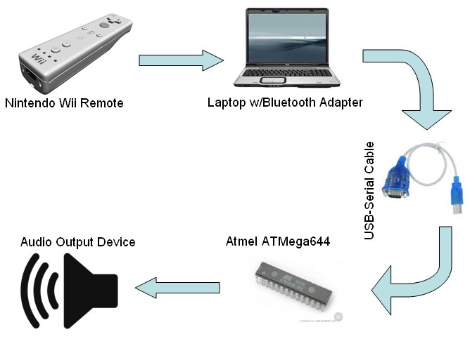
Figure 1. High Level Block Diagram
Prior to data transfer, the Wiimote is linked wirelessly to the laptop via a Bluetooth adapter. The adapter needs to support the Human Interface Device (HID) profile to establish a proper connection. The second figure depicts what happens to the wireless data when it reaches the Laptop stage. After being received by the adapter, the data is captured by GlovePIE and sent to a Visual Basic program via the Open Sound Control protocol. This program is necessary since GlovePIE cant directly transfer data over RS232. Once inside the Visual Basic script, the data is parsed into a usable format for the MCU. Next the data is transferred from Visual Basic to the USB-Serial cable. From there, the parsed data is received by the MCU through a serial connection. The MCU uses the inputted data to create sound based on internal algorithms and state machines. Finally the created sound is played through the connected audio device.
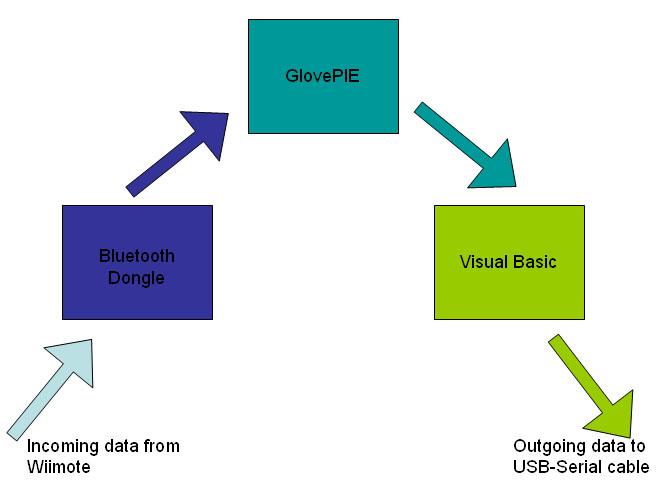
Figure 2. Block diagram of data flow within laptop
Patents, Copyrights, Trademarks, and Intellectual Properties
Our project incorporates several patents, intellectual
properties, and trademarks. Nintendo Company Ltd. owns the rights to the
Wii Remote controller, Visual Basic 6.0 is an intellectual property of The
Microsoft Corporation. BlueSoleil and GlovePIE are both freeware and
intellectual properties of the IVT Corporation and Carl Kenner,
respectively. Lastly, our Bluetooth dongle is patented by Iomega, a
subsidiary of the EMC Corporation. Since we never modify any of these
components there arent any real considerations to be made.
The prototype board that we used for the ATmega644 was
designed and laid out by ECE 476 Professor Bruce Land. The initial test
code for the prototype board and the UART code used for initializing
serial communications were provided as part of earlier labs in ECE
476.
Standards incorporated in our design
Our project references numerous standards, most of
which are communication protocols. Some of these communication protocols
include Bluetooth, OSC, UDP, and RS-232. Most of these were handled automatically
by the various programs we wrote, so long as we followed the appropriate
initialization procedures. One additional standard that we used
was for outputting sounds is known as dual tone multi-frequency
(DTMF).
This is the
protocol used for outputting sounds that would mimic those produced by a
phone.
Software design
Wiimote <-> Laptop Connection
The bulk of our final project, as well as the part
that took the most work to design, is our software section. The high
level path that data follows begins with accelerometer and button push
data being transmitted via Bluetooth from the Wiimote to a program called
GlovePie, which runs on a laptop. We use a USB Bluetooth dongle and
BlueSoleil drivers. Unfortunately, the Wiimote is
incompatible with the inherent Microsoft Bluetooth stack, so the
BlueSoleil drivers were required. Luckily, BlueSoleil has a free trial
version of their drivers, so this was not a large issue. Once the
Wiimote is connected to the laptop, GlovePie is started.
GlovePie
GlovePie was developed by Carl Kenner, in order to
facilitate data acquisition of wireless controllers, for example the
Wiimote.
Programs (with extensions .PIE) are written in a very simple
language, similar to C. Following examples that were downloaded
along with GlovePie, we easily created a program that acquired the data
that we wanted to send to the microcontroller. The first
issue we ran into while creating the script was how to do anything with
the data.
Once the data was obtained by GlovePie, it should then be sent to
the microcontroller via a serial connection. We soon
discovered that the only way to export data was through a function called
sendOSC(), which could send data to a specific IP address/network port
number in the Open Sound Control (OSC) format. After
researching the differences between network ports and serial ports, we
determined that there was no way to send this OSC data directly to the
microcontroller.
GlovePie <-> Microcontroller
We then researched different methods of transferring this data from network input to serial output and came up with Visual Basic (VB). VB can listen on a specific network port for incoming data, as well as send data to a specific serial port, which is exactly what we needed. Implementing this crucial step was actually much more difficult than it sounded. Even with numerous guides found online, setting up the input and output sections were difficult to create and debug. When we first began, we looked up every facet of the OSC network protocol, along with serial RS-232 protocol. Unfortunately, this was in vain due to the fact that VB automatically converts the data to and from these protocols without even being told to. Our final GlovePie script obtains six values from the Wiimote, and sends them to the VB program, which then obtains these values, parses them, and sends them on to the microcontroller.
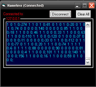
Figure 3. Our Visual Basic script capturing real-time data
Microcontroller design
At this point, we were back in familiar territory
with respect to the programming language. We wanted to design a direct-digital
synthesis (DDS) system that would be triggered by the user controlled
Wiimote.
Thus, we set up pulse width modulation (PWM) to produce the sound,
using the timer0 overflow ISR, as well as the receive ISR to read the data
from VB.
In addition to these two interrupts, we added a state machine that
would compare how the up and down acceleration of the Wiimote changes, in
order to determine when a sound should be played. To reiterate
this part of the design, a sound will be played whenever the user moves
the Wiimote down and then up (at the bottom of the movement), similar to
how a conductor moves his baton. Our program evolved to include button
push inputs, which would do a variety of things. In our final
design, we have five buttons: A, B, minus, home, and plus. The minus,
home, and plus buttons change what mode the program runs in. Each mode
will produce different types of sound.
Default mode, mode 2, or home mode:
In an effort to produce a sound similar to a guitar
strumming, we made each output pitch include both its first and third
harmonics (with appropriately scaled amplitudes). In this mode,
the A and B buttons increase and decrease, respectively, the pitch of the
fundamental frequency in half steps. The range is limited to the 13 notes
between middle-C and an octave above middle-C, inclusive.
Phone mode, mode 3, or plus mode:
This mode produces the dual-tone multi-frequency
(DTMF) sounds that we first experimented with in lab2. In this mode,
the A and B buttons cycle through the 12 different possibilities of sounds
(1-9, *, 0, #).
Song mode, mode 1, or minus mode:
This mode allows the user to conduct a simple song
(Row, Row, Row Your Boat). In this mode, the B button is
disabled.
The A button must be pushed before any sound can occur: it is the
signal that the user is ready to begin the song. The idea of
this mode is that every time the user moves the Wiimote down and then up,
the output will move to the next note in the song. Once
completed with the song, the program will automatically move back to the
default mode.
In addition to this, we also included the
uart.c/uart.h files in the project, in order to utilize the serial
connection between the microcontroller and Visual Basic.
DDS sound production
Timer0 is set to fast PWM mode, which creates an
output of a square wave on pin B.3, with a pulse width proportional to
OCR0A.
Thus, in order to create a wave with a given frequency, we change
OCR0A once every timer0 overflow ISR, based upon a sine table. As well, this
output is put through a low pass filter (detailed above). In order to
increase the quality of the sound, the signal is ramped up at the
beginning, and ramped down at the end. This ramping is achieved by multiplying
the OCR0A value by a value from a ramp table, which is initialized in
initialize().
However, if a user decides to play another note before the previous
has finished, no ramping will occur between the two notes. Instead, all
sound is cut off for 5 ms, after which, it returns to regular output. This creates
a slight pulse of no sound, which is desirable in order to signal to the
user when they begin a new note, even if it is the same pitch as the
previous.
For more detailed information regarding the various programs we wrote, refer to the commented code in Appendix A.
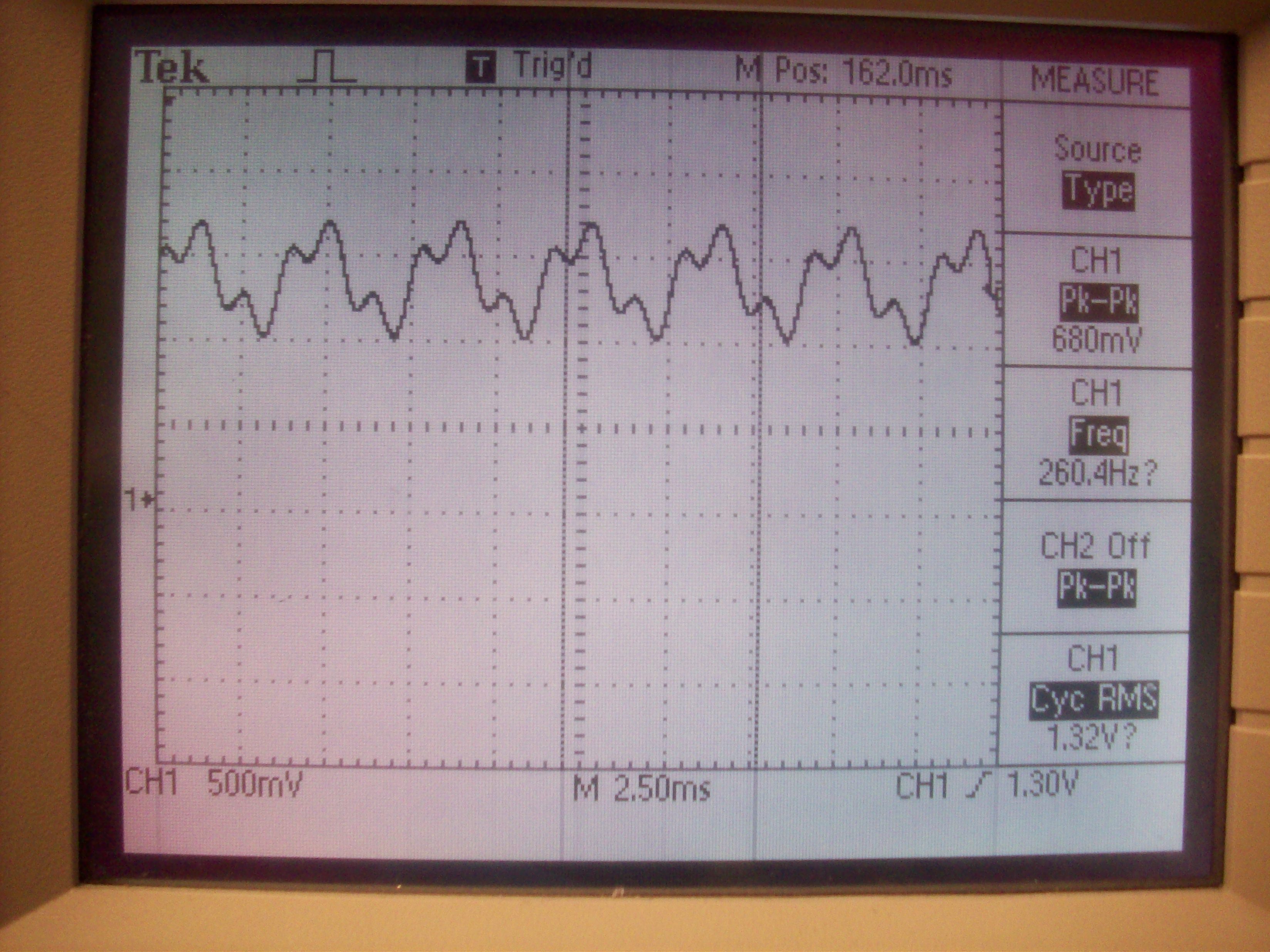
Figure 4. Sample out of DDS sound generation
Hardware design
Wiimote
The hardware side of our project is much less extensive than the software. The first hardware component in the project is the Wiimote. It is a standard wireless joystick device from Nintendo, built to go along with the Wii gaming console. It has a built-in Bluetooth transceiver, which includes the Human Interface Device (HID) profile. We use this profile in order to communicate with it via Bluetooth.
Laptop
The next piece of hardware is the laptop we use. In order to transfer data from GlovePie to the microcontroller, the data must be sent to an internal network port, and then outputted to an external serial port (in this case, we used a USB to serial connector). VB has add-ons to handle both of these protocols, so we didnt have to do anything regarding the actual hardware inside the laptop, luckily.
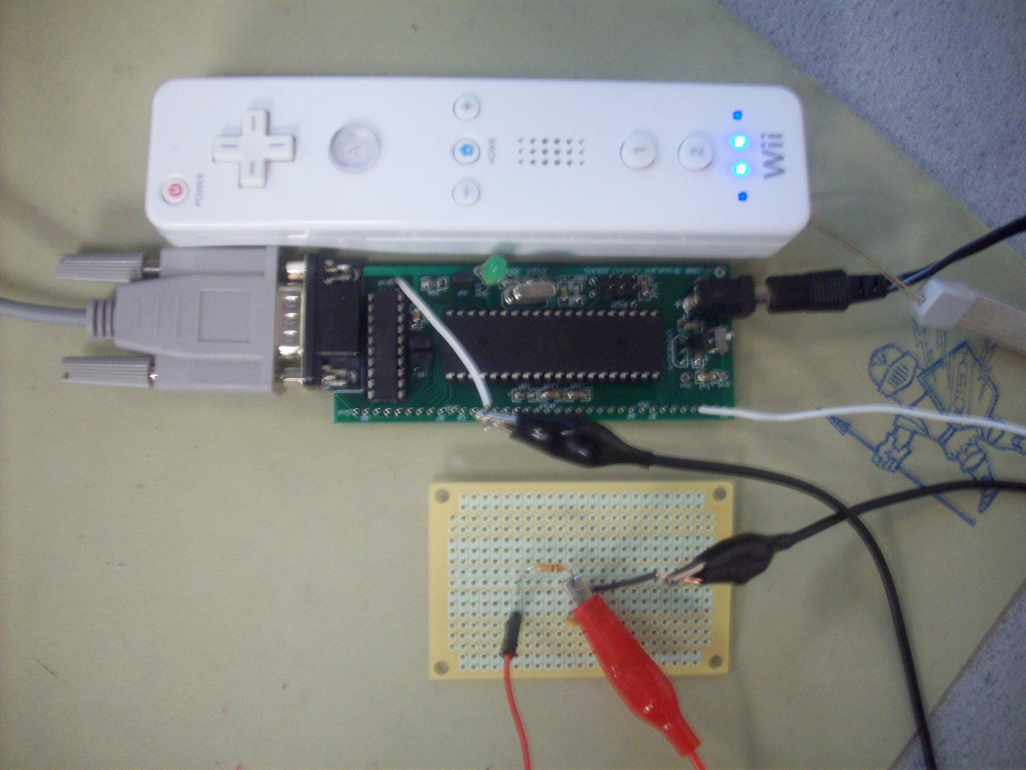
Microcontroller
Finally, the data arrives at the microcontroller. We decided to create a custom PC board, since it could handle all of the hardware/software issues we needed it to. Using the custom PC board from the previous year, we soldered on all of the usual things according to the how-to on the ECE 476 website, including the mounts for the chip, the power supply, resistors, capacitors, 16 MHz clock, etc. In addition, we needed to be able to communicate with a serial cable, so we added the serial connection and Max233 chip mounts as well.
Debugging
However, when actually testing the program, we used the STK board instead. This was due to our limited debugging ability. Since we were using the serial cable to receive data from the Wiimote, we couldnt utilize the uart output to hyperterm. Thus, all we had was the sound output (if it was working during the current version) and the 8 LEDs on the board. This was one of the most frustrating aspects of the entire project because it cut down our ability to debug so much. When possible, we hardcoded test data into the code, and used the serial cable instead to connect to hyperterm, but in the later testing runs, this proved completely ineffective, as most hard-coded data had to include delays, which blocked the dds-producing ISR.
Sound Output
The dds output data can be played on an array of
sound producing devices, from headphones to speakers to TVs. For testing,
we used a black and white TV provided in lab.
Results of the design
Accuracy/Timing Issues
One of the main problems to overcome during our
testing was data flow speed. The slowest communication path was the
RS-232 communication link, running at around 1 byte of information per
millisecond.
If the accelerometer data was transmitted too slowly, the user
would have a hard time getting the microcontroller to detect that a sound
should be played. Thus, we had to make sure that we were
only transmitting data that was essential to our project, while still
allowing each section to be able to parse the data correctly. Our final
project sends 18 bytes every 30 milliseconds, which turns out to be 6000
bits per second (each byte of information also includes a start and end
bit).
With a maximum baud rate of 9800, we could afford to increase the
transfer rate by a bit. However, testing at a higher rate
caused inexplicable bugs in our program, so we decided to keep it where it
was.
Since accuracy is very important, we ran a series of tests in order to determine the hit/miss rate of a user conducting. Out of 100 movements, there were 2 movements that didnt sound when they should have and 4 sounds that occurred when they shouldnt have. For a rather slow mode of communication (the serial connection), a 94% hit percentage, with a 4% false-hit percentage is rather good.
Interference
Our design transmits data over a secure, globally unlicensed short range radio frequency band (2.4 GHz). Due to the unlicensed nature of this band, any interference we might cause is within our rights. Also, this opens the door to security issues, however we decided not to go into this for our project. Due to the Bluetooth protocol and way that a Bluetooth device binds to another device, there is a very small percentage that any interference would result, anyway.
Usability/Safety
The Wiimote has no usability issues, mostly due to the clever design by Nintendo. Additionally, there are very few safety issues. One possible concern is due to sound output: if the output is too loud, it could damage users ears. Also, if the speaker is not compatible with the output voltages, there could be damage to the microcontroller and/or the speaker.
Conclusion
Expectations versus results
Our design has evolved greatly over the course of the
project.
Due to little documentation on the subject, establishing the
connection between our Wiimote and microcontroller (MCU) took up the bulk
of our time. Since most of our effort was spent determining how to connect
the two devices we had to make a few design compromises to meet our
deadline. One such software compromise was concerning how the pitches of
notes change.
We originally wanted everything to be gesture-based, including how
the pitch would change, but we changed this to be controlled by button
pushes instead, due to the lack of time available to test this
feature.
However, we did meet our expectation of laying a
foundation for future groups interested in using the Wiimote in a
project.
Time and documentation are two of the most limiting factors to any
project. As discussed above, we were frustrated again and again by the
lack of documentation concerning the Wiimote. Even prior
ECE 476 groups who used the Wiimote were very vague in their descriptions
of communication between the Wiimote and the microcontroller. Thus, our
project doubles as a guide for future students wishing to design a Wiimote
project - the connection scheme is robust and easy to integrate. This will not
only save precious time and effort, but also give students time to
experiment with the software and exploit all of its features.
Future considerations
Since establishing the communication link between the
Wiimote and MCU took the bulk of our time, many desired features were
compromised in an effort to meet our deadline. Suggestions for future
implementations of this project would include:
-Incorporating data from all three accelerometers to
make the game fully gesture-based.
-Development of a better algorithm to parse the
accelerometer data.
-Development of the sound portion, incorporating real
instrument sound generation instead of generating pure tones.
-Possibly adding a video element to the project, like
writing musical notes to a music sheet in real time.
-Using a serial Bluetooth module to make the project
fully portable.
Standards incorporated in
our design:
As mentioned in the High Level Design section, we
referenced many different standards of communication in our final project,
including Bluetooth, OSC, UDP, and RS-232. As well, the Wiimote and drivers of
Bluetooth communication are commercially available products, and most
likely reference additional standards that are unknown specifically to
us.
Finally, the DTMF standard is used when outputting DTMF tones.
Ethical
Considerations:
Throughout the course of the final project, we
adhered to the IEEE Code of Ethics at all times. Although we were at times jerking the
Wiimote around in order to produce a sound, we used the attached strap, so
that even if we lost control of the device, it would not fly out of our
reach and do damage to a person or someones property. When we were
producing sound on the TV, we were aware of our surroundings, and kept the
volume as low as we could, while still being able to fully test what we
needed.
One of our main considerations when undertaking this project was to
be able to create a foundation for future groups if they had interest in
using the Wiimote. In this way, we have, hopefully, helped
to foster a future group of students that will take what we have done and
continue to build it into something great.
Legal considerations:
We do not intend to sell or market this product. Other than providing it as a source of reference for future groups, our project shouldnt pose any legal issues.
Appendices
Appendix A:
GlovePie Script:
Wiimote.Led1 = false
Wiimote.Led2 = true
Wiimote.Led3 = true
Wiimote.Led4 = false
If Wiimote.A = True
var.Apush = 1
Else
var.Apush =
0
End if
var.Bpush = 1
Else
var.Bpush =
0
End if
var.Uppush = 1
Else
var.Uppush
= 0
End if
var.Downpush = 1
Else
var.Downpush = 0
End if
var.Leftpush = 1
Else
var.Leftpush = 0
End if
var.Rightpush = 1
Else
var.Rightpush = 0
End if
var.Minuspush = 1
Else
var.Minuspush = 0
End if
var.Homepush = 1
Else
var.Homepush = 0
End if
var.Pluspush = 1
Else
var.Pluspush = 0
End if
var.Onepush = 1
Else
var.Onepush
= 0
End if
var.Twopush = 1
Else
var.Twopush
= 0
End if
var.sendData = "" +
RemoveUnits(Wiimote.RelAccX) + " " + RemoveUnits(Wiimote.RelAccX) + " " +
RemoveUnits(Wiimote.RelAccX) + " " + RemoveUnits(Wiimote.Roll)+ " " +
var.Apush+" " +var.Bpush+" " +var.Uppush+" " +var.Downpush+" "
+var.Leftpush+" " +var.Rightpush+" " +var.Minuspush+" " +var.Homepush+" "
+var.Pluspush+" " +var.Onepush+" " +var.Twopush
SendOsc("127.0.0.1", 777,
var.sendData)//RemoveUnits(Wiimote.RelAccX))
Visual Basic Script:
Option Explicit
Dim data As String
'Clears Text2
Private Sub Command2_Click()
Text2.Text = ""
End Sub
'Initialization procedure
Private Sub Form_Load()
Dim hellomsg
hellomsg = MsgBox("Welcome. To start using the" + Chr$(10) _
+ "program please press OK." + Chr$(10) _
+ "Otherwise hit cancel to exit", vbOKCancel, "Nameless")
If hellomsg = 2 Then
Unload Me
Exit Sub
End If
'Sets up MSComm1 (which is the serial port)
' and Winsock1 (which is the network port)
If MSComm1.PortOpen = True Then
MSComm1.PortOpen = False
End If
With MSComm1
.CommPort = 6 'PORT6, sometimes changes, depending where serial cable is connected
.Settings = "9600, N, 8, 1"
.DTREnable = False
End With
With Winsock1
.RemoteHost = "127.0.0.1"
.RemotePort = "778"
.LocalPort = "777"
End With
End Sub
'Occurs if the user pressed the Connect/Disconnect button
Private Sub Command1_Click()
If Command1.Caption = "Connect" Then
On Error GoTo errhandler
Winsock1.Bind Winsock1.LocalPort 'Starts up UDP network connection
MSComm1.PortOpen = True 'Starts up serial connection
Timer1.Interval = 30 'Starts up timer that will send data along the serial connection
Form1.Caption = "Nameless (Connected)"
Command1.Caption = "Disconnect"
Label1.Caption = "Connected to"
Frame1.Caption = Winsock1.LocalIP
Exit Sub
End If
If Command1.Caption = "Disconnect" Then
Winsock1.Close 'Closes UDP network connection
Timer1.Interval = 0 'Disables timer that will send data along the serial connection
MSComm1.PortOpen = False 'Closes serial connection
Command1.Caption = "Connect"
Form1.Caption = "Nameless (Disconnected)"
Label1.Caption = "Not Connected"
Frame1.Caption = ""
Exit Sub
End If
errhandler: 'occurs if there was a problem while connecting to network port or serial port
MsgBox "Failed to connect!", vbCritical
End Sub
'Occurs when data comes in on network port
Private Sub Winsock1_DataArrival(ByVal bytesTotal As Long)
'Stores data in a buffer until it is parsed
Winsock1.GetData data
Frame1.Caption = Winsock1.RemoteHostIP
End Sub
'parses buffer that stores data from GlovePie
'sends the parsed data along to the microcontroller
Private Sub Timer1_Timer()
Dim comma1 As Integer
Dim comma2 As Integer
Dim comma3 As Integer
Dim comma4 As Integer
Dim comma5 As Integer
Dim comma6 As Integer
Dim comma7 As Integer
Dim comma8 As Integer
Dim comma9 As Integer
Dim comma10 As Integer
Dim comma11 As Integer
Dim comma12 As Integer
Dim comma13 As Integer
Dim comma14 As Integer
Dim comma15 As Integer
Dim sendData As String
comma1 = InStr(Mid$(data, 2), Chr$(32))
comma2 = InStr(Mid$(data, 2 + comma1), Chr$(32))
comma3 = InStr(Mid$(data, 2 + comma1 + comma2), Chr$(32))
comma4 = InStr(Mid$(data, 2 + comma1 + comma2 + comma3), Chr$(32))
comma5 = InStr(Mid$(data, 2 + comma1 + comma2 + comma3 + comma4), Chr$(32))
comma6 = InStr(Mid$(data, 2 + comma1 + comma2 + comma3 + comma4 + comma5), Chr$(32))
comma7 = InStr(Mid$(data, 2 + comma1 + comma2 + comma3 + comma4 + comma5 + comma6), Chr$(32))
comma8 = InStr(Mid$(data, 2 + comma1 + comma2 + comma3 + comma4 + comma5 + comma6 + comma7), Chr$(32))
comma9 = InStr(Mid$(data, 2 + comma1 + comma2 + comma3 + comma4 + comma5 + comma6 + comma7 + comma8), Chr$(32))
comma10 = InStr(Mid$(data, 2 + comma1 + comma2 + comma3 + comma4 + comma5 + comma6 + comma7 + comma8 + comma9), Chr$(32))
comma11 = InStr(Mid$(data, 2 + comma1 + comma2 + comma3 + comma4 + comma5 + comma6 + comma7 + comma8 + comma9 + comma10), Chr$(32))
comma12 = InStr(Mid$(data, 2 + comma1 + comma2 + comma3 + comma4 + comma5 + comma6 + comma7 + comma8 + comma9 + comma10 + comma11), Chr$(32))
comma13 = InStr(Mid$(data, 2 + comma1 + comma2 + comma3 + comma4 + comma5 + comma6 + comma7 + comma8 + comma9 + comma10 + comma11 + comma12), Chr$(32))
comma14 = InStr(Mid$(data, 2 + comma1 + comma2 + comma3 + comma4 + comma5 + comma6 + comma7 + comma8 + comma9 + comma10 + comma11 + comma12 + comma13), Chr$(32))
comma15 = InStr(Mid$(data, 2 + comma1 + comma2 + comma3 + comma4 + comma5 + comma6 + comma7 + comma8 + comma9 + comma10 + comma11 + comma12 + comma13 + comma14), Chr$(32))
Dim xAcc As Integer
Dim yAcc As Integer
Dim zAcc As Integer
Dim roll As Integer
Dim aPush As Integer
Dim bPush As Integer
Dim uPush As Integer
Dim dPush As Integer
Dim lPush As Integer
Dim rPush As Integer
Dim mPush As Integer
Dim hPush As Integer
Dim pPush As Integer
Dim oPush As Integer
Dim tpush As Integer
If MSComm1.PortOpen = True Then
If comma1 > 0 And comma2 > 0 And comma3 > 0 And comma4 > 0 Then
xAcc = 1 / 16 * Val(Mid$(data, 2, comma1 - 4) + Mid$(data, 1 + comma1 - 2, 2))
yAcc = 1 / 16 * Val(Mid$(data, 2 + comma1, comma2 - 4) + Mid$(data, 1 + comma1 + comma2 - 2, 2))
zAcc = 1 / 16 * Val(Mid$(data, 2 + comma1 + comma2, comma3 - 4) + Mid$(data, 1 + comma1 + comma2 + comma3 - 2, 2))
roll = 1 / 20 * Val(Mid$(data, 2 + comma1 + comma2 + comma3, comma4 - 4))
aPush = Val(Mid$(data, 2 + comma1 + comma2 + comma3 + comma4, 1))
bPush = Val(Mid$(data, 2 + comma1 + comma2 + comma3 + comma4 + comma5, 1))
uPush = Val(Mid$(data, 2 + comma1 + comma2 + comma3 + comma4 + comma5 + comma6, 1))
dPush = Val(Mid$(data, 2 + comma1 + comma2 + comma3 + comma4 + comma5 + comma6 + comma7, 1))
lPush = Val(Mid$(data, 2 + comma1 + comma2 + comma3 + comma4 + comma5 + comma6 + comma7 + comma8, 1))
rPush = Val(Mid$(data, 2 + comma1 + comma2 + comma3 + comma4 + comma5 + comma6 + comma7 + comma8 + comma9, 1))
mPush = Val(Mid$(data, 2 + comma1 + comma2 + comma3 + comma4 + comma5 + comma6 + comma7 + comma8 + comma9 + comma10, 1))
hPush = Val(Mid$(data, 2 + comma1 + comma2 + comma3 + comma4 + comma5 + comma6 + comma7 + comma8 + comma9 + comma10 + comma11, 1))
pPush = Val(Mid$(data, 2 + comma1 + comma2 + comma3 + comma4 + comma5 + comma6 + comma7 + comma8 + comma9 + comma10 + comma11 + comma12, 1))
oPush = Val(Mid$(data, 2 + comma1 + comma2 + comma3 + comma4 + comma5 + comma6 + comma7 + comma8 + comma9 + comma10 + comma11 + comma12 + comma13, 1))
tpush = Val(Mid$(data, 2 + comma1 + comma2 + comma3 + comma4 + comma5 + comma6 + comma7 + comma8 + comma9 + comma10 + comma11 + comma12 + comma13 + comma14, 1))
sendData = Str(yAcc) + Chr$(32) + Str(aPush) + Chr$(32) + Str(bPush) + Chr$(32) + _
Str(mPush) + Chr$(32) + Str(hPush) + Chr$(32) + Str(pPush) + Chr$(59)
Text2.SelText = sendData 'prints data to window
MSComm1.Output = sendData 'sends data to microcontroller via serial
End If
End If
End Sub
'Occurs when the user quits the program
Private Sub Form_Unload(Cancel As Integer)
MsgBox "Thank you for" + Chr$(32) _
+ "using our program"
End Sub
Microcontroller Program:
#include <stdio.h>
#include <avr/io.h>
#include <avr/interrupt.h>
#include "uart.h"
#include <util/delay.h>
#include <string.h>
#include <math.h>
#define pitchCounterMax 20 //defines how often the change-pitch state machine is called
volatile char pitchCounter; //countdown counter to change-pitch state machine
#define accCounterMax 30 //defines how often the accelerometer data is polled
volatile char accCounter; //countdown counter to accelerometer-polling function
#define noteDuration 500 //defines the duration of a note
volatile int noteCounter; //countdown counter to when a note is finished
#define soundLimit 40 //acceleration threshold to play a note
//note duration must be greater than 250
#define countMS 62 //62 ticks of the ISR per millisecond
volatile char count; //counter that helps produce the millisecond timer
volatile char h; //temp variable for serial input
volatile char buffer[30]; //buffer from serial input
volatile char buffer_index; //indicates number of elements in buffer
volatile signed int yAcc; //y acceleration
volatile signed char val_yAcc[5]; //previous 5 y accelerations
volatile char state_yAcc[5]; //previous y acceleration states (state = 1 if yAcc>0, state = 0 if yAcc<0)
char A,B,minus,home,plus; //various variables that correspond to buttons on the Wiimote (1=pushed, 0=not pushed)
unsigned int i; //counter for producing various tables
volatile char stringRdy; //indicates to main that there is an input string that is ready to parse
volatile char rampCount; //how far through the ramping the program is
volatile char rampUp; //indicates whether ramping should occur
volatile char silence; //state variable for giving a pulse if a note is re-applied before the previous note is finished
char pitchMax; //maximum number of pitches in whatever mode the program is in
char pitch; //which pitch to play (# between 0 and pitchMax-1)
char pitchState; //state variable to be used in the change-pitch state machine
char flag; //to be used in the change-pitch state machine
char currentMode; //current mode that the program is in
char songMode; //special variable for being in song mode
volatile char noteContinue; //indicates that the user's motions can now trigger a new sound
char readyToBegin; //indicates that the user has changed to song mode and has pressed the A button, so can begin playing the song
//***Tables***//
//middle c to c above middle c, in half steps
//261, 277, 293, 311, 329, 349, 369, 391, 415, 440, 466, 493, 523
signed char sineTable[256]; //normal sine table
signed char sineTable2[256]; //scaled sine table (for guitar mode)
unsigned char rampTable[256]; //table that is used to ramp the signal when it begins and ends
unsigned long incrementSongTable1[27] = {
68719*261, 68719*261, 68719*261, 68719*293, 68719*329,
68719*329, 68719*293, 68719*329, 68719*349, 68719*391,
68719*523, 68719*523, 68719*523,
68719*391, 68719*391, 68719*391,
68719*329, 68719*329, 68719*329,
68719*261, 68719*261, 68719*261,
68719*391, 68719*349, 68719*329, 68719*293, 68719*261 };
unsigned long incrementSongTable2[27] = {
68719*261, 68719*261, 68719*261, 68719*293, 68719*329,
68719*329, 68719*293, 68719*329, 68719*349, 68719*391,
68719*523, 68719*523, 68719*523,
68719*391, 68719*391, 68719*391,
68719*329, 68719*329, 68719*329,
68719*261, 68719*261, 68719*261,
68719*391, 68719*349, 68719*329, 68719*293, 68719*261 };
unsigned long incrementTable1[13] = {
68719*261, 68719*277, 68719*293, 68719*311,
68719*329, 68719*349, 68719*369, 68719*391,
68719*415, 68719*440, 68719*466, 68719*493,
68719*523 };
unsigned long incrementTable2[13] = {
68719*261*3, 68719*277*3, 68719*293*3, 68719*311*3,
68719*329*3, 68719*349*3, 68719*369*3, 68719*391*3,
68719*415*3, 68719*440*3, 68719*466*3, 68719*493*3,
68719*523*3 };
unsigned long dtmf1[13] = {
83081271, 91808584, 101497963,
83081271, 91808584, 101497963,
83081271, 91808584, 101497963,
83081271, 91808584, 101497963};
unsigned long dtmf2[13] = {
47897143, 47897143, 47897143,
52913630, 52913630, 52913630,
58548588, 58548588, 58548588,
64664579, 64664579, 64664579};
unsigned long soundString1[30];
unsigned long soundString2[30];
volatile unsigned long accumulator1,accumulator2; //used to determine what sine value is to be used
volatile unsigned long highbyte1,highbyte2; //used to determine what sine value is to be used
volatile unsigned long increment1,increment2; //used to determine what sine value is to be used
void initialize(); //initializes all variables into guitar mode
void formatInput(); //parses serial input (stored in a buffer)
void stateMachine_pitch(); //will determine whether the pitch/mode should be changed
void stateMachine_acc(); //will determine whether a sound should be played
void beginSound(); //will initialize the ISR to produce dds sound
void selectMode(char); //changes the mode
//uart stream
FILE uart_str = FDEV_SETUP_STREAM(uart_putchar, uart_getchar, _FDEV_SETUP_RW);
//receive ISR - ';' is the end of signal character
// - if main has grabbed the last input (thus clearing the buffer), continue getting new data
ISR(USART0_RX_vect) {
h = UDR0;
if(h==';') stringRdy = 1-stringRdy; // end of signal (;)
else if(!stringRdy) buffer[buffer_index++]=h;
}
//overflow ISR
// produces the dds sound
// produces the 1ms clock
ISR (TIMER0_OVF_vect) {
accumulator1 = accumulator1 + increment1;
highbyte1 = accumulator1 >> 24;
accumulator2 = accumulator2 + increment2;
highbyte2 = accumulator2 >> 24;
if(!silence) {
if(noteCounter>noteDuration-4) {
if(rampUp) OCR0A = 127 + (( (sineTable[highbyte1] + sineTable2[highbyte2])*rampTable[rampCount++] )>>8);
else OCR0A = 127 + sineTable[highbyte1] + sineTable2[highbyte2];
} else if(noteCounter<4) {
OCR0A = 127 + (( (sineTable[highbyte1] + sineTable2[highbyte2])*rampTable[rampCount--] )>>8);
} else {
if(!rampUp) rampUp = 1;
OCR0A = 127 + sineTable[highbyte1] + sineTable2[highbyte2];
}
} else OCR0A = 127;
if(count>0) count--;
else { //else will be taken once per ms
//calls stateMachine_pitch on a timer
if(pitchCounter>0) pitchCounter--;
else {
pitchCounter = pitchCounterMax;
stateMachine_pitch();
}
//calls stateMachine_acc on a timer
if(accCounter>0) accCounter--;
else {
accCounter = accCounterMax;
stateMachine_acc();
}
//after the silence pulse when a new note is overriding a previous note, reset the appropriate variables
if((noteDuration-noteCounter>5)&silence) {
silence = 0;
noteCounter = noteDuration;
accumulator1 = 0;
accumulator2 = 0;
}
//if at least 250 ms have passed, allow the user's motions to begin new sounds
if(((noteDuration-noteCounter)>250)&TCCR0A) noteContinue = 1;
//stops the sound once the note has completed its duration
if(noteCounter>0) noteCounter--;
else {
TCCR0A = 0;
noteCounter = noteDuration;
}
count = countMS;
}
}
int main() {
initialize();
while(1) {
//once buffer is full, parse data, and allow new data to be acquired
if(stringRdy) {
stringRdy = 0;
formatInput();
}
}
}
//formatInput()
// parses serial input (previously stored in a buffer)
void formatInput() {
buffer[buffer_index] = 0;
sscanf(buffer,"%d %c %c %c %c %c",&yAcc,&A,&B,&minus,&home,&plus);
buffer_index = 0;
}
//stateMachine_pitch()
// button debouncer for Wiimote button pushes
// A - if in songMode, enable sound output
// - otherwise, try to increase pitch
// B - try to decrease pitch if not in songMode
// '-' - change mode to songMode
// home - change mode to regular mode
// '+' - change mode to DTMF mode
void stateMachine_pitch() {
switch(pitchState) {
case 0:
if((A=='1')|(B=='1')|(minus=='1')|(home=='1')|(plus=='1')) pitchState = 1;
break;
case 1:
if((A=='1')|(B=='1')|(minus=='1')|(home=='1')|(plus=='1')) {
pitchState = 2;
flag = 1;
} else pitchState = 0;
break;
case 2:
if(flag) {
flag = 0;
if(A==49) {
if(songMode) {
if(!readyToBegin) readyToBegin = 1;
} else {
if(pitch<pitchMax-1) {
pitch++;
increment1 = soundString1[pitch];
increment2 = soundString2[pitch];
accumulator1 = 0;
accumulator2 = 0;
}
}
}
if( (B==49)&(pitch>0)&(!songMode) ) {
pitch--;
increment1 = soundString1[pitch];
increment2 = soundString2[pitch];
accumulator1 = 0;
accumulator2 = 0;
}
if( (minus==49)&(currentMode!=1) ) selectMode(1);
if( (home==49 )&(currentMode!=2) ) selectMode(2);
if( (plus==49 )&(currentMode!=3) ) selectMode(3);
pitchState = 3;
}
if(!(A=='1')|(B=='1')|(minus=='1')|(home=='1')|(plus=='1')) pitchState = 3;
break;
case 3:
if((A=='1')|(B=='1')|(minus=='1')|(home=='1')|(plus=='1')) pitchState = 2;
else pitchState = 0;
break;
}
}
//selectMode(char)
// changes mode, initializing any variables that it needs to
void selectMode(char newMode) {
currentMode = newMode;
switch(newMode) {
case 1:
songMode = 1;
for(i=0; i<27; i++) {
soundString1[i] = incrementSongTable1[i];
soundString2[i] = incrementSongTable2[i];
}
pitchMax = 27;
readyToBegin = 0;
break;
case 2:
songMode = 0;
for(i=0; i<13; i++) {
soundString1[i] = incrementTable1[i];
soundString2[i] = incrementTable2[i];
}
pitchMax = 13;
break;
case 3:
songMode = 0;
for(i=0; i<13; i++) {
soundString1[i] = dtmf1[i];
soundString2[i] = dtmf2[i];
}
pitchMax = 12;
break;
}
pitch = 0;
increment1 = soundString1[0];
increment2 = soundString2[0];
}
//stateMachine_acc()
// if any of the past 4 y accelerations were negative and more than soundLimit away from a
// POSITIVE current y acceleration, a note should be sounded
// notes can not be triggered twice, due to the noteContinue state variable
void stateMachine_acc() {
val_yAcc[4] = val_yAcc[3];
val_yAcc[3] = val_yAcc[2];
val_yAcc[2] = val_yAcc[1];
val_yAcc[1] = val_yAcc[0];
val_yAcc[0] = yAcc;
state_yAcc[4] = state_yAcc[3];
state_yAcc[3] = state_yAcc[2];
state_yAcc[2] = state_yAcc[1];
state_yAcc[1] = state_yAcc[0];
state_yAcc[0] = yAcc>0;
if( (state_yAcc[0]&!state_yAcc[1])&((val_yAcc[0]-val_yAcc[1])>soundLimit) ) beginSound();
if( (state_yAcc[0]&!state_yAcc[2])&((val_yAcc[0]-val_yAcc[2])>soundLimit) ) beginSound();
if( (state_yAcc[0]&!state_yAcc[3])&((val_yAcc[0]-val_yAcc[3])>soundLimit) ) beginSound();
if( (state_yAcc[0]&!state_yAcc[4])&((val_yAcc[0]-val_yAcc[4])>soundLimit) ) beginSound();
}
//beginSound()
// initializes ISR dds variables (as long as a sound is allowed to be played)
// the only time a sound won't play is if:
// the program is in songMode and 'A' hasn't yet been pushed
// it has been less than 250ms since the last note began
void beginSound() {
if(noteContinue) {
noteContinue = 0;
if(songMode) {
if(readyToBegin) {
increment1 = soundString1[pitch];
increment2 = soundString2[pitch];
if(pitch==pitchMax) selectMode(2); // done with song
else pitch++;
} else noteContinue = 1;
} else silence = 1;
accumulator1 = 0;
accumulator2 = 0;
noteCounter = noteDuration;
if(songMode) {
if(readyToBegin)
TCCR0A = (1<<COM0A0) | (1<<COM0A1) | (1<<WGM00) | (1<<WGM01);
} else TCCR0A = (1<<COM0A0) | (1<<COM0A1) | (1<<WGM00) | (1<<WGM01);
}
}
//initializes all variables into regular mode
void initialize() {
uart_init();
stdout = stdin = stderr = &uart_str;
// set up timer 0
TCCR0B = 1; // timer 0 runs at full rate
TIMSK0 = (1<<TOIE0); //turn on timer 0 overflow ISR
OCR0A = 127;
pitchCounter = pitchCounterMax;
accCounter = accCounterMax;
h = 0x00;
buffer[0] = 0;
yAcc = A = B = minus = home = plus = 0;
val_yAcc[0] = 0;
state_yAcc[0] = 1;
noteCounter = 0;
stringRdy = 0;
DDRB = (1<<PORTB3); // output for sound - pin B.3
buffer_index = 0;
//begins at initial pitch
pitch = 0;
pitchState = 0;
for (i=0; i<13; i++) {
soundString1[i] = incrementTable1[i];
soundString2[i] = incrementTable2[i];
}
currentMode = 2; //regular mode
pitchMax = 13; //for regular mode
increment1 = soundString1[0];
increment2 = soundString2[0];
accumulator1 = 0;
accumulator2 = 0;
//intializes tables
for (i=0; i<256; i++) {
sineTable[i] = (char)(58 * sin(6.283*((float)i)/256.0));
sineTable2[i] = (char)(69 * sin(6.283*((float)i)/256.0));
rampTable[i] = i>>2;
}
rampCount = 0;
rampUp = 1;
silence = 0;
songMode = 0;
noteContinue = 1;
readyToBegin = 0;
//turns on receive ISR
UCSR0B |= (1<<RXCIE0);
sei();
}
// acceleration in cm/s/s
Appendix B:
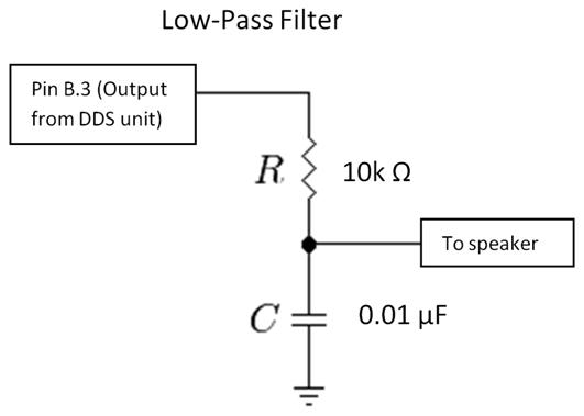
Low-pass filter diagram
Budget:
Item
Vendor
Cost
Notes
Wiimote
Nintendo
$0.00
pre-owned
Custom PC Board
Bruce Land $2.00
last years model
Power Supply
Lab
$5.00
Max233CPP
Maxim
$7.00
RS232 connector
Lab
$1.00
for custom board
AVR ATmega644
Atmel
$8.00
DIP socket
Lab
$1.00
$.50 each
Header socket
Lab
$0.60
$.05 each
Banana clips
Lab $0.00
Circuit board
Lab $1.00
2 inch solder board
Circuit board extra parts
Lab
$0.00
resistors, capacitors, wires
Bluetooth dongle
Iomega
$0.00
previously owned
USB-Serial connector
Lab
$0.00
Audio output device
Lab
$5.00
B/W TV
Inspiron 1300
Dell
$0.00
previously owned
Total
$30.60
Appendix D
Tasks completed by group members:
Sampling chips:
shared
Soldering:
shared
GlovePie scripting:
shared
Visual Basic scripting:
shared
Researching communication methods:
shared
Microcontroller programming:
shared
Debugging:
shared
Lab Report:
shared
Website:
shared
Appendix E
References:
http://www.wiili.org/forum/ - useful forums for example GlovePie scripts
http://www.maxim-ic.com/ - Max233 sampled from here
http://www.atmel.com/ - Atmel ATmega644 sampled from here
http://www.vbforums.com/ - useful forums for example Visual Basic scripts