Voice Tuner and its Effects
Nitin Sitaraman (ns325)
Emmanuel Denloye (eod2)
Introduction
| High Level Design
| Program Design
| Hardware Design
| Results
| Conclusions
| Appendices
| References
Introduction
Sound Bite
Our project implements a tuner that continuously outputs the frequency of an input microphone signal with a high degree of accuracy.
Project Summary
This project's goal is to use a sensitive microphone, computer speakers and a properly designed circuit so that for an input microphone signal a relatively noiseless sinusoidal signal is output to the ADC that is part of the Atmega644 microcontroller. Then with the use of software the correct fundamental frequency from the microphone input may be determined. Because of our interest in music, the tuner was constructed in such a way that it can recognize the frequency of musical notes from A3 (220 Hz) to B5 (987.77 Hz) on the musical scale.
High Level Design
Project Idea Source and Rationale
Despite the various divergent cultures, traditions and languages around the world, the ability to appreciate music seems to be a characteristic present in almost everyone. However though music is thought of as a form of art, musicians spend years perfecting their craft. Proper discipline is appliedwhen regarding pitch, loudness and timbre . The rationale for this project came from Emmanuel whose knowledge of music naturally led to the idea that whistling, singing or playing an instrument off key can be avoided if an accurate tuner is used. Our original goal was to create a tuner that made use of a majority of the knowledge acquired in the ece 476 labs throughout this semester. The original idea was to obtain microphone input from a user attempting to match a note on the musical scale, obtain the pure musical note waveform through the use of Direct Digital Synthesis and a PWM signal, and output both to the black and white TV. The TV would then act similar to an oscilloscope and a user would vary his pitch and intonation in order to cause his own waveform to match the pure note waveform as close as possible. Unfortunately this idea was quickly seen to be implausible as the microphone signal had a significant amount of noise when compared to its PWM generated counterpart. As a result a more practical design that focused on jusr the fundamental frequencies of musical notes was considered.
Background Math
The math involved in this project deals mostly with the use of active filters and amplifiers. A tuner's function is to determine the fundamental frequency of an input signal. To do so both the 60 Hz noise and the higher frequency harmonics need to be rejected while the desired musical note frquencies need to be passed by a bandpass filter. A simple implementation of second order filters to create the necessary bandpass filter can be performed with the use of the Sallen-Key topology.

Figure 1. Generic Sallen Key topology filter
The transfer function for this generic circuit may be determined by using Kirchoff's Current Law twice and rearranging and combining equations. Of more importance is that both a high pass and low pass filter with the Sallen Key topology will have similar transfer functions which result in the same formula for the calculated cutoff frequency of
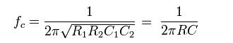
when the resistors both have the same resistance and the capacitors have the same capacitance. With this formula the various resistor and capacitor values can be determined according to the desired cutoff frequency.
Logical Structure
The high level logical structure of our project is shown below.
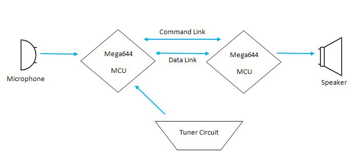
Figure 2. High Level Block Diagram
The block diagram demonstrates the need for two Atmega644 MCUs for our project. One is used for the conventional data transmission and receiving with the computer terminal (UART) while the other is needed to generate the PWM signal at the correct frequency. A discussion regarding the necessity of two MCUs is performed in the program and hardware design section. The Mega644 on the left uses jumpers between ports to create both a bidirectional command link and a bidirectional data link to its counterpart on the right. Meanwhile the right Mega644 provides the PWM output to the external speakers using the DDS algorithm provided in ece 476 lab 2. The microphone inputs an RF signal into the tuner circuit and after appropriate filtering and amplification the signal is fed into the ADC of the left Mega644 so that the frequency may be calculated using the zero crossing method of finding frequency. The result is displayed using UART in addition to the regular menu options.
Relationship of your design to available IEEE, ISO, ANSI, DIN, and other standards
The relevant standards to our project are those established in 1953 by the International Standardizing Organization regarding the setting of musical note pitches to specific frequencies. Additionally the IEEE Code of Ethics is adhered to during the progress of this project.
Program Design
Program Details
The purpose of our project was to create a tuner that outputs the correct frequency given an RF microphone input. While the hardware ensures that a relatively clean signal will be read into the ADC, the software must take this input and return the frequency of the waveform to the terminal. To do this the ADC digitizes the analog wave. Since the wave will have a bias of 2.5 V (which will be seen in the hardware design) and the ADC runs from 0 to 255 for analog 0V to 5V, the RF signal will oscillate around 2.5 V or a digital sample of 255/2 = 127 which can be considered to be ac ground. So to determine the frequency a count variable tick is used to count the number of �zero crossings� for several digital samples and then divided by two to find the frequency since one cycle contains two zero crossings. This method is implemented in lab6.c. Additionally implemented in lab6.c was a PWM signal that when passed through a lowpass filter and connected to the external speakers produced a sinusoidal tone at the correct frequency as determined by Direct Digital Synthesis. For our project we want to be able to output using the PWM and receive and determine the frequencies on the musical scale from A3 (220 Hz) to B5 (987.77 Hz). The hardware tuner circuit will guarantee these frequency values will be in the passband. All that the software needs to do is to once again measure the zero crossings. Using a couple of pushbutton and more logic it is possible to increase and decrease the PWM frequency by one semi-note or by a whole octave as long as the range stays between A3 and B5. However adding a menu that is mostly nonblocking results in a change in the measured frequency, most likely a result of timing issues. After more than 30 hrs it was determined that the PWM ISR and the ISR controlling the increment, decrement and calculated frequency were clashing with each other. A decision was made to move the PWM to a second microcontroller and a bridge from one MCU�s port C to its counterpart�s port C is created with the use of a jumper cable. This is the command link previously mentioned in the logic block diagram where commands for incrementing or decrementing index goes from the left MCU to the right MCU. A diagram of the two MCUs is seen below
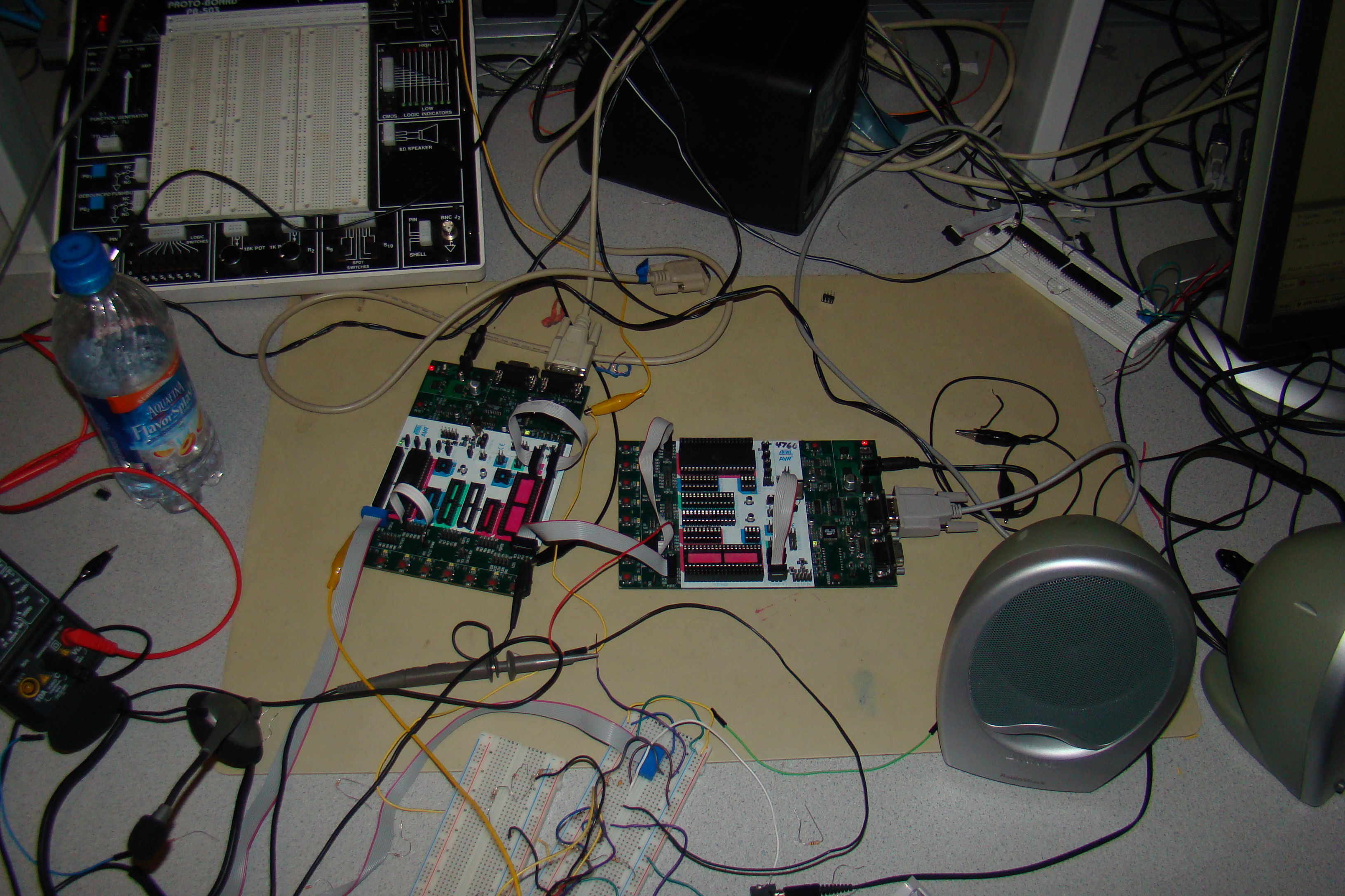
Figure 3. Two MCUs Connected to Tuner Circuit
The right MCU reads in the lower four bits of PORTC while outputting to the upper four bits of PORT C. This makes the command link bidirectional. When the right microcontroller receives whether it needs to add 1, subtract 1 add 12(an octave) or subtract 12 (an octave) it changes the incrementIndex so that the outputted PWM will change its frequency after the low pass filter accordingly.
We have effectively gone from one microcontroller with no state machine driven menu but with a PWM and the ADC generated continuous frequency to two microcontrollers with a state machine menu but where the PWM and ADC are on different microcontrollers. Since the two microcontrollers are connected through parallel ports the timing on both boards and the menu state machine needs to be considered. The menu itself asks the user to enter in numbers to choose whether to enter tune mode of sound effects mode. Sound effects mode was easily to be implemented by changing the PWM signal by distorting it and then sending it through the external speakers. However with the lack of stability present in the tune mode and its menu options of increment frequency, decrement frequency, increment by an octave (if still in range) and decrement by an octave (if still in range) working incorrectly in part because of the novel (to us 476 students at least) use of two boards, sound effects was not implemented. Note also that additional complexity is added to the state machine as every menu display is set so that there is a number the user can enter to go back to the previous menu.
Hardware Design
Hardware Details
The hardware consists primarily of the tuner circuit that filters and amplifies the microphone signal in several stages to produce a well processed signal at the ADC input. By doing so the fundamental frequency found by sampling will be more accurate. The entire tuner circuit is shown below broken up into its component stages. Note that the operational amplifiers LM358 have a 0 V to 3 V voltage swing despite requiring a supply voltage from 0 V to 5 V. In order to avoid negative voltage swings, the GND connection of the LM 358 op amps are connected to Vss = -5 V instead of GND = 0 V. Any one who has experience with circuit elements and a prototboard may build this tuner if they follow the circuit schematic precisley and the directions that follow.
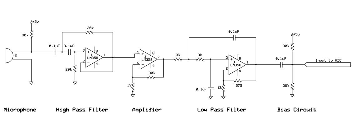
Figure 4. Tuner Circuit
Microphone
The microphone used in this circuit has its positive terminal connected to a supply voltage of 5 V through a resistor and its negative terminal connected to ground. The pull up resistor to Vdd provides a way to determine the voltage response from the microphone input. Additionally the 30 kOhm resistor biases the input to the next stage but this mean voltage is blocked by the capacitive coupling at the input of the high pass filter.
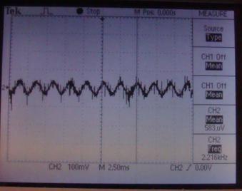
Figure 5. Microphone Input Waveform
High Pass Filter
This is a 2nd order high pass filter in the Sallen Key topology. Note that the feedback loop shorts the output of the operational amplifier to the inverting input. This results in the amplifier producing a unity gain with a Butterworth filter type characteristic in the passband. The high pass filter�s function is to reject the common 60 Hz noise signal from the filtered musical notes which start at 220 Hz. Therefore a cutoff frequency around 160 Hz with equivalent resistors and capacitors allows the use of the cutoff frequency equation displayed above. If all capacitors in the circuit are taken to have a capacitance of 0.1 uF the needed resistance is around 10 kOhms. Further experimentation with the signal generator and PWM signals from the speaker output determined that a better cutoff could be obtained if the resistance value was doubled to 20 kOhms.
Amplifier
This stage of the circuit amplifies the signal that is outputted from the high pass filter. Amplification is done separately from filtering so that voltage saturation may be avoided. The amplifier is in a simple noninverting configuration and therefore provides a positive gain of about 31.
Low Pass Filter
In contrast to its high pass counterpart, this filter attempts to attenuate the higher frequency around and above 1000 Hz. Capacitors of 0.1 uF are used to identify the need for resistors of 3 kOhms. Note unlike the high pass filter, this low pass does not have a unity gain but rather a gain of about 1.3. This small gain implemented through the feedback and inverting input resistors of the low pass filter reduce the noise and instability seen at the ADC input, the output of the tuner circuit.
Bias Circuit
The bias circuit comes at the very end of the signal processing and ac couples the RF signal to exclude any DC bias picked up during amplification or filtering. Then an exact DC bias of 2.5 V is added to since the ADC swings from 0 V to 5 V with a mean voltage of 2.5 V . Without this bias the RF signal will oscillate and produce negative voltages, a result of using supply rails for the op amps of -5 V and 5 V instead of 0 V and 5 V. This DC biased RF signal is input into the ADC to determine its frequency.
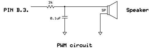
As part of the hardware design a resistor and 0.1 uF capacitor were chosen to filter the PWM into a sinusoidal waveform at the desired frequency. The resulting waveform's frequency could then be determined by the aforementioned tuner circuit. The PWM lowpass filter is shown in the schematics section of the appendices.
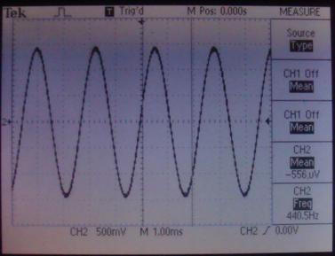
Figure 6. PWM after going through lowpass filter at 440 Hz
Things we have tried but didn�t work
One problem, as explained in the program design, that we couldn�t get fixed relates to the desire to get both the continuous frequency counter and the menu state machine to display on the same UART screen using only one microcontroller. Despite hours of effort and even more hours of help from TAs and even some from Bruce, when the frequency was calculated in conjunction with UART menus then the calculated frequency could vary drastically from the actual frequency output by the PWM through the speaker. Sometimes the frequencies displayed varied widely but mostly when the microphone was picking up signals correctly (the soldering seemed to fail often) then the frequencies output to UART would be precise but not accurate. For example a 440 Hz signal is pushed through the tuner filter, goes through the ADC and output on the UART continuously as about 740 Hz. This difference suggests that more ticks (zeros) are being read in a cycle than should be. If ticks are counted when the menu is note even in tuning mode then higher frequencies than the actual PWM frequency would be expected.Changing state machines, timing rates and printing from blocking to nonblocking were all performed but still the problem couldn't be fixed.
Results
Execution and Accuracy
There is a trade off between execution speed and accuracy. The more accurate the calculated frequency needs to be, the slower the execution of the program. Conversely fast returning frequency values will have less accuracy than a frequency value that returns later in time. It was found that an accuracy of plus or minus 1 Hz can be obtained with an execution time of more than two seconds. It takes two seconds to traverse through all the digital samples obtained through the ADC so two seconds can be thought of as some kind of relaxed lower bound. Another factor that determines how fast the correct frequency is calculated from the digital samples is the distance from the microphone to the source of sound. A microphone held close to the external speaker will have correct calculated frequency readout in less than ten seconds. This occurs because if the receiver is close to the transmitter of a signal the microphone amplitude and the signal to noise ratio is larger and as a result the noise is suppressed easier and the frequency is easily picked during analog to digital conversion.
Usability
The tuner may be used by any number of people in order to sing or whistle at the correct frequency. However note that long time intervals, where many samples are averaged to get the correct frequency, result in the need for the user to hold a musical note for a considerable amount of time. This would be no trouble to those who are experienced singers but those who suffer from shortness of breath or sudden asthma attacks would be advised not to use the tuner to measure their own voice pitch. The high accuracy of the tuner suggests then that the tuner would be of most use in measuring tones that do not require severe human effort to sustain. This may include several types of instruments such as a piano or violin.
Interference with other people's designs (RF interference)
While testing in lab the microphone we used demonstrated that many RF signals could cause distortion to the filtered and amplified waveform that is taken as input into the ADC and from which the frequency is determined. As samples were taken and the zero crossing points recorded the net result of RF interference from an RF source was normally an increase in displayed frequency. Note that with interference the continuous frequency outputs converge to a single value that is not the actual frequency output by the PWM through the speakers. Therefore interference results in no change in precision but a change in accuracy of calculated frequency.
Conclusions
Expectations and Results
For our project it is expected that given a microphone input signal the tuner circuit should produce a processed waveform that is then fed into the ADC. The resulting digital samples are then cycled through and the zero crossing method is used to find the number of zeros (ticks) over the entire set. As mentioned previously each cycle has two zero crossings so dividing tick by two will return the calculated frequency. In addition to this calculated frequency it is expected that the user will be able to manually increment or decrement the current musical note by one note or one octave if the change won�t let it go out of range. Our range is selected from A3 (220 Hz) to B5(987.77 Hz). The design met these expectations but failed to perform when a UART menu was added with its own state machine. The conjunction of a PWM, continuous frequency printing and a UART state machine was what forced us to start beginning to use two microcontrollers at the advice of the TAs after spending tens of hours on the single microprocessor version. Next time we'd probably still stick to the single microprocessor version and try to figure out how to fix it since we now have learned that using two microcontrollers causes more problems than it solves regardless of what the TAs say.
Applicable Standards
The only standards to be considered in our project were those defining the exact frequency of each musical note on our scale. The full musical notes scale is linked to in the references section.
Intellectual Property Considerations
There was a certain amount of code reuse during this project. Code was taken from the 476 sample code and examples given throughout the semester and used as a starting point to perform certain functions that satisfied our project. For example the DDS code from Lab 2 was of special use when trying to output a pulse at the correct frequency. In addition to taking class code, which we may classify as �public� as it was accessible to all students, the only other code reused was that which was written by us during our own labs. The angle array used in the lab 4 was modified and then reused as the incrementIndex that determined the frequency of the PWM to be output to the low pass filter and then to the external speakers. No design was reverse engineered so there were no patent or trademark issues for our project. All sample parts needed were in the lab which meant that a non-disclosure did not need to be signed. On the subject of patent and publishing opportunities we acknowledge that others may have created their own tuners but there is no reason their topologies would be the same as ours. It would be interesting if several different topologies for tuners were rigorously compared and the resulting speed and accuracy reported for each different configuration. In such a case there would be a publishing opportunity for our project. If we came up with some radical new process through which to measure frequency then the process may be able to be patented. However it would be rare for such an opportunity to arise.
Ethical Considerations
Throughout the course of the project we adhered to the IEEE Code of Ethics. Many times in our project it became necessary to increase the volume of the frequency tone to a very painful level for those around us, especially when using our first microphone that had very little sensitivity. We both accepted the responsibility to keep such a disruptive noise to a minimum. Many times we would increase the volume rapidly, freeze the scope , decrease the volume, and then read the frequency off the scope using cursors. Doing so saved those who worked in the lab around us from a lot of headaches from repeated high frequency pulses. The code was also followed in regards to the presentation and discussion of project data for this final project. No values have been fabricated and any code that has been copied from other sources has been mentioned on the project web page. This project has been a learning experience for both of us and we have welcomed the sharing and listening that occurs between project groups and TAs in lab. We have taken advice from those who are more experienced and implemented the appropriate changes in our design.
Legal considerations
Our project has a transmitter (external speakers) and therefore FCC regulations must be considered. Legal consequences do not pose a significant issue as the 1 kHz frequency set as the upper bound of our transmitter is well within the range of frequencies the FCC has allocated to no official use.
Appendices
Commented program listing
lab.c
lab6PWM.c
Schematics
Cost Details
| Part Name |
Source |
Quantity |
Price |
Total Item Price |
| Atmega644 MCU |
476 Lab |
2 |
$8 |
$16 |
| STK |
476 Lab |
2 |
$15 |
$30 |
| White board |
476 Lab |
2 |
$6 |
$12 |
| microphone |
Friend |
1 |
Free |
$0 |
| 2 pin flat jumper cables |
476 Lab |
1 |
$1 |
$1 |
| Power supply |
476 Lab |
2 |
$5 |
$10 |
| Jumper cables |
476 Lab |
4 |
$1 |
$4 |
| LM358 amplifier |
476 Lab |
4 |
Free |
$0 |
| Speakers |
476 Lab |
1 |
Free |
$0 |
| Total |
|
|
|
$73 |
Task Distribution
- Initial Sallen Key Filter Design: Emmanuel
- Building LP and HP filters: Emmanuel
- Implement PWM: Both
- Implement increment/decrement frequencies: Nitin
- Testing varying frequencies: Both
- Constructing UART Menu: Both
- Testing UART Menu: Both
- Pass PWM frequencies from one board to another: Both
- Pass data from one board to another: Emmanuel
- Lab report source text: Nitin
- Web page design: Nitin
References
Data sheets
LM358 Op amp
Mega644
Background sites/papers
Second Order Filter section demo
Sallen Key Topology
Musical Notes Scale

