Heliostat Skylight
ECE 476 Final Project By: Yinan Tang and Nana Wu
Introduction
With the increasing awareness of sustainable and green building, more and more people are concerned with
the efficiency of energy use at home and at work. For our ECE 476 Final Project, we developed a microcontroller-based, interior illumination system - The Heliostat Skylight. By reflecting light that would otherwise be lost, the Heliostat Skylight will enable users to conserve energy by producing increased light levels and for a longer duration than normally possible. Although our project concept is simple, we hope that by allowing people to use a little bit less electricity every day, over time, this will accumulate to be an enormous benefit for society.

High Level Design
A. Background
In our design, the Heliostat Skylight can be in two operation modes:
B. Background Math
As shown in the schematic, assume the incident angle of sunlight is theta, the included angle of reflective panel and the skylight is beta, then the effective illumination level is proportional to A in conventional skylight, and B in the heliostat skylight.
C. Design Concept A. Setup
A diagram of the Heliostat Skylight is shown below:
B. Hardware
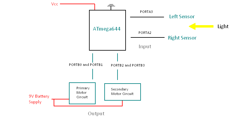
The microcontroller that we used for this project is the Atmel ATmega644 [1]. The following diagram below shows the hardware layout for the heliostat:
C. Software
The software of the heliostat skylight is designed to work in real world situation. In ideal situation, it turns 180 degrees everyday to trace the sun. For testing purpose, we decide to scale down the duration of a day and use 60 second instead of 24 hours as one “day”. The final program can be divided up into 2 major modules: motor control and ADC sampling of the 2 sensors; 3 major operating modes: off mode, tracking mode and cloudy mode. All the transitions between different operating modes are fully automatic and the conditions for transitions are determined during testing.
ADMUX = (1<<ADLAR) | (1<<MUX1)
if(RLflag==1) sensorRight = ADCH;
if (i<=30) databackup[i] = 6*i
During final testing, the primary motor seemed to wear out and turned rather slowly. Despite this, the heliostat can find the position of the sun accurately in most of the testing cases. In some rare situations, it seems that the heliostat cannot find the balance position, in which two sensors give similar voltage outputs, so the heliostat kept turning left and right iteratively. This problem can be solved by either making modifications in software or building a better light cover for the sensors. A. Analysis
Overall, we are very pleased with the results of our project. We managed to complete the design that we planned in the proposal and learned alot in the process - especially about driving motors and mechanical design. The most difficult process was building the structure - mainly due to issues of accessing the machine shop during this final project period. In retrospect, we definitely would have started this part sooner.
B. Intellectual Property Considerations
The inspiration for this project came from two sources:
C. Ethical Considerations
Throughout the project, we vigorously upheld the IEEE Code of Ethics, to ensure our safety and those around us. We built most of the structure in the safe confines of the machine shop, to make sure that we imposed no danger to those around us during the construction period. Throughout the project, we consulted with Prof Bruce Land and the various TAs. Their comments and advice have aided us significantly. We have made sure that all the ideas that were taken from external sources were received proper credit for their help. There were no sources of conflict during the course of this project. Had we encountered any forms of bribery, we would have not accepted them. We have never discriminated against anyone based on any factors including race, religion, gender, disability, age, or national origin. All of the circuit descriptions stated in this report are true to the fullest extent of our knowledge. In addition to increasing the efficiency of sunlight use, protecting the user’s health was also an important concern. It is important to make sure that UV radiation is not too intense, which is why Sun Protection Mode is so important. We have learned a lot from this final project, from learning how to build complicated structures, to using sensors effectively and soldering hardware.
A. Budget
B. Tasks
Yinan Tang: Skylight structure design and construction, Circuit design, Software coding, Testing and Debugging, Report C. Source Code D. References
1. Sun Tracking is used when the sun is low in the horizon and early and late in the day, throughout the day during winter months and all year long in northern lattitudes. By aligning to the position of the sun, the Heliostat Skylight reflects light down into the space which would otherwise be lost due to the low incident angle.
![]()
2. Sun Protection comes in handy in hot summer days when there is excessive sunlight. Diffusive reflective material used at the back of each reflector panel can block the harshest rays of the sun and maintains a soft indoor lighting condition. This reduces heat load and glare, and enhances the use of natural daylight, thereby reducing the operating costs of the building.


For theta < beta,
A=9"sin (theta) and B=9"sin(theta)+4sin(beta-theta).
For theta > beta,
A=9"sin (theta) and B=9"sin(theta)-9sin(theta-beta).
In our design, we chose beta to be 60 degrees. We can quantitatively evaluate the performance of conventional skylight verses our heliostat skylight by comparing the value of A and B. Tracking the sun’s movement generates up to more than 2 times the light levels in the space below. In the summer, when the sun is directly overhead, the reflective panel actually lower light level and solar heat gain 50%.
Incident Angle Theta
Conventional Skylight
Illumination Level (A)Heliostat Skylight
llumination Level (B)B/A
15 2.33 5.16 221.5%
30 4.5 6.5 144.4%
45 6.36 7.40 116.4%
60 7.79 7.79 100%
75 8.69 6.36 73%
90 9 4.5 50%
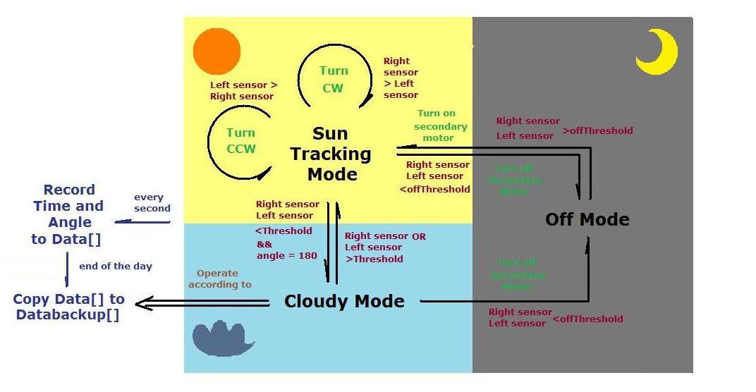 At the beginning of the day, when the sensor detects light, the heliostat enters Sun Tracking Mode. The secondary motor hoists the mirrors upwards at a tilt of 60 degrees and motor angle data is recorded, given that the heliostat is not in Cloudy Mode.
It then checks which sensor has a higher light level, and rotates accordingly. If the sensors are both underneath the cloudymode-threshold, the Cloudy Mode state is entered. In this state, the heliostat turns from its last recorded position to the 180 degree position, back and forth, until a light source is detected from the sensors again. Note that if the heliostat goes into Cloudy Mode at the initialization, it operates from the last recorded position of the backed up data from the day before.
The heliostat turns off using the secondary motor, if it is under the off-threshold.
Program/Hardware
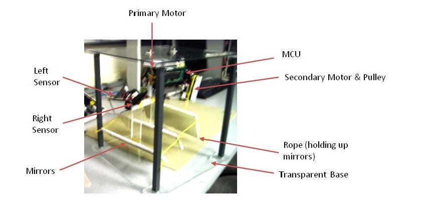
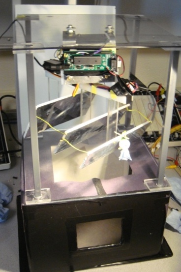
A closeup of each component is shown below:
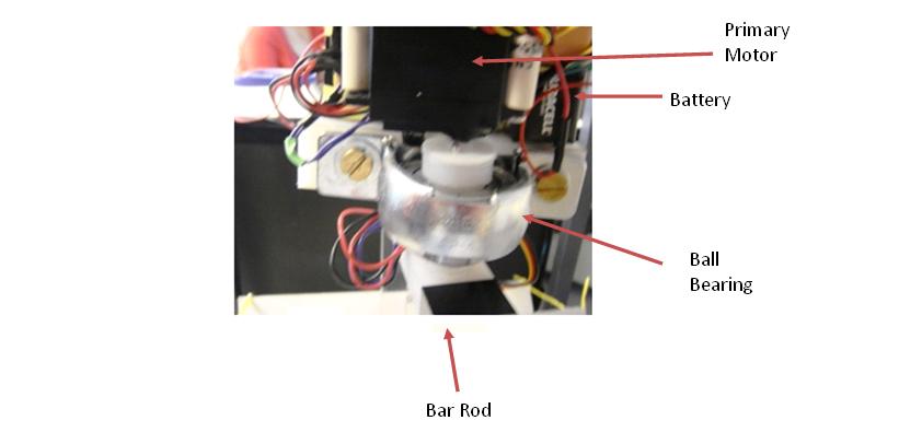
The heliostat consists of a primary motor attached to a ball bearing that turns a bar rod. The sensors are attached on one end of the bar rod. A clearer picture is shown below.
This primary motor controls the rotation of the heliostat. Depending on the readings of the two sensors, the heliostat will know which direction to turn. If the right light level is greater, it will turn in that direction - and the opposite is true for the reverse case. Each sensor has a light cover on top so that it only senses sunlight coming directly towards it. The mirrors are hoisted up (in the on-state) and down (in the off-state) by the secondary motor using a semi-pulley system. The base of the structure is transparent to allow light to shine down into the room below:
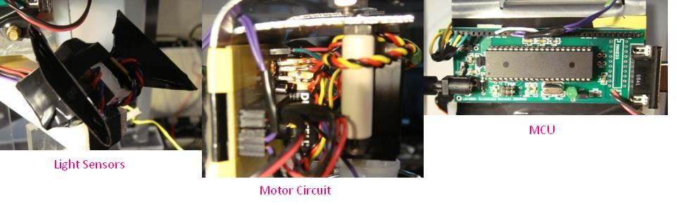
 The sensor used was the TAOS TSL13S Light to Voltage Converter [2] . Originally we were considering using another sensor by the same manufacturer. However after ordering both and doing some testing - we realized that the TSL13S gave a bigger output voltage range. This output is fed into the MCU, which is processed to control the motor direction.
The primary motor of the heliostat is the HS-475HB manufatured by Hitec RCD Inc [3]. The secondary motor we used is the HS-322HB, also manufatured by Hitec RCD Inc [4]. The circuit we used for both motors is shown below:
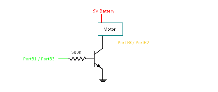
The BJT acts as a switch for the motor, while Ports B0 and B2 contain the motor control signal. A more detailed description of motor control is described in the software section below.
ADC Sampling
In order to drive our skylight to face the sun, 2 sensor outputs need to be sampled and compared continuously. The ADC condition was initialized by setting the following:
ADCSRA = (1<ADEN) | ((1<ADSC) + 7)
Then in the Timer1 compare match ISR, the internal ADC, specifically ADC2 and ADC3, in Mega644 was switched repeatedly to sample the two sensor inputs. The TIMER1_COMPA_vect was executed every 1mSec, thus we was able to obtain updated information from sensor every 2mSec, which is good enough for sun tracking purpose. Moreover, because the rate of ADC is 125,000Hz, so 1mSec is definitely enough time for the conversion to complete. The following code was included in TIMER1_COMPA_vect to read the two sensor outputs.
else sensorLeft = ADCH;
ADCSRA |= (1<<ADSC) ;
RLflag = !RLflag;
if(RLflag==1) ADMUX = ADMUX - 1;
else ADMUX = ADMUX + 1;
Servomotor control
Controlling the servo motor needed great precision. The servo requires an input pulse that has period of 20ms, the valid range of pulse width are roughly from 0.5ms to 2.5ms (0.5ms corresponds to 0 degree and 2.5ms corresponds to 180 degrees). To accurately implement the pulse, we generated a 0.05mSec time base using the timer0 compare match ISR. So we were able to turning the motor as precise as 180/((2.5ms-0.5ms)/0.05m)= 4.5degrees.
In main function, the sensor outputs were checked every second, the ADC results of the right and left sensors then determine the motion of the motor. We have five different conditions, defined by variable direction, for the 2 sensor inputs. When both sensor inputs are less than an offThreshold, the skylight will be turned off automatically because of the low external sunlight level. Ideally, this will only happen during night time.
Direction 3 (refer to code) means that the system does not know where the sun is, and this is caused by ambiguous sunlight levels sensed by both sensors. This condition may happen on cloudy days, when sunlight is moderate and lacks directional information. The last three conditions are corresponds to turn right (direction =1), turn left(direction=2) and no turn(direction =0).
Though our testing “day” is relatively short (60s), considering the real world constrains, we decide to turn off power to motor after being used. From datasheet of the motor as well as during testing, we found that 1 second is long enough for the motor to turn a significant angle. Everytime when the power of the motor is switched on, it will be automatically switched off after 1 second. This function should be useful when the skylight is actually operating 24/7, as it not only saves electric power but also preserves the motor's life.
Sun Tracking and Cloudy Mode
Once the heliostat is turned on, it goes directly into Sun Tracking mode, in which the motor is controlled by the most updated sensor outputs. The primary motor turns on when direction is not equal to 0 (facing the sun) or 4 (night time). When direction equals to 1 and 2, the motor turns clockwise or counter clockwise respectively. When direction equals to 3, no direction information is obtained from sensor, the heliostat will turn clockwise to find the position of the sun. If no directional information is found even when it turns all the way to 180 degrees, then heliostat leaves Sun Tracking mode and enters cloudy mode.
The Cloudy Mode is specifically designed for real world situations when sunlight is ambiguous. In Cloudy Mode, the heliostat is operated using pre-stored motor angle information, which is a good estimation for the position of the sun. Sensor output is also checked at 1Hz in Cloudy Mode. Once direction is found to no longer be equal to 3, the system will quit Cloudy Mode and operate under Sun Tracking mode again. Smart transitioning between these two operating modes is fully automatic and is designed to ensure high illumination efficiency.
Data Recording
All the operating information, specifically time and angle, is recorded once a second. During operation, the information is stored temporarily in an array data[]. At the end of a day, information in data[] will be transferred into databackup[] and save for late use. However, we decided to transfer data to databackup[] only when cloudy mode was not entered during the daytime, in which case, the movement of the skylight should be regular and steady in real situations.
In initialization, we give certain initial value to databackup[]. Because we assume the first 30 seconds as day time while the rest is night, and the movement of the sun is at constant speed, we set
else databackup[i] = 180
Results
When we tested it a week ago, the heliostat could find the direction of the sun within 1 or 2 seconds. However, during the final testing week, the speed of execution was greatly influenced by the wearing issue, while all the control signals are correct. It seems to experience more frictional force when turning clockwise than counter clockwise.
Below shows the heliostat in operation during the on and off states:
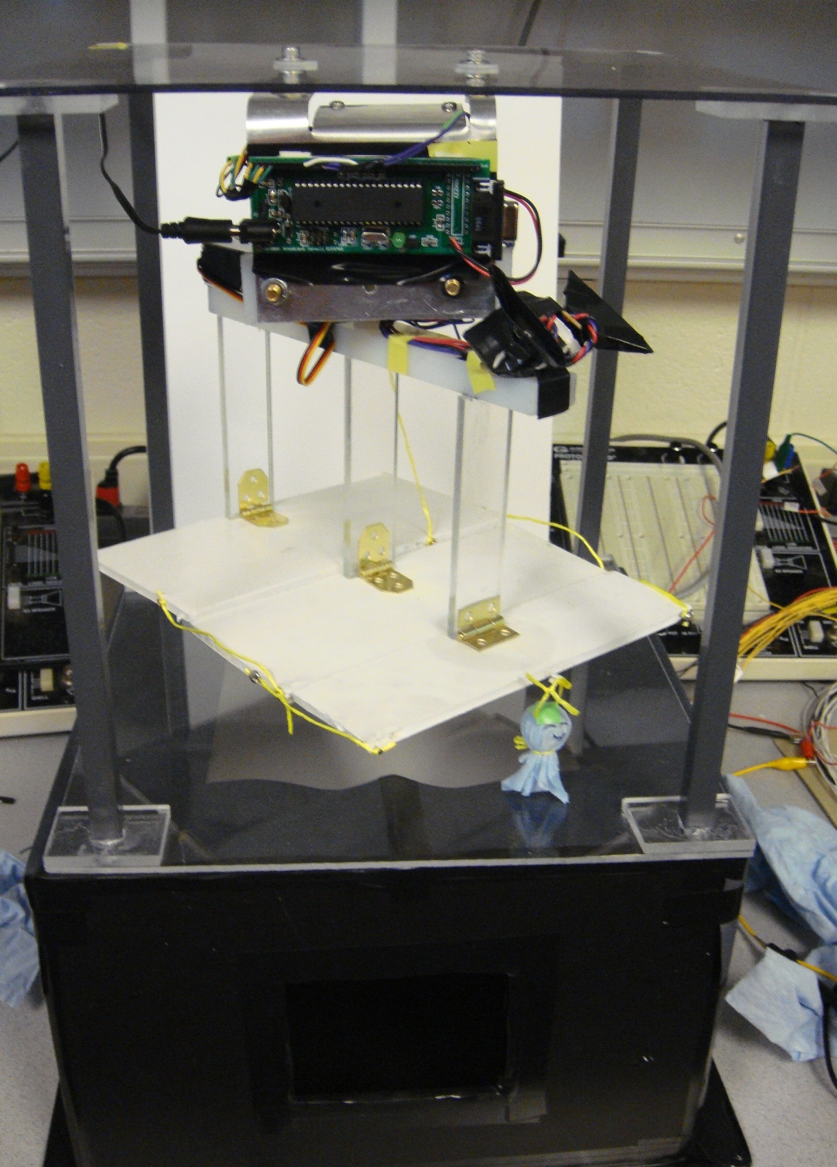
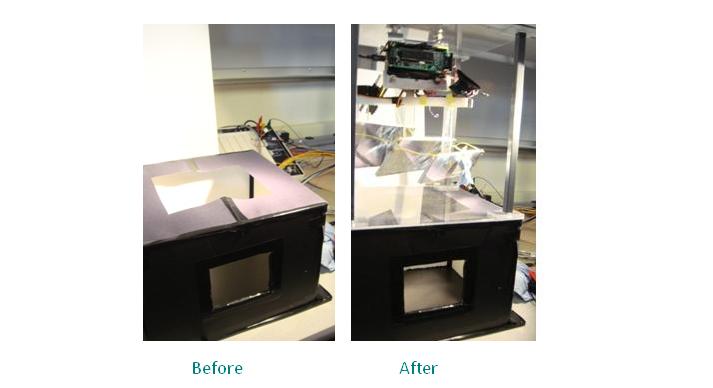
For testing purposes, we built a model house to see the changes in its internal illumination level with and without the heliostat (see below). As show in the first picture, before putting the heliostat on, the internal lighting condition is bad and the most of the floor region is dim. After putting the heliostat on, the lighting condition improved significantly.
Conclusions
If time, resources, and the budget limit were not an issue, we would have bought a more powerful motor. implemented a user interface using wireless transmitters and receivers. The user could then turn the heliostat on and off inside the house at will, and possibly receive information about the status of the heliostat - instead of having the heliostat constantly be in automode. This could also have conserved energy. Keeping up with the green theme of our project, another improvement that could have been made would be to power the entire heliostat using solar energy. Obviously this would have required more testing outside the lab for the photovoltaic cells.
It would have been interesting to see how our model heliostat operated in the natural daylight. However this is alittle implausible for the class because Bruce would have needed to wait hours for the heliostat to move during the demo.
- Solar Tracking Skylights , developed by Solar Tracking Skylight Inc in Chicago, consists of highly reflective mirror panels that follow the sun's position in the sky. This solar tracking and reflective optical system is designed to capture the maximum amount of sunlight [5]
- Sun Protection Louvers , manufactured by Colt, provides effective shading during the peak hours of the day, creating attractive diffused light within the internal space [6]
The heliostat was built using software that we wrote and hardware that which we designed. Although this project is influenced by commercially available products, the purpose of our project was to learn how to develop a heliostat - which we accomplished. We have no desire to patent the final result.
Appendix
Part
Quantity
Unit Cost
Total Cost
TSL12S Light-to-Voltage Converter 2 $1.26 $2.52
HS-475HB Standard Servo 1 $16.85 $16.85
HS-422 Standard Servo 1 $12.99 $12.99
Ball Bearing 1 $9.54 $9.54
Materials (Sheet Metal, Plastic, Foam Board) $25.00 $25.00
Atmel Mega644 1 Sampled $0.00
9V Battery 1 Previously Owned $0.00
LED, BJT, wires, resistors Lab Supply $0.00
header socket/plug 80 $0.05 $4.00
Total $70.9
Nana Wu: Circuit design, Software coding, Testing and Debugging, Report, Webpage creation
[2] Link to TAOS TSL13S datasheet
[3] Link to HS-475 Motor Description
[4] Link to HS-322HD Motor Description
[5] http://www.solar-track.com
[6] http://www.shadinglouvres.com