
Introduction
For our final project, we built a surface electromyograph to collect and analyze data on muscle activity, which supports two channels, implements wireless transmission, and can be worn as mobile unit. Surface electromyography (EMG) is a noninvasive technique to record the activation signals of muscles when they are mechanically active. This signal is very small compared to the 60 Hz signal which appears on the human body from power systems. Wireless was employed to safely isolate the human body from 120V power supply and ground. The system takes data from a small, mobile transmission unit and outputs and stores data into Matlab for future analysis.
High Level Design
Rationale
In bioinstrumentation, an electromyograph is used to monitor muscle activity and diagnose muscular diseases. The EMG works by measuring the electricity generated by the many myoelectric action potentials that change when a muscle is active. These action potentials can then be recorded, amplified, and sent to a computer for processing. We wished to make a device that could monitor muscle activity remotely without impeding the users movements. This would allow one to see how often they are using a exerting a muscle during an activity. Also, those with jobs that require high amounts of physical exertion, such as automobile union workers, can use the device for ergonomics studies. This project allowed us to use various skills acquired in previous courses and this one, in order to build an interesting, complex, and useful instrument.
Existing Products
The technique of electromyography has existed for centuries. There are products that implement wireless EMG that exist today, but no patents, copyrights, or trademarks to prevent us from producing our own version.
Project Implementation
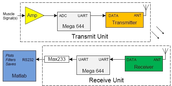
Figure 1: High Level Implementation
The project is composed of two main parts: the transmit side and receive side, as illustrated above. The transmit unit consists of EMG electrodes, amplifier stage, a microcontroller, and the transmitter. One electrode is placed on the muscle of interest, typically the bicep, and the other on the opposite side, typically the tricep. The voltage difference between these two is amplified with a differential amplifier, arranged for a high gain. The output of the differential amplifier is sampled on the transmit unit. The transmitter places groups of samples into packets, which are broadcasted wirelessly on 433 MHz. The transmitter is powered by itself using a 9V battery.
The receiving unit consists of the receiver, a microcontroller, and computer. The receiver receives the packets of information consisting of samples, high pass filters the data, and relays the information onto Matlab. In Matlab, a comprehensive user interface was created for recording, accessing, filtering and analyzing of the obtained data.
Tradeoffs
There were several opportunities for hardware and software tradeoff. One example is between the front-end amplifier and software gain. The advantage of using more hardware gain is the increase in the ratio between the signal and quantization error. Software gain not only amplifies the wanted signal, but also amplifies the quantization error already obtained from the analog to digital converter. However, using too much hardware gain can potentially max out the range of the amplifier and cause clipping. We chose a fixed hardware gain of 150 on the differential amplifier. Software gain can be achieved by the user by simply zooming in on the graph in Matlab.
Another opportunity for tradeoff is the implementation of a high pass filter on the signal. A high pass filter is needed in order to filter out the motion artifact, caused by muscle movement and positioning, and not actual firing of the motor unit action potentials. A hardware implementation would require the use inductors and capacitors on the output of the amplifier, before the MCU sampled the signal. The advantage of this is that the filter is instantaneous and requires no processing power from the CPU. However, finding appropriate inductor and capacitors is very difficult, and inaccuracies affect the frequency response significantly. A software implementation was instead used.
Program/Hardware Design
Transmit Unit
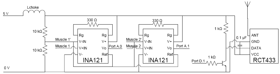
The transmitting unit is composed of the amplifier, microcontroller, and transmitter, as pictured.
Amplifier
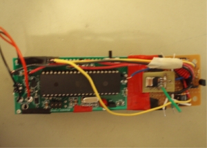
Figure 2 Transmit Unit
The differential signal from the bicep is only on the order of 10 mV when fully flexed, so a high gain amplifier is needed. The INA121PA was chosen, since it can provide very high, linear gain, which is easily selected with an external resistor. The output is also biased with a reference voltage.

The body serves as an antenna for receiving RF signals as well as 60 Hz signal from power systems, so the common mode rejection ratio (CMRR) of the differential amplifier is of the utmost importance. The CMRR of the INA121 is 106 dB, which is very high.
The full hardware schematic is shown in Appendix B. The positive input was connected to an electrode on the desired muscle, typically a bicep. The negative input to the differential amplifier was connected to VDD/2 in order to serve as a reference voltage on the users body, and was connected to an electrode placed on the opposite of the monitored muscle, typically the corresponding tricep. A second pair of electrodes can be optionally connected as well into the second differential amplifier.
Transmitting MCU
A prototype board, powered by a single 9V battery, was built for the microcontroller, as pictured on the right. Items such as the RS232 serial connector and Max 233 were not placed on the board, since its communication is done completely through the transmitter. The output from the differential amplifier was connected to the A0 pin on the Analog to Digital Converter (ADC). AREF was connected to VDD on the prototype board. The quantization error, as previously discussed is  Compared to a 5mV signal, which would be amplified to 1.5 V, the error is approximately 1.30% of the signal.
The system is limited by baud rate of the transmitter and receiver. The transmitter samples at 800 Hz, and averages every 8 samples into one large "supersample". Taking 8 samples rather than one reduces the noise per sample sent by a factor of √8 = 2.83.
For two channels, the system still samples at 800 samples/second, but only 400 samples/second per channel. However, the data transmitted per channel is also halved, so the noise reduction remains the same.
Two channels are implemented using a switch attached on Ports C.1, C.0, and ground. Port C.1 is pulled high, so when the switch is to the left, C.0 is pulled high as well and the transmitter sends data from two channels. When the switch is to the right, C.0 is pulled low the transmitter sends data from one channel.
Transmitter
The transmitter and receiver used are the RCT-433-AS, and RCR-433-RP modules, as provided in lab. The transmitter has four pins: VCC, ground, data and antenna. The full schematic can be seen in Appendix B.
Power into the chip comes through from the prototype boards 5 V regulator and ground. This has no connection to 120V power supply. VCC comes through a self-wound inductor on the order of nano-Henrys to filter out any bouncing in the power supply to the transmitter.
On the transmitter, Data input is connected from the D1 pin into a common emitter amplifier, which is connected to the transmitter, as shown in Appendix B. This is done to make the data input on the transmitter a rail to rail CMOS input. The transmitter transmits the data using On Off Keying (OOK), which means the antenna produces a 433 MHz continuous wave (CW) signal when the data input is high, and nothing when the input is low.
Ideally, the transmitting antenna would be at least λ/4, calculated below.

However, the antenna used, as seen in the picture, is much shorter, at approximately 2cm. This was done so that the user can use wear unit as a mobile device.
The transmission protocol is borrowed and modified from Wireless Transmit and Receive project. The transmitter and receiver run at a speed of 2400 baud. The protocol for a packet is as follows, and will be elaborated on in the next section.
| Byte Number | Definition |
|---|---|
| 0 | Initiating Sequence |
| 1 | Starting Character |
| 2 | Number of Channels |
| 3 | Number of bytes n |
| 4 | Packet Number |
| Remaining 2n bytes | Payload of n bytes |
Figure 3 Transmit Protocol
To transmit the data, each byte is separated into its upper and lower nibble. Each nibble is then encoded by an 8-bit sequence consisting of equal number of ones and zeroes. This is done because the receiver has an internal gain that tries to differentiate between ones and zeroes. If the receiving unit sits long enough without a signal, the gain will increase such that the receiver interprets ones and zeroes from Gaussian white noise. For this reason, it is important to keep the number of ones and zeroes sent to be as close as possible.
Choosing the payload consists of tradeoffs. The bigger the payload, the less time is wasted on overhead, which increases the data transmitted. However, synchronization between the transmitter and receiver will also occur less often, leading to increased possibility for dropped packets and loss of data. A payload of 30 bytes per packet was chosen. 3.33 packets are sent per second, so the receiver receives samples at 100 samples/second. By Nyquist sampling theorem, this is fast enough to 50 Hz signals from the muscle. When transmitting two channels, 50 samples per second are sent for each channel, fast enough for 25 Hz signals from the muscle.
Receive Unit
The receiving unit is composed of the receiver and a microcontroller.
Receiver
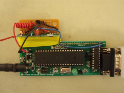
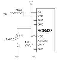
Figure 4 Receive Unit
The receiver similarly has four connections: ground, VCC, data output, and an antenna. Data output is CMOS compatible, and optimally, is the same as the data input given into the transmitter. Data output is connected through a common emitter amplifier into the D0 pin on the receiving MCU.
Receiving MCU
Another prototype board was built for the receiving MCU, this one with the Max 233 and RS232 serial connector. The MCU decodes the received data and interprets each byte from the table above accordingly.
Bytes #0 and #1, which have values of 170 and 202, signal the beginning of a packet. The receiving MCU then knows that byte #2 indicates the number of channels that is being transmitted. If this value is not a 1 or a 2, then it is most likely an unwanted packet from another source using the same protocol, and the data will be ignored. Byte #3 indicates how large the payload is, so that the MCU knows the ending of a packet. Byte #4 indicates the packet number, which the transmitter sends with values of 0 incrementing to 255. If a packet is skipped, then the receiver will know from a discontinuity in the packet number. The rest of the packet consists of payload. With one channel, the payload completely consists of data from that one channel. With two channels, the successive bytes are staggered with channel one and channel two data. The receiver can also filter out the packets of other people that are transmitting with our protocol by checking the transmit ID and the packet length. If another persons packet was detected, it will immediately drop it and try to get another packet. Our packet sizes are fixed and we only use two transmit Ids so this scheme will filter out most unwanted packets. Dropped packets are calculated by keeping track of the number of the last successful packet and subtracting the current packet from that number.
The receiver microcontroller talks to Matlab through the serial connection using the RS232 protocol. The code we use is borrowed from Bruce UART code with the receiver side and formatting stripped out. This is because the data we send to Matlab is a raw bytestream and as the receive pin of the MCU is used by our RF link, there is no way to send commands back to the MCU except through the transmitter unit. The microcontroller automatically tells Matlab how many channels are being used. The MCU sends a 255, followed by the number of channels being sent. This way, the user only has to flip the switch on the transmitting unit, and does not need to tell Matlab how many channels are incoming. When Matlab detects a dropped packet, it simply pads the missing data with the value of the last successful data point. This prevents the filters from misinterpreting missing data as high frequency shifts. After too many dropped packets, Matlab will cancel the connection assuming that either the connection is too bad, or that the transmitting MCU has dropped out.
Matlab
Matlab stores the data and performs signal processing. Below, raw unfiltered data, high pass filtered data, rectified data, and time average rectified data are shown.
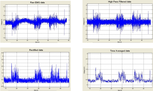
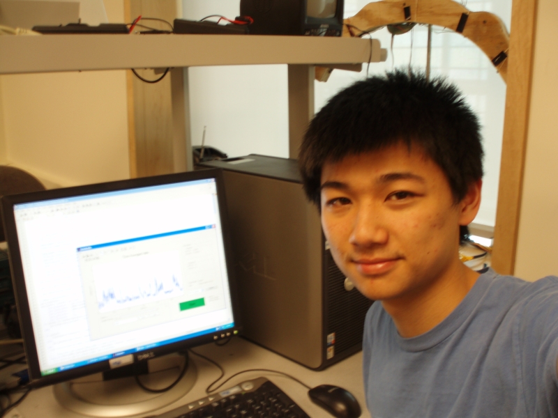
Figure 5 Raw Data, High Pass Filtered, Rectified, Time Average Rectified or "Envelope" from Yuchens right bicep for a 30 second period.
High Pass Filtering
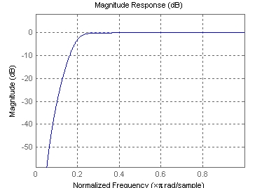
Matlab runs a discrete 5th order high-pass filter with a cutoff frequency of 20Hz to filter out motion artifact. The filter was implemented using the following formula, with constants generated by Matlabs butter function.

The frequency response is shown below. The high-pass filter is used to filter out low frequency signals caused by positioning of the muscle, rather than the actual action potentials firing. There were several reasons we chose to make the filter in Matlab rather than the MCU. First, the computer has much higher processing power, and thus can create a filter with a higher cutoff rate. Also, the computer uses floating point, and can get better precision than the MCU. The frequency response is shown in the figure below.
Rectified Signal & Time Average Rectified
The rectified signal is simply the absolute value of the high pass filtered signal. This starts to develop an noticeable envelope for the signal. A time average of the rectified signal can also be taken, which shows a more distinct, cleaner envelope. However, frequency information is lost after this processing.
GUI
We created Graphical User Interface (GUI) for an easy interface between the user and the EMG. The GUI can collect raw EMG data and save the data in real time. After recording the data, it can load old data, and seamlessly switch between viewing the raw data, high pass filtered data, and envelope of these data sets without losing the raw data. The GUI also saves time stamps of each data collection and when multiple data sets are saved to the same file. Using these it can load in a data set containing all data collection sessions spaced at the appropriate intervals.
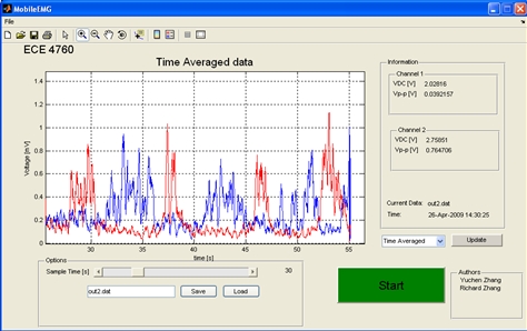
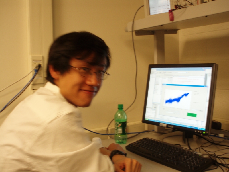
Figure 7 Graphical User Interface - displaying envelope from Yuchens right arm (red) and Richards left arm (blue)
Results
As explained in this report, our EMG gives 100 noise-reduced samples per second for one channel, fast enough to see some of the frequency spectrum of an EMG, and certainly fast enough to monitor the extent to which a muscle is being used. The GUI created allows easy user interface with our project, and the data is saved so that analysis is not limited to the filters provided in the GUI.
In testing, we have typically used our biceps as the muscle of interest, since the bicep is easy to move and flex. The device also works on the quadriceps and is functional, though more difficult to test.
Our project transmits and receives at the 433 MHz, so we can both interfere with and be interfered from other groups. However, through proper protocols, each group can filter out packets which are not their own.
Because the project consists of taking a biological signal from a human body, the safety concerns are apparent. The transmitting unit is completely separate from 120V power supply and ground.
The EMG works best on large muscles, such as the biceps and quadriceps. Anyone who has use of those muscles can use the EMG to monitor those muscles.
Conclusion
For the most part, our design met the goals which we set out to achieve in our project proposal. The EMG is able to monitor the muscle activity of the user while performing some physical activity. The transmit unit is small and light enough that it can be conveniently worn without inhibiting movement. A short antenna, though with decreased range, is able to transmit far enough that the user can perform activities remotely within a range of 15 meters. Data is stored and analyzed on the computer.
An improvement that can be made is modifying the printed circuit board (PCB) made by Bruce for the microcontroller by incorporating the differential amplifier and transmit unit right and not incorporating pins for ports which we did not use. This would result in a smaller, compact, singular unit. Also, an improvement would also to use a transmit/receive pair with higher throughput, perhaps in the Zigbee 2.4 GHz bandwidth. This was not implemented in this project, as we could not afford modules for this frequency band on this budget. Also, a PCB would allow us to use a PCB antenna, which would give increased range.
Our design conformed to all safety standards, and samples at a high enough rate to see a significant portion of where muscle activity falls on the frequency spectrum. We did reuse code and modify code for the protocol of the transmit/receive pair, as reference in Appendix. Because other industrial devices exist which implement wireless EMG, there are likely no publishing or patent opportunities. However, perhaps with future improvements and incorporations of other types of data, such as an electrocardiogram, accelerometer, and pedometer, we may be able to build a unique instrumentation device with better opportunities and marketability.
Intellectual Property
We did use modified code from a previous project regarding wireless transmission protocol, and have cited that project in the Appendix. We have also used code from Bruce regarding the UART. We are not reverse engineering any design, and there are no trademark or copyright issues. We did not sign any nondisclosure agreements when receiving our samples. As stated above, we will not pursue publishing or patent opportunities regarding this specific project, but may expand and add to this project in the future.
Legal
Our project falls within scientific and medical uses, in the ISM band of 433.05 MHz up to 434.79 MHz. The power of our transmitter is also low, and the transmitting antenna is very short, so the signal does not reach much farther than outside the room. We are also not violating any copyrights, trademarks, or patents by building our project.
Ethics
In working on this project, we held ourselves to a high ethical standard and met the guidelines provided by the IEEE Code of Ethics.
There were some safety concerns when developing our project, but we were very careful in avoiding any risk of injury. Before testing on any human, including ourselves, we asked the professor to verify that our design was indeed safe. Before allowing any of our classmates to test, we demonstrated and explained the safety concern inherent in the project and how we alleviated those concerns. Our project does not draw significant current or have any harmful effects on the environment or human body. Also, we do not claim our project to be a medical device and it should not be used as such.
We also made sure to turn off our transmitter when it was not in use, in order to not interfere with other groups in the lab on the same frequency.
There were no conflicts of interest when making our project. We had no goal or incentive of monetary gain, and encountered no bribery. Our interest was to learn and develop our engineering skills, which is consistent with the goals of this class.
This report is an accurate representation of our body of work. The descriptions of our hardware, software, procedure, and methods correctly describe this project.
Our wireless EMG can be used on persons of any background. Also, any person may build, test, or draw ideas from our project.
Appendix
Appendix A - Full Commented Code
Appendix B - Full Schematics
Transmit Unit
All connections to transmit prototype board.
Receive Unit
All connections to receive prototype board.
Notes:
- Schematic for the prototype boards can be found on the ECE 4760 website here, information here.
- The 5 V and 0 V on the transmit unit are from the transmit prototype board, powered by a 9V battery, and is not connected to VCC and Ground from the receiving prototype board.
- Chokes are self wound and on the order of nano-Henries.
- Muscle1, Muscle2 refer to connections to electrodes placed on the muscles of interest, and Muscle1, Muscle2 refer to connections to opposite side of those muscles.
Appendix C - Bill of Material (BOM)
Sampled/Borrowed
| Part Type | Manufacturer | Part Number | Quantity | Acquired |
|---|---|---|---|---|
| Serial Chip | Maxim | MAX 233 | 1 | Sampled |
| 9V Battery | Energizer | -- | 1 | Borrowed |
| Electrode Clips | -- | -- | 4 | Borrowed |
Budgeted
| Part Type | Manufacturer | Part Number | Quantity | Unit Price | Total Price |
|---|---|---|---|---|---|
| Custom PC Board | Bruce Land | -- | 2 | $4.00 | $8.00 |
| Mega644 MCU | Atmel | Atmega644 | 2 | $8.00 | $16.00 |
| Solder Board | Bruce Land | -- | 1 | $1.00 | $1.00 |
| White Board | Bruce Land | -- | 1 | $6.00 | $6.00 |
| 40 Pin DIP Socket | Bruce Land | -- | 2 | $.50 | $1.00 |
| 20 pin DIP Socket | Bruce Land | -- | 1 | $.50 | $.50 |
| Header Socket | Bruce Land | -- | 7 | $.05 | $.35 |
| RS232 Connector | Bruce Land | -- | 1 | $1.00 | $1.00 |
| Diff Amp | Texas Instruments | INA121 | 2 | $5.00 | $10.00 |
| Receiver | Radiotronix | RCR-433-SA | 2 | $4.00 | $8.00 |
| Transmitter | Radiotronix | RCT-433-RP | 1 | $4.00 | $4.00 |
| Total | $55.85 |
Appendix D - Tasks
Richard performed the soldering on the prototype boards. Richard worked more on the front-end amplifier design and implementation. Yuchen worked more on the wireless protocol and code. We collaborated on SPI. Richard worked on the filtering code. Yuchen worked more on the Matlab GUI. Richard worked more on the report. Throughout the project, we collaborated on high level design and helped each other through every task whenever the need arose.
Appendix E - Reference
Datasheets
Other Projects Referenced
- Wireless Transmit And Receive
- ECE 4760 Lab 0 (Specifically the Uart code)
Background Information
Loeb, Gerard E. and Carl Gans. Electromyography for Experimentalists. Chicago: The
University of Chicago, 1986.
Richard Zhang
Yuchen Zhang