Theremin
Hero
By:
Dave Liang (dl346)
Sam Johnson (swj4)
Date Completed:
Friday April 30th, 2010
1.
Introduction
4.
Results
5.
Conclusions
6.
Appendix
7.
References
The Theremin Hero game unit emulates the experience of
Rock BandTM and Guitar HeroTM by enabling users to play a
selection of famous songs via a hands free photoelectric Theremin.
The purpose of Theremin Hero is to match the pitch
and volume of a photoelectric Theremin to song notes displayed on a television
screen, earning points for timing and accuracy. The user uses both hands to play the
Theremin, controlling the volume with one hand and the pitch with the other
hand through two photoelectric emitter/detectors. The range of the Theremin is from C (~262HZ)
to D# (~622Hz), which is played through the speakers via direct digital
synthesis (DDS) of the converted sensor signals. The game display features a side scrolling
interface similar to the Rock BandTM and Guitar HeroTM
interfaces, allowing the user to anticipate upcoming song notes and react
accordingly. The screen continually
updates the current volume and pitch positioning of the user so that he or she
may adjust their notes to align with upcoming song notes. Theremin Hero offers
four different game modes, consisting of a practice mode and three
preprogrammed songs of increasing difficulty.
All menu navigation is accomplished with the photoelectric sensors -
allowing for completely hands free operation.
During game play the user’s score at the end of each round is retained
if a new record has been established, and the high score is displayed at the
main menu.
The inspiration for developing Theremin Hero arose from
one team member’s bad habit of being easily distracted by YouTube® videos
instead of focusing on ECE4760 lab report write-ups. Upon repeatedly watching both a Gnarls
Barkley Theremin cover video and a cat ‘playing’ a Theremin video, it was
decided that two enterprising young engineers could certainly construct a
digital Theremin that would utilize the control of a mega644
microcontroller. Rather than attempt to
create a true Theremin with variable capacitors and two heterodyne oscillators,
however, it was decided that recreating the experience of playing the hands
free Theremin by integrating two photoelectric sensors would sufficiently
simulate the Theremin experience. The
project was then expanded in scope beyond just a pitch and volume controlled Theremin
- given the ease of implementing a digital Theremin that could play a range of
DDS produced tones. The video game was a
natural expansion; the user would have visual feedback of his or her hand
positioning, could play along to a few well-recognized songs, and would feel
the thrill of competition as they strove for a new high score.
The photoelectric sensors utilized in the Theremin
Hero game are nonlinear in their relationship between measured distance
(4-30cm) and voltage (0-3V). In order to
make game play more intuitive, the sensor signals are linearized after being
processed by the analog to digital converter (ADC). The main functionality and reasoning behind
the linearization process is explained in Project Design section, but the math
behind the linearization function will be included below.
The sensors are ranged from 4-30cm. Based on the non-linear voltage-distance
curve illustrated in figure 1 below, a table was created that relates distances
to voltages output to the ADC. The
options for the ADC reference bit AREF that were applicable to this range of
values were either 2.5V or 5V. Given
that the sensors output from 0-3V and no cutoff from the sensors was desired,
5V was selected as AREF. The values of
the voltage output related to distance were normalized by 5V. These values were subsequently normalized by
1024, based on the ADC equation ADC=Vin*1024/VREF. The value from the ADC is a 10 bit value, but
only the top 8 bits are retained in the register ADCH, since ADLAR is set to
1. The values are divided by 2^2 to
account for shifting by this value. The
normalized values are then rounded, and recalculated as their inverses
(1/rounded value). A plot of these
values versus the range 4-30cm is included in figure 2 below. In this manner the sensor measurements were
linearized. These values were scaled in
an appropriate manner for volume and frequency control of generated sinusoids,
as described in the program design section.
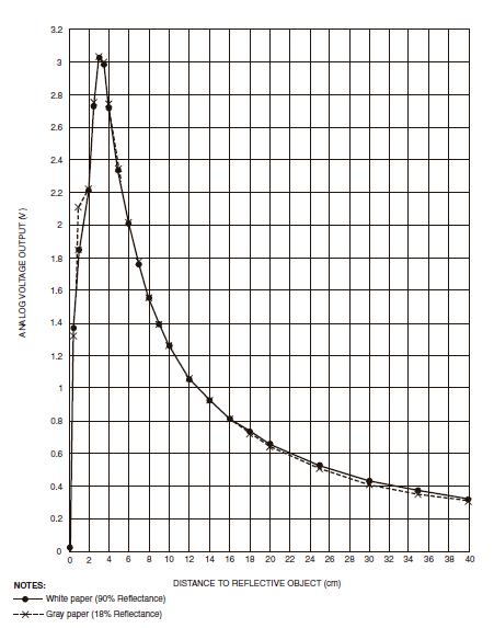
Figure 1. Distance vs. Voltage IR
Sensor
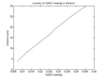
Figure 2. Linearized Sensor Output
The ISR also controls the DDS, which generates a
sinusoid based on values input from the user. The DDS has a 32 bit adder
called accumulator, in which the top 8 bits are used as an index to poll values
from the sine sinetable in PROGMEM. During every iteration of the ISR, an
increment is added to the accumulator. The value of the increment is
determined during runtask(), and is the selected burst frequency multiplied by
272187. Increment = (freq_out*2^32)/15780. The index (top eight bits)
will then generate a sinusoid via the sine table as the increment changes the
value of the accumulator.
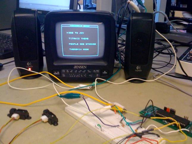
The Theremin Hero game consists of 4 main
components: the photoelectric sensors, the audio output, the video output/game
generation, and the song encoding. Each
component is discussed in more detail immediately below, and illustrated in
figure 3 below.
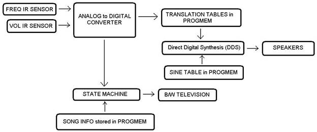
Figure 3. High Level Structure
Sensors:
One photoelectric sensor is a dedicated ‘pitch’
controller, while the other is a dedicated ‘volume’ controller, each operated
by adjusting the distance between the sensor and the hand of the user. The sensors have a range of 4-30cm and
typically produce an analog voltage of 0.0V-3V that is proportional to this
range. This analog signal is passed
along to the MCU, where the ADC converts these analog signals into discrete
values. See the software tradeoffs
section for a discussion of loss of precision in the ADC conversion stage. The analog signal from the sensors is
non-linear in nature; the values closest to the sensors are most sensitive to
change. It was desired that movement of
the hands along the sensors' paths would produce a linear response so that
frequency intervals and volume levels both had uniform step sizes. The digital
values output from the ADC are processed with a linearization function in order
to accomplish uniform step sizes. See
the software tradeoffs section for a discussion of the loss of precision
associated with the linearization function.
Audio:
The audio component uses the discrete pitch and
volume values converted from the photoelectric sensors to output a monophonic
tone of variable frequency and amplitude.
This tone is generated using direct digital synthesis (DDS), and a
simple RC filter is used to low pass filter the generated signal. The low pass filter circuit is discussed in
more detail in the hardware details section below. The Theremin has the ability to output a
continuous range of frequencies between C (262HZ) and D# (622Hz), which are
scaled to be linearly proportional to the user's range between 4 and 30cm from
the sensors respectively. The DDS
function can only create a sinusoidal function with amplitude of 1 or less, so
the max volume is set to an amplitude of 1 and subsequent decreasing volumes
scale down to 0, scaled in a linearly proportional manner to the user's range
between 30 and 4 cm, respectively. A
detailed discussion of this DDS implementation can be found in the software
details section.
Video Output:
The third component of Theremin Hero is the video
output and game generation. The video
output circuit is implemented exactly as in the lab 3 instructions, using a DAC
to drive the video and sync inputs to the CRT.
This circuit is discussed in more detail in the hardware details section
below. The video game itself is
generated in multiple incremental states to avoid timing issues associated with
printing to the CRT. The time taken to
paint images on the screen is very time intensive and processing time and space
is already taken for the ADC and DDS components. Accordingly, extra effort was taken to find
creative ways to print images only once and avoid having to erase those images
as the game progressed. These solutions
are discussed in the software details section.
Ultimately, there are 8 states in the video game, providing fluid
operation for a game that consists of a main menu, training mode, and three
programmed songs. The user selects
options on the main menu by moving the ‘pitch’ hand to choose amongst options,
and lowering the ‘volume’ hand to select the highlighted option. In order to go back to the previous menu, the
user must lower both hands so that the sensor values are minimized for a length
of two seconds. In game mode, users move
their hands towards and away from the pitch and volume sensors and see
immediate adjustment of the dots representing their range on the sliding bars. This feedback is necessary so that the player
can match the current pitch and volume governed by their own movement to the
preprogrammed songs that are scrolling from across the screen. See the images in the program design section
for various menus and game modes.
The final component of the Theremin Hero game is the
preprogrammed song protocol. The
selected songs are ‘Ode to Joy’, the Titanic Theme, and ‘Greensleeves’, in
increasing order of difficulty. Sheet
music was taken for each song and transcribed into binary; two bytes for each
note, one byte representing the pitch of the note and one byte representing the
volume. There are sixteen discrete
notes and sixteen discrete volume levels that can be printed to the screen,
with encoding for note duration, pauses, crescendo and decrescendo, which the
user must match with their Theremin playing abilities. These bytes are stored in PROGMEM and read
incrementally during the game mode. A
discussion of the encoded song protocol and the process for reading in this
information during game play is discussed in the software detail section below.
There were numerous tradeoffs during the development
of Theremin Hero. In general, preferred
alternatives for every option were selected based on impact on budget, impact
on limited time budget, and the effect on quality of experience that the end
user would experience.
The first choice was in the strength of the sensors
versus the cost associated with improving the quality of infrared sensor. For Theremin Hero, a 10-80cm sensor would
allow for a generous range of DDS generated frequencies, but it was quickly
realized that working with a 5” black and white CRT was a limiting factor to
the broad range of the sensors.
Ultimately, the 4-30cm sensors were a sensible compromise between
sensing range to be delivered to the ADC, and affordability. The two sensors represented approximately 33%
of the total allocated budget, and were a significant investment. Fortunately, this was the most costly
component of the hardware required to implement Theremin Hero.
The second tradeoff was choosing between linearizing
the sensor or leaving the sensor output as a nonlinear function with respect to
distance. For the user, a more intuitive
experience would call for a linear relationship between notes (although note
that as higher notes are reached the distance between notes increases). Linearizing the sensor output, however, meant
artificially weighting the less sensitive component that existed at the very far
edge of the sensor’s range. Ultimately,
it was determined that making the user’s experience of playing notes as similar
to conventional instruments as possible was important. Linearizing the sensor output is discussed in
the program design section.
Another decision regarding the sensor output
centered on selecting the reference voltage for the analog to digital converter
(ADC). Based on the values of REFS0 and
REFS1, the AREF comparison voltage can be 5V, 2.5V, or 1.1V. Given that the sensor voltage ranges from 0
to 3V, by using AREF at 5V the ADC output is limited to values ranging from 0
to 160, as opposed to values from 0 to 256 if the sensors ranged from 0 to
5V. Although this reduced the working
range of the ADC, the alternative was to set AREF to 2.5V. This setting would exclude the values from
about 5cm and closer to the sensor from being processed by the ADC. The slight loss of precision associated with
setting AREF to 5V was deemed appropriate given the overall resolution of the
system. See the calculated voltage and
pitch tables in the program design section for an elaboration on how the 160
value range was utilized to produce the audio and visual output of Theremin
Hero.
The final major tradeoff was the economic/time
tradeoff decision that lay between utilizing the pre-existing STK500 as the MCU
control board at significant cost versus soldering a custom PC board and
risking crucial troubleshoot time associated with bringing the board into
operation. Due to the initial project
proposal that called for two MCUs, the project costs closely approached the $75
limit. In order to alleviate the
proximity to this ceiling and provide more room for unseen contingencies, a
custom PC board was constructed. Two major
issues befell the construction of the PC board, costing a significant amount of
time in troubleshooting at the benefit of saving numerous dollars in STK500 and
jumper cable rental. See the hardware
design section for an elaboration of the PC board issues.
One of the relevant standards related to this
project is the NTSC standard for video signals in the US. Theremin Hero implemented the same scheme for
printing to a CRT as what was used in Lab 3 of ECE4760. This scheme is different from the NTSC
standard in that the NTSC standard uses interlacing and in this project
interlacing was not used. However, in line with NTSC standards the video
display is painted at the rate of 60 Hz.
Existing
Patents, Copyrights, and Trademarks:
At this time there is no commercial version of
Theremin Hero, and accordingly there are no intellectual property issues to
consider. There are open source
development projects for both traditional and digital Theremins, encouraging
hobbyists to contribute new ideas to the world of hands-free instrumentation.
Overview:
The software design for Theremin Hero utilizes a
single MCU to execute the following high level tasks: process analog signals from
two sources through a single ADC, generate monophonic audio over a XX Hz range,
generate a visual display on a CRT, and drive a game play state machine
featuring an options menu and multiple stages.
Different components of the software include standard libraries,
pre-supplied code, calculation tables, an Interrupt Service Routine, the main()
routine, and main() subroutines. Each of these components is described in
detail below.
Standard Libraries:
The following header files were included in the
software for the following reasons:
#include <avr/io.h> - standard I/O definitions
for the AVR board.
#include <avr/interrupt.h> - compiler specific
interrupt code.
#include <avr/pgmspace.h> - support for
accessing data in flash memory.
#include <stdio.h> - standard input/output
operations used for displaying relevant info.
#include <stdlib.h> - general purpose standard
library
#include <util/sleep.h> – support for the
sleep function – wait reliably for specified interval
#include <avr/sleep.h> – support for the sleep
function – wait reliably for specified interval
#include <inttypes.h> -printf and scanf
support
#include <util/delay.h>- support for delay
loops
#include <math.h> -support for sinusoidal
calculations
#include <string.h> - support for string handling
Pre-supplied Code:
Components of the code used for both video and audio
generation were adapted directly from labs 3 and 2, respectively. The following sections detail code that was
not changed from supplied programs.
Video-
An important aspect of printing information to the
television consists of predefining characters, numbers, and small images. As part of the initialization for this
program, all letters and numbers are predefined as two dimensional maps of high
and low bits. The routine byteblast() is
included to write 18 bytes to the screen, using the macro asm(). All are unchanged from the supplied
video_codeGCC644.c code.
In addition to predefined chars and numbers,
Theremin Hero uses the following routines from the video_codeGCC644.c code:
video_pt(), video_line(), video_putchar(), video_puts(), video_smallchar(),
video_putsmalls(), video_set(). The
purpose of these ancillary routines is to print various points, lines,
characters, and strings of characters to the CRT. These routines have not been altered in any
way, but their importance to time-relevant printing makes their recognition
worthwhile.
The timer 1 ISR from lab 3 has been modified, but
was used as a design guide. See the ISR section below for further detail.
Static messages that are printed once, and left on
the screen for a specified duration, are predefined and stored in progmem. Examples of these predefined messages include
the title “Theremin Hero” and “Titanic Theme”, which remain painted on the
screen for entire duration of some states in the game. To access these strings from memory, the
function call pgm_read_byte, which was unchanged from the source code, was used
to read each byte of the string.
Audio-
Direct Digital Synthesis in Theremin Hero utilizes
an identical algorithm to the process in lab 2, but is implemented in a
slightly different manner. As in lab 2,
a sine table was calculated in advance for use in generating a sinusoid (see
calculation tables section immediately below).
The accumulator and increment are the same from lab 2, and the manner by
which sine values are taken from the table and used as part of the new value
for OCR0A during the Interrupt Service Routine is the same as in lab 2. The difference in this PWM code is that the
value increment, which adjusts the frequency for the generated sinusoid, varies
with the the values for pitch that are brought in from the ADC. Similarly, the value vol_lvl that controls
the amplitude of the generated sinusoid varies with the values for volume that
arrive from the ADC. Lastly, there is a
toggle bit called 'sound' that allows for the generated tone to be turned off
during select times, such as in the game menu.
Altogether, although the high level practices for
programming video and audio output were taken from labs 3 and 2, the actual
implementation of these features for Theremin Hero required significant
adjustment.
Calculation Tables:
In addition to the large tables of predefined
characters that are used for video output, multiple tables of pre-calculated
values were necessary to speed up time sensitive routines.
A sine table
calculated in Matlab and copied over was necessary for sinusoid generation in
the ISR. The values in the table are
simply 256 samples of a sine wave generated in matlab that has amplitude
127. The amplitude 127 represents the
maximum amplitude that can be reached (and accordingly this is the max value in
the pre-calculated linearized volume table, described below). These values are used to recalculate
'increment' during the generation of a sinusoid.
In addition to the sine table, two arrays of length
161 were calculated to be used in linearizing the outputs of the photoelectric
sensors processed by the ADC. The arrays
are indexed from 0 to 160. This length
was determined based on the fact that the sensor output ranges from 0 to 3V,
while the AREF of the ADC is 5V. The
output of the ADC is 10 bits long, but only the top 8 bits in register ADCH are
retained. Accordingly, the maximum value
of the ADC is Vin*1024/(Vref*2^2)=161.
The output of the ADC, which remains nonlinear in behavior, is fitted
with a linearization function (as shown in the background math section) and
these values are set in the precalculated pitch and volume tables. During the game, the output of the ADC, which
is between 0 and 160, is used as the index for accessing the scaled linear
value that will be used in generating sinusoids and printing level indicators
on the screen.
Interrupt Service Routine:
Both the audio tones and video display are managed
within the timer 1 Interrupt Service Routine.
ISR(TIMER1_COMPA_vect) catches the overflow of timer1. The ISR is entered on the trigger of timer1,
which occurs every 1018 ticks of the clock (at full speed). By triggering the
ISR at this time, the entire video screen is updated 60 times per second. The
main() routine ensures that sleep() has been enabled before the ISR is entered,
thus ensuring that the sync pulses generated by the ISR are coordinated in
time. The process for managing the sync
pulses via the variable linecount remain unchanged from lab 3.
The Analog to Digital Converter is controlled in the
ISR. Every 1/60 seconds the variable
linecount, which manages the sync pulses, reaches a value of 1 before being
reset. When linecount=1 the ADC will
perform a conversion for either the pitch or volume sensor. The variable ADChoice is toggled to ensure
that each sensor is sampled in an alternating fashion, 30 times per second
each. The ADC converts the sensor
voltage of between 0-3V to a value between 0-160, governed by the equation in
the background math and tradeoff sections.
The ADC value is linearized, as discussed in the calculation table
above, before being used to update the DDS generated sinusoid within the main
section of the ISR.
The DDS takes place in the main body of the ISR,
meaning that OCR0A is updated 15780 times per second
(60Hz*263lines/frame). The DDS, as
discussed in the pre-supplied code section, uses the linearized values taken
from the ADC to calculate an increment value for frequency and a vol_lvl for
amplitude. The accumulator is
incremented by the adjustable 'increment' value, allowing the speakers to play
frequencies varying between 262 and 622 Hz.
The value assigned to OCR0A is multiplied by 'vol_lvl', which is scaled
by the calculation table to allow the speakers to play sinusoids with an
amplitude of between 0 and 1.
Main():
Initialization-
The beginning of the main routine includes standard
initialization of registers that are unchanged from the video display settings
of lab 3. The timer 1 control bits are
set so that frames have a duration of 1/60th of a second. The PWM variables are also initialized just
as in lab 2, with port B3 set as the output port. As a default, increment is initialized as
272178*440, representing a starting frequency of 440Hz. As 272178= 2^32/15780, where 15780 is the
number of times the ISR is triggered per second, 272178 represents the scaling
factor used to generate the 440Hz tone in the ISR. The vol_lvl variable is by default set to max
at 127, which is scaled to 1 in the ISR - as discussed above. Also included in the initialization portion
of main() are initialized values for the ADC, static print content for the
video display, and cleared variables for the game state machine. Local variables required for the state
machine include: state-keeps track of the current state, temp-used as a general
dummy variable throughout each state, timer-used to delay the transition between
states for both aesthetic and display management purposes, toggler-allows for
alternation between printing pitch, volume, and scoring status for timing
purposes , note_timer-holds the duration of a given note based on the note's
encoding in progmem, and draw_timer-controls the frequency with which scrolling
notes are displayed. The coordination of
these variables is discussed in the while(1) loop below.
while(1) loop-
Within the repeating loop, the first command is
'sleep_cpu()'. This call ensures that
when the program enters the ISR the timing of the sync pulses for the video
output will be accurate. 60 times per
second, or when linecount=231, main() enters an extensive switch statement that
serves as the main state machine. There
are 8 states in this switch statement: MENU, SELECT, DRAWMODULE, SONG1, SONG2,
SONG3, THERMODE, and CLRSCREEN. A
summary of the state machine is illustrated in figure 11 below at the end of
this section. The initialized variable
'state' is set to MENU, in which the menu is printed using
video_putchar(). The four options
available are 'Ode to Joy', 'Titanic Theme', 'Greensleeves’, and 'Theremin
Mode'. See figure 4 below for an image
of the menu state.
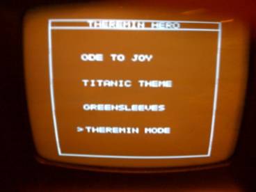
Figure 4. Menu State
The state is
then set to SELECT, which allows the user to select one of the four game modes
by adjusting the pitch hand to select an option, and lowering the volume hand
to select that option. 'temp' is used to
determine which option the user is selecting based on the height of the pitch
hand. 'temp' is set in proportion to
'increment', meaning that if the user holds the hand above a certain threshold
they are selecting some option on the screen, and the cursor next to the
selected option is adjusted accordingly.
Given a certain selection with the pitch hand, 'temp' is then assigned
to the vol_lvl which is proportional to the volume hand's height. If the hand has been lowered below 20 on a
scale of 0-127 for the volume sensor, the user has selected that option. Upon selection, the three other menu options
are erased using video_putchar() of a blank space and the variable timer is set
to 60. Setting timer to 60, while the
while(1) loop breaks out of sleep 60 times per second, means that the selected
option is displayed for one second before the game begins painting the selected
new state. The state then progresses to
DRAWMODULE. The drawmodule state consists of painting the components of the
video display that are common to all four options: the pitch and volume
indicators, the boxes framing those indicators, and the words 'FREQ' and 'VOL'
written vertically next to their respective boxes. Based on the selected option from SELECT, the
state progresses to either SONG1, SONG2, SONG3, or THERMODE. Not that although the name of these states
are printed to the screen during a respective state, this had to be deferred to
the subsequent state due to timing issues.
THERMODE is simply a practice mode in which the pitch and volume
indicators are functional, sound is enabled, and the user may practice using
the Theremin. While growing accustomed
to the digital Theremin, Theremin prints the note that the user is currently
playing, giving the user a better idea of the range of the game. Thermode is shown in figure 5 below.
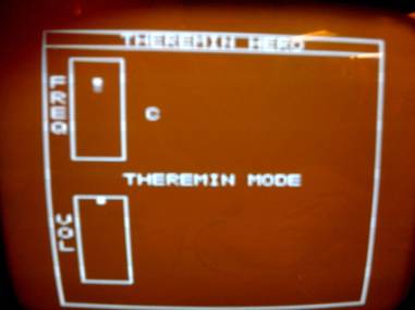
Figure 5. Theremin Mode, playing High
C
In order to leave
Theremin Mode and return to the main menu, the user must lower both hands to
the lowest possible levels for one second.
States SONG1, SONG2, and SONG3 vary only in the type of song being
displayed, so a generic SONG state will be described in detail. In each SONG state the song title is printed
only once in the center of the screen, the sound is enabled and local variables
are reset to 0. Of particular note is a
new array called transitions[i], which holds information for four song notes to
be displayed on the screen at one time.
Once this initial state occurs, there is a second clause that governs
the song notes to be displayed for a given song. Each of the three songs has the song stored
in two arrays that separately hold the song's pitch and volume
information. Each note has one 8 bit
byte encoding pitch and one byte encoding volume; figure 6 below illustrates
the scheme.
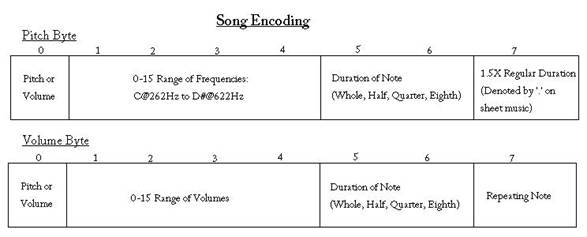
Figure 6. Song Encoding
The arrays
are accessed by index number, with the first note being i=0. For a given note, the two 8 bit bytes are
read in from progmem and held in 'temp'.
The frequency bits are shifted by 8 bits to accommodate both bytes. A switch statement reads the pitch byte for
information about the song note, determining the duration of the note (whether
whole, half, quarter, or eighth) and sets the duration of note_timer
accordingly. The transitions[i] array is then shifted forward so in to
transitions[0]. The index of the song
tables is then incremented. Following
this processing, the SONG state then updates either the user's pitch position,
the user's volume using the subroutines printfreq() and printvol()
respectively, depending on the variable toggle.
The variable ‘toggle’ also controls when the current score is printed to
the screen; printfreq(), printvol() and printing the score alternate in such a
way that each are printed to the screen 20 times per second, as shown in figure
7 below. This functionality of this
state machine is explained in detail in the scoring section below.
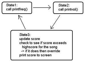
Figure 7. Scoring/Vol/Pitch Print
State Machine
Each of the
three game play modes are shown in figures 8, 9, and 10 below.
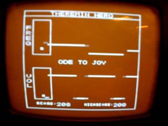
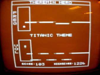
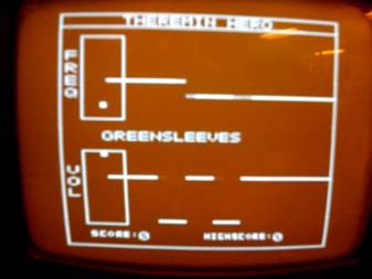
Figure 8. Level 1 - Ode to Joy
Figure 9. Level 2 - Titanic Theme
Figure 10. Level 3 - Greensleeves
The
variable draw_timer is also incremented
only when updating the user's indicators, causing the subroutine drawsong() to
be called only 15 times per second.
Note_timer, the variable that stores the duration of the given note in
transitions[0], is then decremented and a new note is not read in until
note_timer decrements to 0. This process
repeats until the end of the song table index is reached. The sound is then disabled, and the pitch and
volume indicators are erased. Lastly,
SONG increments timer up to 60, at which point (one second later) timer is
cleared and the state is progressed to CLRSCREEN. The purpose of CLRSCREEN is simply to clear
the screen - albeit in incremental stages that prevent timing issues that crash
the game. The information printed by
DRAWMODULE is first erased, and one second later the song title is erased. The state is reset to MENU, and the game
starts anew. In summary, the main() repeating loop controls the state machine
that drives game play.
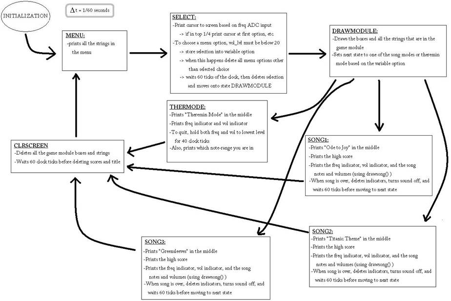
Figure 11. State Machine Overview
Scoring:
The scoring system is implemented in the printfreq()
and printvol() functions and in main within the state machine. While the song
is being printed to the screen during states SONG1, SONG2, or SONG3, the
functions printfreq and printvol will check to see if there is a line next to
the square indicator drawn on the screen. This is done by using the provided
function videoset(). This function returns a character value stating whether or
not the selected pixel is being used (painted on). If there is a line,
indicated by a white pixel, next to the pitch or volume indicator, then the
correct frequency or volume is being played, respectively. In that case, one
point will be added to the score. However, if both volume and frequency are
being played correctly, a bonus will be added, and 4 points will be added to
score.
A mini state machine controls this process within
the states SONG1, SONG2, and SONG2 show below in figure 7 above. First,
printfreq() is called. If the user input leads to the frequency indicator to be
located at the correct location, then one will be added to point. On the next
time through, printvol is called, and depending on whether or not the volume
indicator is in the correct location, one could be added to point. On the next
iteration of the main state machine, the points are added to score. First, it
checks to see if ‘points’ is 2, if this is the case, then both volume and
frequency are correct, so four is added to the score. Also at this time, the
score is printed to the screen. If the score of the user exceeds the high score
for the song, then the high score for the song is updated and also printed to
the screen. Thus, if a high score is achieved, the high score updates
automatically.
Subroutines:
There are three subroutines utilized during the SONG
states of main() to print relevant game play information to the screen: printfreq(), printvol(), and drawsong(). printfreq() and printvol() are related to
updating the indicator on the screen for pitch and volume, respectively. These routines are simply extensive if-else
clauses that determine which of sixteen discrete levels the pitch or volume
(which is a near continuous value) lies within.
This range then sets the dummy variable i, which is used to first erase the
existing indicator square and then repaint the indicator in its new level.
drawsong() is the function used to draw the notes
and volume for the songs stored in progmem.
It is called in the SONG1, SONG2, and SONG3 states of the main state
machine. The function knows where to print notes based on the array
transitions[i]. In the state machine, when a new note is to be printed, it is
added to the beginning of the array (index 0) by shifting all array elements up
one index. In transitions[i] 3 pieces of information are stored: the note’s
frequency (note), the note’s volume level, and the note’s boundary value (where
on the screen the front of the line representing the note’s beginning exists).
In the function drawsong(), a for-loop is used to go through all the values in
the array. frequency and then volume are printed. For frequency, the past
note’s frequency must be “deleted” so that the current note can be printed in
that horizontal slot on the screen. Then, the frequency for the current note is
printed as a line. More than just the exiting note is deleted, such that there
is an extra gap to distinguish between notes. Each call of drawsong() advances
the note by 5 pixels on the screen. To make sure that no notes go past the
frequency indicator on the screen, the function only draws notes that have
their beginning point greater than the horizontal position of 21 (the right
most boundary of the indicator). Volume is treated differently since at the end
of each note, the volume must be dropped down to the lowest level so that it
can be distinguished as a separate note from the previous note. Instead of just
deleting old lines and replacing it with the new value, more of the old line is
deleted, and replaced with a low level
volume line.
‘note_timer’ is used to ensure that the timing for
each note is executed properly. This
timer is set according to the length of the note from encoding scheme in
PROGMEM. In each execution of the state machine, note_timer is decremented
once. New notes are only added to the transitions[i] array once the note_timer
has hit zero. Thus, the timing for the new notes works as it is supposed to.
The value note_timer is set to when a new note is added is determined by a
switch statement: Whole notes being twice as long as a half note, which are
twice as long as a quarter note, etc.
To make sure that the notes move across the screen
at a reasonable rate, another timer (draw_timer) is used. This timer controls
how often the drawsong() function is called. It is incremented every execution
of the state machine. In testing, it was determined that drawing the new lines
for the song every 5 ticks of the state machine clock (12 times per second)
produced an acceptable rate for the lines on the screen.
The hardware setup design for Theremin Hero was
fairly simplistic, although complications arose during the implementation of
the design. There were four main
components to the hardware: the sensors, the video output, the audio output,
and the custom protoboard for the MCU.
The sensors are Sharp GP2D120 IR rangers, with a simple signal, Vcc, gnd
contact scheme. The contact
configuration for the sensors is shown in figure 12 below. The pitch sensor output is connected directly
to port A0 on the protoboard, while the volume sensor is connected to port
A1. The sensors require 5V supply power,
supplied by the protoboard. The sensors'
respective grounds are also made common to a common ground with all other
hardware components. An interesting
design problem arose when it was realized that the sensors draw more current
than is permitted by the voltage regulator of the protoboard. This issue is discussed in more detail in the
hardware description of the protoboard below.
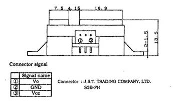
Figure 12. GP2D120 PINOUT
The video output circuit is identical to the circuit
used in the lab 3 design. This circuit
is reused because the desired functionality of the CRT is identical to its
usage in lab 3. The schematic is included in figure 13 below. The circuit consists of one 330Ω
resistor, one 1kΩ resistor, and one 75Ω resistor. The port pin D5, which drives the video
output, is connected to the 330Ω resistor, while the sync output on port
D6 is connected to the 1kΩ resistor.
These two resistors are both made common with the 75Ω resistor,
which goes to ground. The video output
is taken from the common point between the three resistors.
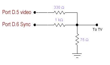
Figure 13. ECE4760 Video Output
The audio output circuit is a simple low pass filter
used to clean up the synthesized tone before being amplified by the
speakers. The low pass filter is
illustrated in figure 14 below, and is reproduced exactly as in lab 2. The lpf consists of one 10kΩ resistor
and one 10nF capacitor. The prefiltered signal from port B3 is fed into the
resistor, which is connected to the capacitor.
The capacitor goes to ground, and the common point of the resistor and
capacitor is the audio output to the speakers.

Figure 14. Low Pass Filter Audio Output
The most complex and time intensive component of the
hardware setup was the protoboard.
Soldering of components onto the board was completed as per Professor
Land's instructions, and the board appeared to function correctly for test
programs. Figures 15 and 16 below show the schematic of the board and an image
of the completed board in the circuit.
The protoboard, however, did not function correctly in the Theremin Hero
circuit. The first issue with the
protoboard was that the supplied voltage regulator, the LM340LAZ-5.0, was rated
for the desired 5V but limited the supply current to 100mA. After reviewing the sensor data sheets, it
was realized that the sensors draw anywhere from 33 to 50mA each. With the Mega644 drawing approximately 35mA,
it was determined that a larger voltage regulator was necessary. The LM340T5, with 5V regulation and 1A limit
current, was soldered on to the circuit.
The video and audio quality improved noticeably, but the sensors
continued to be unresponsive. Further
troubleshooting revealed that the ADC pin AREF was set to 0 volts on the
protoboard. When testing with the STK500
board, the ADC settings for REFS1 and REFS0 were such that an external Vcc
reference was being used. Without the
Vcc reference, the ADC on the custom protoboard was non-functional. By changing REFS1 and REFS0 to a setting that
used Vcc internally, the ADC immediately became functional.
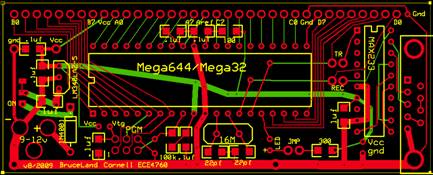
Figure 15. Supplied PC board schematic
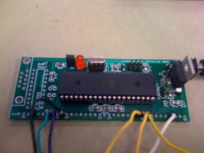
Figure 16. Soldered PC Board
Circuitry and Code reuse is discussed in the
software and hardware design sections above.
The Theremin Hero game is almost identical to the
tentative design in the project proposal, but for a few minute changes. During the design phase it was realized that the
two MCUs called for in the design would not be necessary if the software was
designed to carefully consider timing issues.
Using only a single MCU, there were immediate problems with the timing
associated with reading the sensors, creating an audio signal, and drawing to
the screen concurrently. The first failed consideration was concerning the
frequency of reading in two analog signals, the pitch sensor and volume sensor,
in to a single ADC at every complete cycle of the video ISR (60Hz). This caused the screen drawing to freeze, so
the design was changed in the ISR so that the ADC alternates between sensors,
and samples 20 times per second.
Another problem arose in the linearity of the
sensors. During Theremin Hero design it
was not realized that the sensors are nonlinear with respect to the users’
hands from the sensor. Although the
sensors would still function correctly, intuitively a 1cm movement at either
the near end or far end of the sensors range should translate to an equal
change in pitch or volume. Wanting the game to be as intuitive as possible, a
linearization function was fitted to the signals from the sensors. This function, described in the software
design section, caused a timing issue due to the time to compute the linearized
values. Precalculated tables were
generated in Matlab that, like the sine tables for PWM, were used to quickly
linearize the ADC values. The tables
resolved the timing issues.
The final timing issue arose during the
implementation of the game on the video display. The initial design called for a minimal
number of states, such as menu, game one, game two, etc., that would progress
intuitively. Due to the small amount of
time and finite memory allotted for printing to the screen, numerous
intermediate states were introduced that would either draw or erase in
incremental steps in order to avoid timing overflow. This had the effect of complicating the
game's state machine, but allowed for more relevant information to be printed
to the screen.
Lastly, the most time consuming hurdles arose during
the construction and implementation of the custom protoboard for the
mega644. The voltage regulator or (How I
learned to stop worrying and love the mega644) was undersized for our design
and had to be replaced with a larger model.
The larger model LM340T5 was rated for 1A at 5V output, as opposed to
the 100mA rating for the LM340-5.0.
Additionally, the AREF control bits were configured in a manner that
allowed for correct operation on the STK500 but not on the protoboard. These difficulties are discussed in the
hardware design section above.
Managing timing constraints was the most important issue
faced in the development of Theremin Hero.
Creating seamless game play with gapless audio and clean visuals came at
the cost of extra complexity in the game's state machine. Occasionally, transitioning between states,
and having to clean the screen and move to a new screen, required intermediate
steps that could perform the transition in stages. These incremental states between enduring
states are certainly noticeable, making the transition time non-negligible, but
do not interfere with overall game play.
Otherwise, the game suffers from minimal audio noise, no flicker or
artifacts on the CRT, and no lag between the user's movements above the sensors
and the corresponding movement on the screen.
To the user, the game reacts instantaneously to any movement by the
user, and transitioning between game modes and the main menu is hands free,
flicker free, and intuitive.
The entire purpose of Theremin Hero is to match
notes displayed on the scrolling screen to played notes on the Theremin; accuracy
is the main purpose of this game. From a
music generation standpoint, the song notes that are programmed into the game
are precisely the sixteen notes between C at 262Hz and D# at 622Hz. The user must align their pitch and volume
sliders as accurately as possible to the song notes. The pitch and volume indicators move up and
down sixteen discrete levels, so it is possible that the user can show the
pitch indicator as matching a given song note without the played note being
exactly the same. For example, the user
may have 445Hz playing from the Theremin and thinking this is A at 440 Hz
because the indicator sits at a level for a small range of frequencies. This problem cannot be remedied unless the
Theremin itself plays only 16 discrete notes instead of a continuous
spectrum. Although this option was
considered during the design phase, it was decided that staying true to the
original Theremin by keeping a continuous spectrum tone generator would be more
appropriate.
Another measure of accuracy was the video signal
timing. The accuracy of the video
display coordination with the rest of the game system can be seen by the quick
response time for changing the user's hand position and seeing the
corresponding change of the indicators on the screen. As each sensor is sampled 15 times per two
seconds, the user would view a very accurate and expeditious timing system.
From a safety perspective, Theremin Hero is arguably
safer than any music-themed video game currently on the market. Horror stories of drum sticks smashing
through LCD television screens, guitars being wind milled into friends, and
High-F notes shattering glass are not concerns with the hands-free
Theremin. With the exception of rotation
at the elbow and wrists, the user may remain completely still while playing the
game, minimizing the risk of strain or stress.
Safety was emphasized to an even greater degree by opting for the 4-30
cm sensors as opposed to the 10-80cm sensors.
Imagine the stress and strain of air windmills and jumping up to hit the
High F! The 4-30cm sensors keep the arms
within a very manageable and safe 26cm vertical zone.
Interference:
Theremin Hero is a non-transmitting, non-interfering
system that did not experience any significant noise from other group projects,
and does not interfere with any other groups.
The only potential source of interference would be sources of infrared
light that may impede the rangers' measurements. There did not appear to be any such source in
the lab.
Usability:
This game is highly useable. The controls are simple and intuitive, making
the game appropriate for people of all ages.
The game is actually very challenging for levels in which both pitch and
volume adjust simultaneously; gamers who love a challenge will find this game
very useable as they try to beat the saved high score.
At this time, there is no significant adjustment in
place for users with special needs.
Theremin Hero could be played by anyone, but special consideration will be
necessary for the visually impaired and for those users who do not have two
functioning arms. The photoelectric
sensors will sense any object in their line of sight, so it would be possible
to play by extending any object over the sensor (for example, a
prosthetic). For the visually impaired,
perhaps it would be appropriate to play the correct tone first before beginning
the game, so the user has an idea of the desired notes. Theremin Hero has not yet been implemented
for the visually impaired.
Comparison to Expectations:
The final version of Theremin Hero features all of
the attributes included in the initial project proposal, with a few additional
features added that were not in the original scope. Given that there was only a month to
integrate all of the Theremin Hero modules, we set realistic milestones for
ourselves in planning the development of the game. Goals for the project
included having two fully functioning photoelectric sensors that would control
the pitch and volume of a generated tone and of two indicators on the CRT. The game would feature a menu that the user
could navigate using pushbuttons, and feature challenging levels of game play
that would be simply to understand but difficult to master. A high score for each level would create a
sense of purpose for the user. The game
includes all of these attributes, but modified the goal of using pushbuttons by
finding novel ways to navigate forward and backward through menus with the
sensors alone. Additionally, the initial
proposal called for the use of two communicating MCU units. After careful consideration, all of the game
functions were implemented on a single MCU.
This required a substantial effort to make the program as lean as
possible, and create numerous intermediate states to avoid timing and
computation issues. In summary, the
Theremin Hero game not only met all key attributes described in the project
proposal, but improved upon many components of the initial design.
Compliance with Standards:
Theremin Hero is a closed system that does not
transmit or communicate with any peripheral devices or systems. The only near-applicable system for the game
was the NTSC standard for producing video output, but because the scheme from
lab 3 was used for displaying the game (a scheme that does not use interlacing)
the NTSC standard was not followed.
However, to avoid flickering on the screen the refresh rate of the CRT
was 60Hz, as per the NTSC standard.
Intellectual Property Considerations:
At this time there is no commercial version of
Theremin Hero, and accordingly there are no intellectual property issues to
consider. Further, as there are no
commercial versions of this game there are no patent or trademark concerns. There are open source development projects
for both traditional and digital Theremins, encouraging hobbyists to contribute
new ideas to the world of hands-free instrumentation.
Given that the Theremin community encourages open
source development and collaboration, it would be a slight to the memory of
Leon Theremin to patent and commercialize this unit. This would, however, be a fun and relatively
simple project for hobbyists to implement if our program was published and made
available online. Then again, if there
are dollars to be made perhaps it is time to give Nintendo a call.
Ethical Considerations:
Given the ubiquity and influence of technology in
today's society, the IEEE code of ethics is a crucial ethos for an organization
that has such a direct connection to the quality of life for much of the
world's population. Accordingly, it is
of high importance that our decisions regarding the design and implementation
of Theremin Hero aligned with this code.
Although Theremin Hero obviously does not affect the livelihood or
safety of others in a significant way, we recognize the importance of learning
these tenets now as we prepare to transition into the professional engineering
community.
As per the first guideline, we kept the safety of
the 'public', in this case the game user, in mind while designing the
unit. The sensors are kept isolated from
the unit's main circuitry by long leads.
Further, by their very nature the sensors are inherently safe as the
user does not ever need to place their hands on the game. Voltages are maintained at safe levels (on
the order of 5-12VDC), and there are zero moving parts that may harm the
user. Lastly, the game does not transmit
interference, and so cannot interfere with communication devices.
As per the third guideline, this report was written
in a truthful and transparent manner.
The source program is included in the appendices, as has been unedited
from the working version programmed on the MCU.
Shortcomings of the system are discussed throughout the report, and
claims are neither overstated nor deceptive.
As per the fifth guideline, this project allowed us
to broaden our understanding of many facets of microcontroller design and
implementation. Troubleshooting and
making incremental changes were our preferred methods of figuring out how and
why different methods worked in different manners, thus broadening our
understanding of technology.
As per the seventh guideline, we have made a strong
attempt to keep the TA's and Professor Bruce aware of our progress and be as
transparent as possible with our work over the past few weeks, welcoming
criticism and help as we achieved key milestones. Further, credit has been given to the source
code that was used as a framework for parts of Theremin Hero in the main body
of the report.
Legal Considerations:
It must be illegal to have this much fun playing
Theremin Hero! As discussed in the
results section, this device does not transmit or communicate with external systems,
and so does not infringe on any guidelines or restrictions. Further, there are no known
patents/trademarks that prevent the legal development of this design.
Code
|
Theremin Hero Budget |
|||||
|
Item |
Part # |
Manuf. # |
Vendor |
Quantity |
Cost |
|
Whiteboard |
- |
- |
ECE4760 Lab |
1 |
$6 |
|
Power Supply |
- |
- |
ECE4760 Lab |
1 |
$5 |
|
Custom PC Board |
- |
- |
ECE4760 Lab |
1 |
$4 |
|
Mega644 |
- |
- |
ECE4760 Lab |
1 |
$8 |
|
Audio Speakers |
- |
- |
ECE4760 Lab |
1 |
- |
|
B/W TV |
- |
- |
ECE4760 Lab |
1 |
$5 |
|
Alligator Clips |
- |
- |
ECE4760 Lab |
4 |
$1 |
|
Port Pin Headers |
- |
- |
ECE4760 Lab |
8 |
$0.05 |
|
IR Sensor GP2D12* |
R48-IR12 |
GP2D12 |
2 |
$12.50 |
|
|
Total Cost |
|
|
|
|
$57.40 |
|
Total Budgeted |
|
|
|
|
$75.00 |
|
Division of Labor |
||
|
Task |
Sam |
Dave |
|
Circuit Construction |
X |
|
|
Integration of Video
and Audio output code |
|
X |
|
ADC linearization
functions |
X |
X |
|
Encodings songs into
progmem |
X |
|
|
State machine design |
X |
X |
|
Implementation of
State Machine |
|
X |
|
Soldering of custom PC
board |
X |
|
|
Troubleshooting
insufficient components |
|
|
|
of custom PC board |
|
X |
|
Design and
implementation of scoring algorithm and display |
X |
X |
|
Composition of final
report |
X |
X |
|
Mastery of Theremin
Hero* |
X |
X |
|
*THE BAND - Dave on
the pitch sensor and Sam on the volume sensor |
||
Data Sheets-
Mega644 Data Sheet
http://courses.cit.cornell.edu/ee476/AtmelStuff/mega644full.pdf
LM340T5 Voltage Regulator
http://www.digchip.com/datasheets/parts/datasheet/000/LM340T5-pdf.php
GP2D12 IR Sensor
http://www.acroname.com/robotics/parts/SharpGP2D12-15.pdf
Vendor Sites-
Code borrowed from ECE 4760-
PWM from Lab 2
http://courses.cit.cornell.edu/ee476/labs/s2010/lab2code/DDS_PWM_GCC644.c
Video Code Generation from Lab 3
http://courses.cit.cornell.edu/ee476/labs/s2010/lab4code/video_codeGCC644.c
Background Sites-
Gnarls Barkley Theremin Cover
http://www.youtube.com/watch?v=mW0B1sipLBI
Cat playing Theremin
http://www.youtube.com/watch?v=0ONJfp95yoE