
Introduction
This project involves the design and construction of a low-cost portable potentiostat capable of performing cyclic voltammetry on three-electrode electrochemical systems.
A potentiostat is an instrument used in chemical and biological tests that controls the voltage between two electrodes, working and reference, at a constant value. Chemical and biological tests are typically run in a three-electrode system, which includes the aforementioned working and reference electrode as well as a counter electrode. These systems are used to test the electrical activity of certain compounds or microbes, where the electrode acts as either the electron acceptor or electron donor. By monitoring the current and plotting the data against either time (chronoamperometry) or potential (voltammetry), information can be obtained as to the electrochemical activity of chemical compounds and/or microbes. For cyclic voltammetry, the potential is scanned in both the positive and negative directions at a predefined sweep rate (mV/sec), allowing the user to view both the oxidation and reduction reactions occurring. Commercially available potentiostats, while capable of performing additional techniques, often cost upwards of $5000 per channel. In addition, these commercial instruments are typically impractical for use in field research. For bio-sensing and other applications it is important for a low-cost, portable, field ready potentiostat to be available.
In this project, we will present a design for this potentiostat using the ATMega644, an external digital-to-analog converter (DAC), and a series of operational amplifiers (op-amps). We will utilize the serial peripheral interface (SPI) to communicate between the microcontroller and DAC, the op-amps to process the signal from the DAC and apply a potential to the electrochemical cell, and the internal analog-to-digital converter (ADC) to record the current at the working electrode.
High Level Design
Potentiostats are the main analytical instrument used in the field of electrochemistry as well as the emerging area of bioelectrochemical systems (BES). One area of BES is bio-sensing, which uses biological activity as a benchmark, has applications in environmental monitoring, medical diagnostics, and food safety assurance, among others. The idea of a microcontroller based potentiostat is presented by Gopinath and Russell (2006) using a PIC18F452 microcontroller. Our goal was to design a similar system using the ATMega644, while making some modifications to increase functionality. A layout of the system is presented in Figure 1, below:

Parameters including start and end potential, scan rate, and number of scans will be entered onto an alphanumerical keypad via an interface with the hyperterminal. Once all parameters are input the user signals the potentiostat to begin the scans. The applied voltage and current will be recorded and printed on the hyperterminal. Upon completion the system will remain idle scanning the keypad for user input. Logical structure of the microcontroller programming is presented below:

Hardware Design
The following is a brief description of some of major components that we used in our hardware design of the system.
1. AD7303 - Digital to Analog Converter (DAC)
The purpose of having a DAC in this project is mainly to create a triangular waveform. The DAC will start its operation once the user has inputted the parameters required to run the sweeping voltage. One problem that we face using this DAC is that we do not have enough resolution since it is only an 8-bit DAC (even though it has two channels).
The tricky parts of our project is to get the SPI working the way we wanted it to be. We started the project working with MAX5354 from MAXIM-IC, which has a much better resolution than AD7303, but were not able to get it working. Despite of the fact that we were able to get the clock signal (CLK), chip select (CS), and data in (DIN) to work, we did not get anything out of the MAX5354.
After working with MAX5354 for a while with no solution, we finally decided to use the two channel, 8-bit DAC (AD7303) from the Analog Devices, and we were able to produce the triangular waveform that we had been trying to get.
2. LM148 - Quad op-amp
The LM148 operational amplifier from National Semiconductor features low bias and offset current, as well as a high gain. The main advantage is that there are four isolated op amps in each package LM148. This simplifies circuitry, reduces overall price, and only requires the LM148 to be powered with ± 12V rather than each individual op amp. In our potentiostat it is used to process the signal from the AD7303 and feedback from the reference electrode to apply a potential on the counter electrode. The LM148 also processes the signal from the working electrode so that it can be read by the ATMega644's internal analog to digital converter (ADC). A schematic of the op amp circuitry is shown in Figure 3, and is explained below.

The AD7303 output gives a voltage between zero and three volts, which is then shifted down one volt by the first and second op amps (OA-1 and OA-2). This shift is variable by changing the potentiometers, but any change must be recalibrated in the code to ensure proper voltages. The third op amp (OA-3) sums the output of OA-2 with the reference voltage from OA-5. In this summation the sign is inverted, and the final op amp, op amp four (OA-4), inverts the signal from OA-3 back to the correct sign. The output pin of OA-4 is connected to the counter electrode.
Op amp six (OA-6) converts the current at the working electrode into a voltage. A precision resistor (1 kΩ, 1%) is used as feedback between the output and inverting input. In this conversion, the voltage is inverted, so a second op amp (OA-7) is used to revert the sign. The output of OA-7 is hooked to pin A.0, which is assigned as the input for the ATMega644's ADC.
Software Design
DAC and SPI | Keypad and Menu | UART
1. DAC and SPI
AD7303 is relatively easy to use. The DAC requires us to send 16 bits, which is going to be sent as 8 bits data twice. The requirement of the DAC is to send the control bits in the first 8-bit of data, and send the real data in the second 8-bit.
Since this is a two-channel DAC, we are also required to send the data to both channels to be able to get expected output. We tried to send data only to one channel, and did not send anything to the other channel, but it did not work (the output is garbage).
We first set the required registers to set the SPI to ensure that the chip select (CS), the clock (CLK), and the data in (DIN) would be sent by the microcontroller (MCU) at the correct moment (see SPI)
2. Keypad and Menu
The user interface that we have requires the user to input some values (using a 4x4 keypad) or use the default values before the experiment can be started. The menu is first made to be used for LCD; however, we found out that we would need to use the UART to display the data, which implies that we do not have enough ports to connect LCD to the MCU.
We finally decided to use UART for printing out the menu. A drawback from using this is that we would not be able to display the inputted value by the user as soon as a button is pushed unless we use the TRT that we learned earlier this semester. However, due to the time constraint, we were not able to do that.
The keypad debouncing and input codes come from the example codes provided on the 2nd lab website. Since the keypad do not require any power supply, the trick that we use is to set the pins of the PORTC as output or input accordingly. We connected the horizontal columns pins of the keypad to the first four pins of PORTC, and connect the vertical columns pins of the keypad to the last four pins of PORTC.
While the first four pins are set to be the outputs, the last four pins would be used as inputs, and vice versa. Combining the result of the scans, we could map which button is being pushed. Also, with this scenario, we would be able to know if there is more than one button being pushed at the same time.
3. UART
The UART is used whenever we need to print out the menu or the data. The codes for the UART come from the codes written by Joerg Wunsch (see headers of uart.c and uart.h).
Design Testing and Results
We originally selected the MAX5354 DAC based on its use by Gopinath and Russell (2006). We spent a significant amount of time (~2 weeks) in an effort to integrate this chip with the ATMega644. Many problems were encountered including clock, chip select, and data transmission problems. We were able to resolve the issues regarding the clock and chip select rather quickly, but were ultimately unable to resolve the problems with the data transmission, which forced us to switch to the AD7303. The main problem with the MAX5354 is the structure of the data packets sent to the DAC. Since there are 10-bits of data, it must be split amongst two packets. We encountered difficulties in transferring the correct data word to the MAX5354, and after extensive debugging we were forced to switch to an 8-bit DAC (AD7303) in order to be able to complete the project.
The AD7303 is the device used on the SPI page of the ECE 4760 website (see References) and we were able to get this device running almost immediately. The drawback of this DAC is that it has less resolution than the MAX5354. The output of the AD7303 is governed by the following equation:

The MAX5354 would have provided greater resolution as the CNT would be divided by 1023 rather than 255. Using the AD7303, incrementing the CNT by one increases the voltage by ~20 mV. Using a 10-bit DAC would allow us to change the voltage in increments of ~ 5mV. This resolution is important in electrochemistry because in order to obtain accurate and meaningful data the potential should be changed in the smallest increment possible, allowing the system to be as close to steady-state as possible.
Level shifting the output of the DAC seemed to be the most practical and simple way of moving the potential to a range useful for electrochemistry. The level shifting was controlled by two 10 kΩ potentiometer (ECE4760 lab stock) and the system was calibrated manually using an oscilloscope. Two potentiometers were needed because one did not shift the voltage enough to get it into the range we were interested in. Given more time, these potentiometers would have been replaced with resistors to ensure accuracy. The reference electrode allows the potential at the counter electrode to be in reference to a standard electrochemical potential, in this case a silver/silver chloride (Ag/AgCl) electrode which has a potential of 0.223 mV vs. normal hydrogen electrode. The waveform from the level shifter is offset by the potential of the reference electrode.
Once the current at the working electrode is converted to a current via OA-6, the range is shifted using a 10 kΩ potentiometer attached to the non-inverting input of OA-7. This potentiometer shifts the voltage to be within the range of the ADC. This potentiometer was adjusted manually, and given more time would be replaced with resistors for improved accuracy. As of now the output of the ADC is printed to hyperterminal along with the voltage.
Since a significant portion of the project time was spent on the DAC, we ran short of time at the end and had to make some concessions; specifically the potentiometers and data collection. Since we were unable to replace the potentiometer on the working electrode circuit with resistors, it is not possible to calculate a current from the value obtained from the ADC. Once the potentiometer is replaced, it would be simple to convert the obtained voltage to a current using Ohm's Law. Initially we had hoped that ADC value would be converted in software, and that the voltage and current would be stored on an SD card. Due to time constraints, we were unable to implement this feature; the raw data from the ADC is printed to hyperterminal, and the current must be calculated manually.
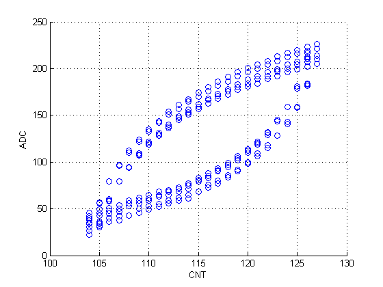
Figure 4: The raw plot that we got from our potentiostat.
Conclusions
Overall we believe that this project was a success; we were able to present a working potentiostat capable of performing cyclic voltammetry according to user-inputted parameters. The start and stop voltage, as well as the number of scans can be input by the user using a keypad and the hyperterminal. The sweep is performed and the data is collected by the ADC and printed to hyperterminal. The unit can be run multiple times and does not have to be reset between scans.
If we were to do this project again, we would have spent less time working with first DAC (MAX5354), because in the end we had to sacrifice some other functions due to time restraints. Additional functions that we originally hoped to include were internal ADC to current value conversion, better resolution, and building the unit on a custom board and packaging it for use. Due to time constraints we were forced to use an STK-500 and whiteboard for our demo, and did not get the chance to solder any of the parts.
We used many examples presented on the ECE 4760 website as basis for our code, especially the SPI example. There are no legal or intellectual property considerations, or any standards of concern in this project.
We followed the IEEE Code of Ethics as addressed below:
-
to accept responsibility in making decisions consistent with the safety,
health and welfare of the public, and to disclose promptly factors that might
endanger the public or the environment;
We took precautions while working in the lab to ensure the safety of ourselves and others. All chemicals used for testing were handled using the proper precautions.
-
to be honest and realistic in stating claims or estimates based on available data;
We were forthcoming with our data and the shortcomings of this project. -
to reject bribery in all its forms;
We rejected all bribes. -
to improve the understanding of technology, its appropriate application, and potential consequences;
We worked to develop a device that could be used to further the understanding of biological processes in remote settings not typically accessible with large laboratory equipment. -
to maintain and improve our technical competence and to undertake technological tasks for
others only if qualified by training or experience, or after full disclosure of pertinent limitations;
We fully disclosed the shortcomings of our device. -
to seek, accept, and offer honest criticism of technical work, to acknowledge and correct errors,
and to credit properly the contributions of others;
We seeked input from professors and other students in the course of this project.
-
to assist colleagues and co-workers in their professional development and to support them in following this code of ethics.
We were happy to help colleagues and co-workers throughout this project.
Appendices
Appendix A: Budget and Parts List
| Part | Source | Unit Price | Quantity | Total Cost |
|---|---|---|---|---|
| Total | $63.18 | |||
| STK 500 | ECE 4760 Lab | $15.00 | 1 | $15.00 |
| ATmega644 | ECE 4760 Lab | $8.00 | 1 | $8.00 |
| Power supply (± 12V) | ECE 4760 Lab | $5.00 | 1 | $5.00 |
| 2 pin flat jumper cables | ECE 4760 Lab | $1.00 | 4 | $4.00 |
| Keypad | ECE 4760 Lab | $6.00 | 1 | $6.00 |
| 16 MHz crystal | 4760 Lab | $1.05 | 1 | $1.05 |
| White board | ECE 4760 Lab | $6.00 | 1 | $6.00 |
| 1kΩ Resistors | Digikey | $0.09 | 12 | $1.08 |
| 10kΩ Resistor | Digikey | $0.09 | 1 | $0.09 |
| 10kΩ Potentiometers | ECE 4760 Lab | $0 | 3 | $0 |
| LM148, quad op amp | Digikey | $7.98 | 2 | $15.96 |
| AD7303, DAC | Bruce Land | $0 | 1 | $0 |
Appendix B: Schematics

Figure 5: Schematic of our project.
Appendix C: Code Listing
4760_final.c
uart.h
uart.c
raw data
plot using Matlab
Appendix D: Distribution of Tasks
- DAC setup
- ADC
- UART
- Report
Both
- Op-Amp circuitry
Elliot Friedman
- Keypad
Alexander Hartoto
Reference
A.V.Gopinath and D. Russell, "An Inexpensive Field Portable Programmable Potentiostat", Chem Educator, 2006. pp 23-28.
Datasheets
Atmel ATMega 644 Microcontroller
Analog Devices AD7303 (two channel, 8-bit DAC)
National Semiconductor LM148 (Quad Op-Amps)
Vendor
Atmel
Analog Devices
Digikey
National Semiconductor
Utilized Libraries/Code Borrowed
keypad debouncing
uart.c
uart.h
Background Sites/Paper
Serial Peripheral Interface (SPI) Mega644/GCC
Acknowledgements
Many thanks to Bruce Land and all ECE 4760 TAs for their help throughout the semester. We would also like to thank Joerg Wunsch for this uart codes.