Introduction
High Level Design
Program Design
Hardware Design
Failure Analysis
Results
Conclusions
Appendice
Reference
ECE 4760 : Designing with Microcontroller
Introduction
When we were little, remote controllable toys such as RC car always fascinated us. The idea of controlling a moving object from distance had been fabulous for us. Even more, controlling an object in the air would have been even better. The purpose of our project is to build a helium lifted airship with propellers for controlling motion that is controllable from distance by use of radiofrequency communication. First, we started by building building-blocks of the whole program simultaneously building the hardware block necessary to test the program blocks. After building the sub-programs(motor control, radiofrequency transmission and reception, analog to digital conversion), we assembled all the subprogram. Our major difficulty was due to the fact that we overestimated the lifting power of helium. Thus we had to reduce weight radically to try to lift up our ship.
top
High Level Design
Project Rationale
The project was conceived first by watching a bird flying. By looking at such freedom the bird possessed, we immediately realized that there is nothing more impressive than being able to fly. Nonetheless, our budgets were limited and also our times were limited, so that we could not go for F-16 fighters. Hence the compromise was made to make an airship, controlled through a wireless controller, and with a helium balloon to aid the lifting force.
Math Background
There are two major math background needed for this project: antenna theory and the helium lift theory.
(1) Antenna Theory
For the wireless control, a radio frequency (RF) transceiver was implemented. The operation of such transceiver is governed by the antenna theory which is described briefly in this section.
Recall two of the Maxwell’s equations:
|
Now, implement the scalar and vector potentials:
Then, the Faraday’s law in the equation (1) becomes
Using the vector identity that the curl of gradient is zero,
Combining the equation (5) and the vector potential part of the equation (3), and combining them with the Lorentzian Gauge, we can obtain:
Solving the equation (6) gives the vector potential A, and then H field and E field can be retrieved from the vector potential A.
Without further due, the above equations can be manipulated to show how the E&M can be coupled to the current density, and vice versa.
The most important parameter in antenna theory is the antenna gain, especially which of the Hertzian dipole which is similar to the antenna implemented in this project
The pre-factor is rather less of importance; rather, what is important there is that the angle has to be 90 degrees in order for the maximum gain, and there for alignments of the transmitter antenna and the receiver antenna become important.
The quarter wave antenna has a single wire in one end but it behaves as a dipole antenna with the imaginary antenna part on the other end. This in effect behaves as a half-wave dipole antenna with the half the power. For the quarter wave antenna, it is ok to have the antenna length to be the multiples of the quarter of the wavelength used for the wireless communication. However, multiple of a fraction of the quarter wavelength could bring destructive effect to reduce the transmission efficiency of the transceiver.
(2) Helium Lift Force
Helium weighs 0.1785 grams per liter while the air weighs about 1.25 grams per liter. Due to the difference in the helium weight and the air weight, about 1 liter of helium can lift about 1 gram from the following equation:
|
Logic Structure
The main idea of the airship is that the helium balloons are not capable of lifting the motor/MCU module just by little bit. Therefore, when the lifting motors are turned on, the thrust from the two motors are enough to generating enough lifting force to bring up the airship. In addition, there are two motors that put thrust in the sideway. By changing the ratio of speed between the two side motors, the airship can rotate either left or right. These lift motors and directional motors enable the three dimensional control over the airship.
The control of the airship is done through remote controller. The controller, which is controlled by three potentiometers, sends RF signals to the airship. In turn, the airship receives the signal – through an antenna if necessary – to obtain information on how to control the fans (motors). By controlling the motorized fans on the airship, one can manipulate the directionality and acceleration of the airship navigation. The block diagrams for the functionalities described above are shown in the figure 1 (for the transmitter operation) and figure 2 (for the receiver operation) below.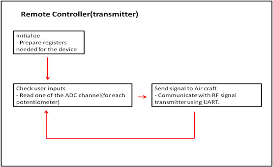
Figure 1: Block Diagram of the Transmitter
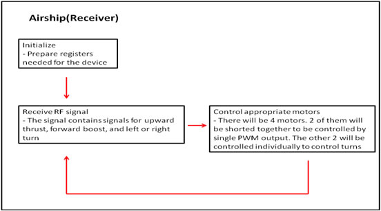
Figure 2: Block Diagram of the Receiver
Hardware Compromises
Since the airship is lift using helium balloons and more balloons are need to lift more weights, there is an intrinsic tradeoff between the size of the airship and the size of the motor. Though bigger motors can exert more torque, hence lift more weight, it might require additional balloons because the bigger motors are much heavier. Also, as more balloons and bigger motors are used, they add to extra cost, hence there is trade of between such items and the cost of the project.
Standard Compliance
The airship complies IEEE safety standard to avoid any possible hazard. The propeller is in soft plastic to avoid any cutting injuries. In addition no high power will be used for the safety reason as well.
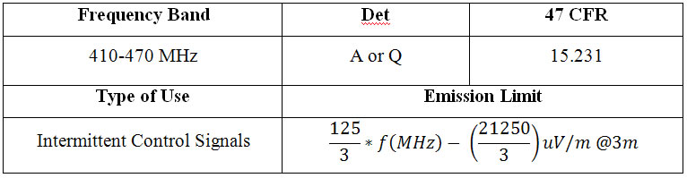
This project does meet the regulation imposed by FCC, which is shown in Table 3 below, to incorporate with legal considerations.
Table 1: FCC Regulation for RF
top
Program Design
Transmitter
(1) TIMER0
Mega644 has TIMERX modules which increase at user specified rate independently from program execution. The program has number of tasks to be run. In order to control the timing of each tasks, we used TIMER0 to generate 1 millisecond time base. During initialization routine, we set the CS<02:0> bits in TCCR0B register to 011 to change prescaler to 1:64, OCIE0A bit in TIMSK0 register to 1, and OCR0A register to 249 thereby making TIMER0 interrupt every 250 timer count. Thus, we were able to generate 64/16000000 * 250 = 0.001s time base. During TIMER0 compare match interrupt service routine, we incremented timer for each of the tasks. Thus, we were able to make the task for transmitting data and the task for taking analog to digital conversion data every 50ms. During initialization, we made sure that the two timing variables for our tasks didn’t time out at the same time by initializing one timing variable to be 0 and the other timing variable to be 25.
(2) Analog to Digital Conversion
Mega644 board has an analog to digital converter(ADC) which has 8 software multiplexed channel with prescalable clock. The analog to digital converter converts the analog value linearly and stores the result in 8bit or 10bit form, which can be read by user. The transmitter board takes in user-input through analog values from three potentiometers. As reference voltage, AVdd was used. Each potentiometer was to control upward thrust, forward thrust, and turn. Turning up the potentiometers for upward and forward thrust, would make the propeller in the airship turn faster giving it more power. The third potentiometer was designed to work like a car handle. Turning the potentiometer knob left would make the airship turn left. Similarly, turning the potentiometer knob right would make the airship turn right. To implement the analog to digital conversion from three different sources, we had to manipulate analog to digital converter channels. Thus we changed MUX4:0 in ADMUX bit to change channel before each conversion to take in three different data from three different sources. For ease of programming we set the ADLAR bit in ADMUX to one thereby making the processor right adjust the result. Right adjusting the data made us able to use the value stored in ADCH register for eight bit analog to digital conversion result. Since the airship we designed would be very large compared to the restricted power we have due to weight constraint, we figured that full 10bit resolution for analog to digital conversion was unnecessary. Thus we only took the upper eight bit by taking the value of ADCH register. Of course, we had to set the ADEN bit in ADCRA register to enable the analog to digital conversion. At first, above register configuration for the analog to digital converting peripheral did not produce correct converted value. After trying many times to make it work by changing various other registers, we figured out the reason that the converter didn’t work was that the clock input to the analog to digital converter inside the microcontroller was too fast because we were using 16Mhz crystal without prescaler. The clock speed was too fast for the analog to digital converter to charge up. Thus we had to change the prescaler to 1:128 to give the analog to digital converter enough time to convert. Lastly, we made the digital I/O function of the PORTA(which should be used for analog to digital conversion port) by setting DIDR0 register to value 0xFF. Also, we changed the port direction of PORTA to inputs by changing DDRA register to value 0x00. The correctly setup analog to digital conversion routine was carried out every 50 millisecond. In the routine that takes the analog to digital converted user input, 1) we changed analog to digital channel by changing ADMUX register, 2)initiated conversion by setting ADSC bit in ADCSRA register to one, 3) waited for the conversion to finish by monitoring ADIF bit in ADCSRA register, and finally read the value of ADCH register. We did the above step three times to take in three different data from three different sources. The converted value ranged from 1 to 255 since we used only eight bit result. For upward and forward data, 1 meant least power and 255 meant maximum power. For Left or Right handling, the value of 1 meant turning the handle to the left fully and the value of 255 meant turning the handle to the right fully.
(3) Data packaging
For radiofrequency transmission and reception, we had to allow the radiofrequency receiver to adjust its gain and keep it stable by keeping the DC bias of the bytes sent constant. In other words, the number of ones and zeros in each byte sent had to be the same for each byte we sent. If a byte consisting of all zeros were sent for prolonged period of time(in microcontroller sense) the receiver would turn up its gain because it will think that it is receiving no signal. Turning up the gain to high would make the receiver very susceptible to noise especially in lab environment full of electronic equipment. On the other hand, if we send a byte consisting of all ones for prolonged period of time, the receiver would turn down its gain since it thinks that it is receiving noise making it hard to detect the real signal. Thus we decided to sent one nibble at a time(Low byte and High byte). Using function data_packager_L and data_packager_H, we balanced the number of ones in each nibble by attaching the negated version of mirror of the nibble to be sent. For example, for nibble 1101, we attached 0010 to make a byte 11010010. For low nibble, we put the original nibble on the lower nibble position and attached the negated nibble on the higher nibble position, and for high nibble we kept the original nibble on the high nibble position and attached the negated nibble to the lower nibble position for programming simplicity in the receiver side. Thus, the three bytes we wanted to send(upward, forward, and Left or Right) was divided into 6 nibbles balanced by their negated values.
(4) Transmitter and Receiver Syncing
For radiofrequency transmission and reception we used RCT/R 433 by Radiotronix. The module uses 433Mhz as carrier frequency. . Before sending the actual data we wanted to send, we first wanted to allow receiver to adjust its gain. Thus, we sent bit balanced byte(0xAA) 5 times to allow the receiver to adjust is gain appropriately. Also, because some of the other groups were using the same parts(using same carrier frequency) we had to have means of making sure that the data received by the airship was actually the data sent from our transmitter and not somebody else’s. After sending gain adjust bytes, we sent 3 bytes(bit balanced) which we called sync bytes(0x35, 0x69, and 0xAC) to sync with the receiver. On the receiver end, the software simulated state machine kept track of each byte received and it recognized our data only after the three sync bytes are received in order. In other words, only after sending the gain adjust bytes and “Sync byte” we sent the actual data.
(5) UART Transmission
For communication between the radiofrequency transmitter and the microcontroller, we used the built in USART module in the mega644 with asynchronous mode at baud rate of 2400. During initialization routine, we set the TXEN bit in UCSR0B register bit to 1 to enable UART transmission. Also, we set the UBRR0 to 416 to set the baud rate to 2400. Finally we set the UPM0<1:0> bits in UCSR0C register to 11 to set the UART module in odd parity mode, and USCZ<1:0> to 11 to make the character size eight bit. To send a byte to a radiofrequency transmitter from the MCU, first we made sure that the UART transmit buffer was empty by checking UDRE0 bit in UCSR0A register. Once the transmit buffer was empty, then we wrote byte to UDR0 register. Then the data in the transmitter buffer was sent to shift register to be finally sent to the radio frequency transmitter.
Receiver
(1) UART Reception
For communication between the microcontroller and the radiofrequency receiver, we used built in UART receiver module. During initialization routine, we set RXCIE bit and RXEN bit in UCSR0B to one to enable UART reception and interrupt. Also we set the UBRR0 register to 416 to match the baud rate with the transmitter. Finally we set the UPM0<1:0> bits in UCSR0C register to 11 to set the UART module in odd parity mode, and USCZ<1:0> to 11 to make the character size eight bit to match the communication protocol of the transmitter. As explained above, transmitter first sends five gain adjust bytes and three sync bytes. In UART reception interrupt service routine, the program keeps track of each state(gain adjust stage, sync stage and data reception stage) to make sure that the data we received in airship is the correct data that we actually sent from the transmitter. The six nibbles received in this way are then sent to data_unpackager which combines two nibbles to produce the byte that we originally wanted to send.
(2) Motor Control
The most important aspect of our receiver board design is the motor control. For motor control, we use two timers, TIMER0 and TIMER2 for PWM output. In order to use the PWM peripheral, we set COM0A<1:0> in TCCR0A register to 10 to use OCOA pin as the noninverting PWM output to drive upward motor. The OCOA pin will be high as long as the value of the TIMER0 is lower than OCROA register. We wanted simple fast PWM mode so we set the WGM<1:0> bits in TCCR0A register to 11. In previous lab regarding digital tachometer(lab4 in ECE 4760 at Cornell) we noticed that the frequency of PWM output which controls motor was important because frequency that was too high would not pass across the optoisolator and the frequency that is too low would give erratic response of motor. Thus, we set the prescaler of the TIMER0 and TIMER2 to 64 to make about 1Khz PWM frequency, the same frequency we used For TIMER2, we set the COM2A<1:0> bits and COM2B<1:0> bits to 10 to use OC2A and OC2B pins as PWM output for controlling left motor and right motor. Through radiofrequency communication, we receive three bytes(“upward”, “forward”, and “Left or Right”) which corresponds to the upward thrust, forward thrust, and left or right turn. Upward byte goes directly into OCR0A register for direct translation of upward thrust and the data sent from the transmitter to control the duty rate. The duty rate for the motors that provides forward thrust is calculated by combining the latter two bytes sent by the transmitter. The duty rate for the left motor is determined by “forward”/2 plus (255 - “Left or Right”)/2. The duty rate for the right motor is determined by “forward”/2 plus “Left or Right”/2. Thus, for left and right motor, half of the thrust depends on “forward” byte and the other half depends on “Left or Right” byte. The calculated duty rate “Left” and “Right” is then written to OCR2A and OCR2B register respectively. Please note that we chose the above three PWM output pins for soldering ease. Without that consideration, we could have chosen any three PWM output pins from all six PWM output pins to drive motors. Lastly, our radiofrequency transmitter and receiver pair had only limited range, we needed to have safety mechanism for retrieving our airship in case the airship lost and the transmitter lost contact. Thus, we kept another timer, to count the time from the last reception of data arrays. If the airship did not receive for prolonged period of time(in microcontroller sense), it was programmed to turn off all of the motor. That way, we would be able to retrieve the ship even if it loses connection because it would fall slowly by gravitational force.
(3) Watchdog Timer
Due to the nature of our project that used the actuator that generated heavy noise, even with optoisolation, and the fact that we had to use small lithium battery(which turned out to be very unreliable) to power the MCU, we had to make sure that the system was self correcting in case of runaway code, probably due to corrupted program counter. Thus, we decided to use watchdog timer built inside the mega644 MCU. The watchdog timer is just like any other timers that we used for controlling the motors except that it is clocked from different source and it resets the processor when it expires. Thus, the watchdog timer has to be reset periodically to prevent the unwanted processor reset. The watchdog timer is very useful because when the code runs away, it is very likely that the program won’t reset the watchdog timer on time making the timer reset the CPU. In order to use watchdog timer, we set the WDE bit in WDTCSR register to one to enable watchdog timer. Also, in order to change the time out period for watchdog timer to the value we want, we had to first set WDCE bit in WDTCSR register and then change WDP bits in WDTCSR register. We set the WDP bits to 101 to make the watchdog timer time out at 0.5 second. However, even with watchdog timer, the system is not fail proof. For example, if the program enters an infinite loop that constantly clears watchdog timer, it can never recover. Also, the hardware, not the software, condition persists, it is very likely that the processor will reset constantly.
Hardware Design
Radiofrequency Communication
Our radio frequency transmitter transmits when the input to the data pin(pin3) is logic high. However, the default state of the UART communication is logic high when no data is being transmitted. However, we didn’t want the transmitter to send signal always in order to save power. For inverter, we used very cheap and space saving configuration by using two resistor and a NPN transistor. The gate of the NPN transistor is connected to the microcontroller UART TX pin. When TX pin is high, it turns on the transistor thereby pulling the drain end of transistor to ground. When the TX pin is low, the transistor is off and the drain end of the transistor is pulled up to logic high. The antenna was designed to have the length of the quarter
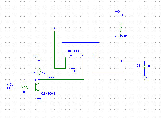
Figure 3: Radiofrequency transmission circuit
wavelength of the transmitted signal, about 17cm for maximum gain. The supply to the radio frequency transmitter was filtered using inductor which contains some resistance and a capacitor to make the supply voltage as stable as possible for optimum performance of the transmitter.
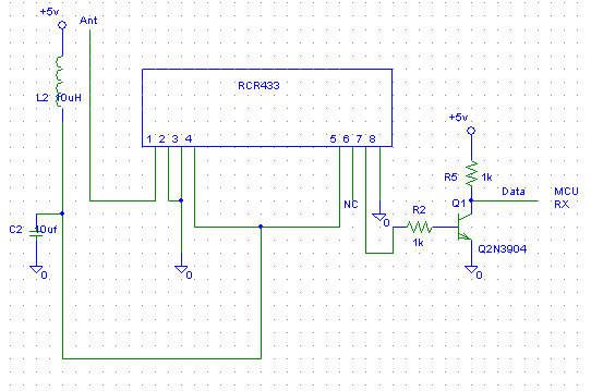
Figure 4: Radiofrequency transmission circuit
Similar to radiofrequency transmission circuit, we filtered the supply voltage with an inductor(which contains some resistance) and capacitor. This time, the data from the receiver is fed to the input of our inverter configuration. The MCU then takes data from the output end of our inverter. The data from the receiver needs to be inverted back because the original data was inverted in order to save power.
Motor Control
A motor normally generates electromagnetic noise that can possibly crash the program in microcontroller. Plus, the particular motor used would require a voltage higher than the voltage supplied to microcontroller. Thus, we had to use another power supply to power the motor. The bridge between the two system is the optoisolator 4N35. The positive end of the diode is connected to the PWM outputs of the MCU through a resistor, and the negative end to the ground. Thus, inside the 4N35 chip, when the MCU outputs high, the diode emits light.
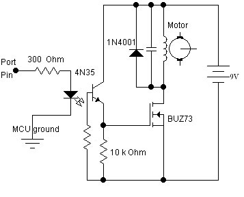
Figure 5: Motor Control Circuit
That light, is then captured by the phototransistor inside the 4N35 chip, and makes the transistor conduct. When the transistor conducts, the emitter side of the transistor becomes 9V and turns on another transistor(NMOSFET) to conduct, thereby powering the motor. As a result, the motor receives power only when the MCU outputs high.
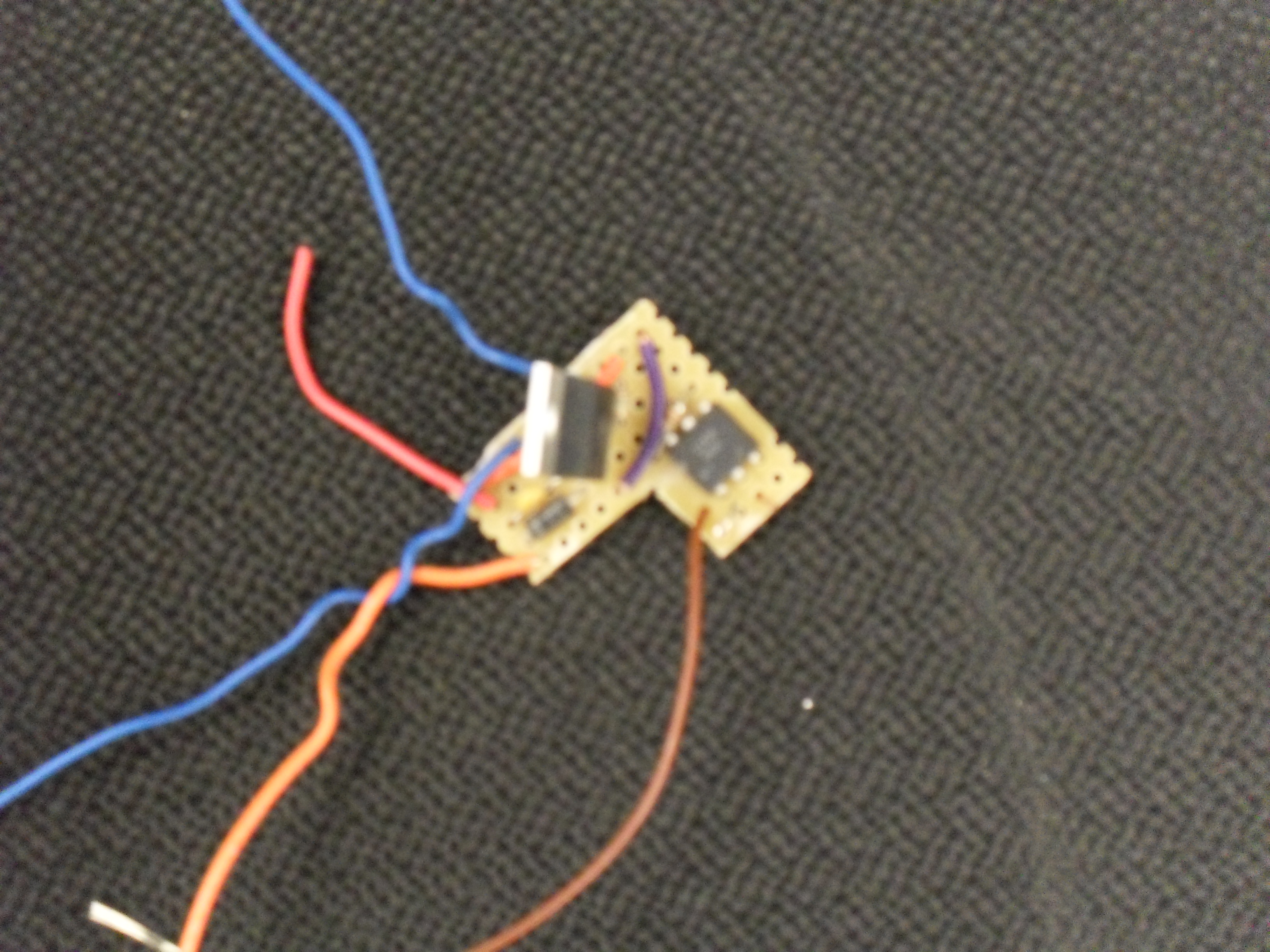
Figure 6: Motor Control
The speed of the motor is controlled by generating pulse width modulated signal from the MCU. The motor itself is a low pass filter with resister and capacitor buried inside. Thus, we can control the speed of the motor by varying the pulse width of the PWM signal. In parallel to the motor, notice we added a capacitor and a diode. A capacitor removes an ac noise and the diode absorbs a negative spikes from the inductor when the motor is suddenly unpowered, in order to protect the NMOSFET transistor from breaking.
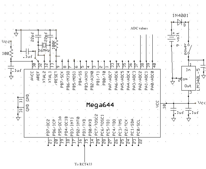
Figure 7: Microcontroller Board Circuit of Transmitter
Our microcontroller design uses 16Mhz crystal with 5V power supply from LM 340L regulator output. To the regulator input, we used 9V battery. As long as the voltage at the input of the regulator is higher than 7.5V, we can get stable 5V from the regulator output. As a safety
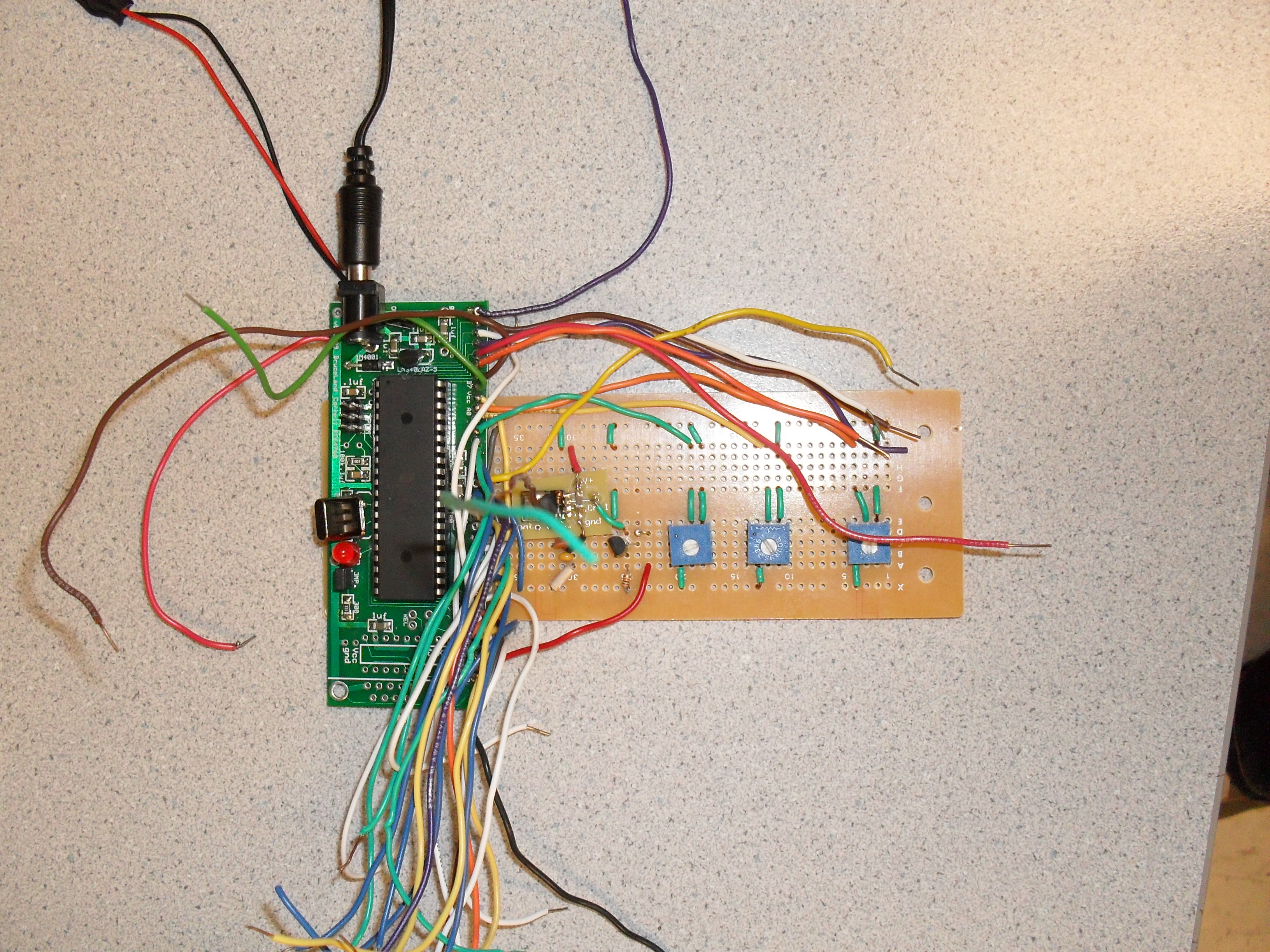
Figure 8: Transmitter
measure, we added a diode in front of the input of the regulator. The diode is there to block the backward voltage applied by mistake. To the ADC0, ADC1, ADC2 pin, the analog inputs from three different inputs goes in. The TXD pin of the MCU is connected to the data pin of the RCT 433.
Receiver Board
The receiver circuit is powered in exactly the same way as the transmitter circuit. However, the output line from OC0A, OC2A, and OC2B pin goes to the motor module to control motors. Also, the microcontroller receives data from RCR 433 through RX pin.
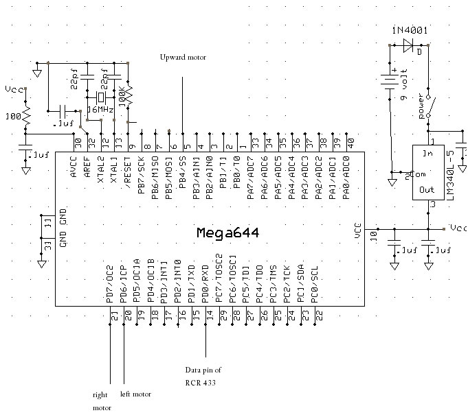
Figure 9: Microcontroller Board Circuit of Receiver
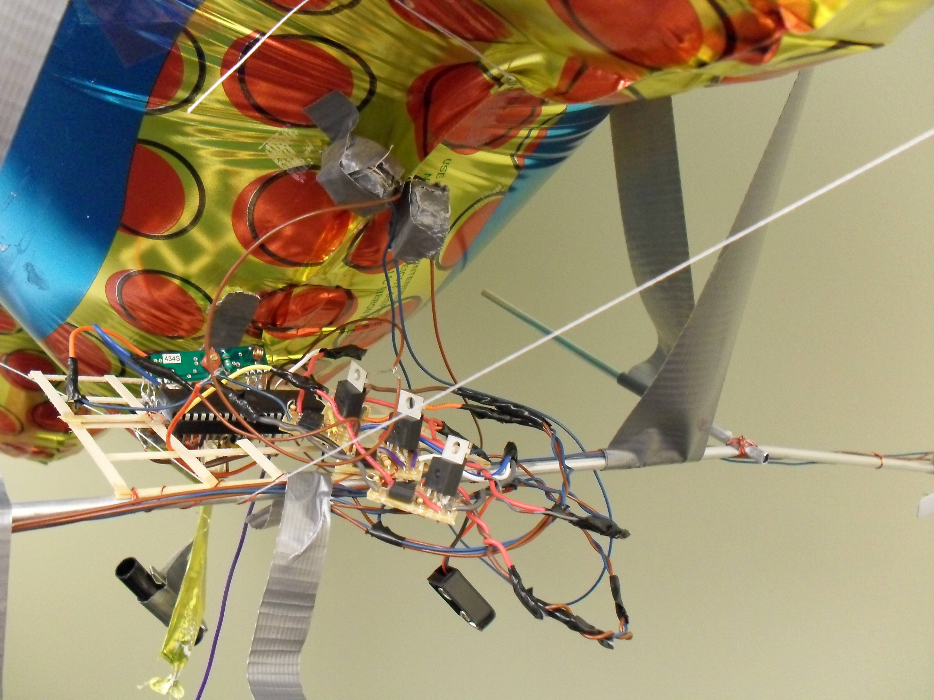
Figure 10: Receiver
Airship Exterior Design
The creation of the airship platform was fundamentally limited by the availability of the balloons. Because there was no balloon of the size required to lift the control module, many balloons were cascaded. The airship consists of the total of 7 helium-filled balloons:
Table 2: Antenna Length vs Wireless Communication Range
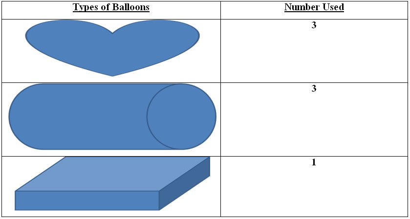
As a result, the balloons were stacked as shown below:

Figure 11: Balloon Module
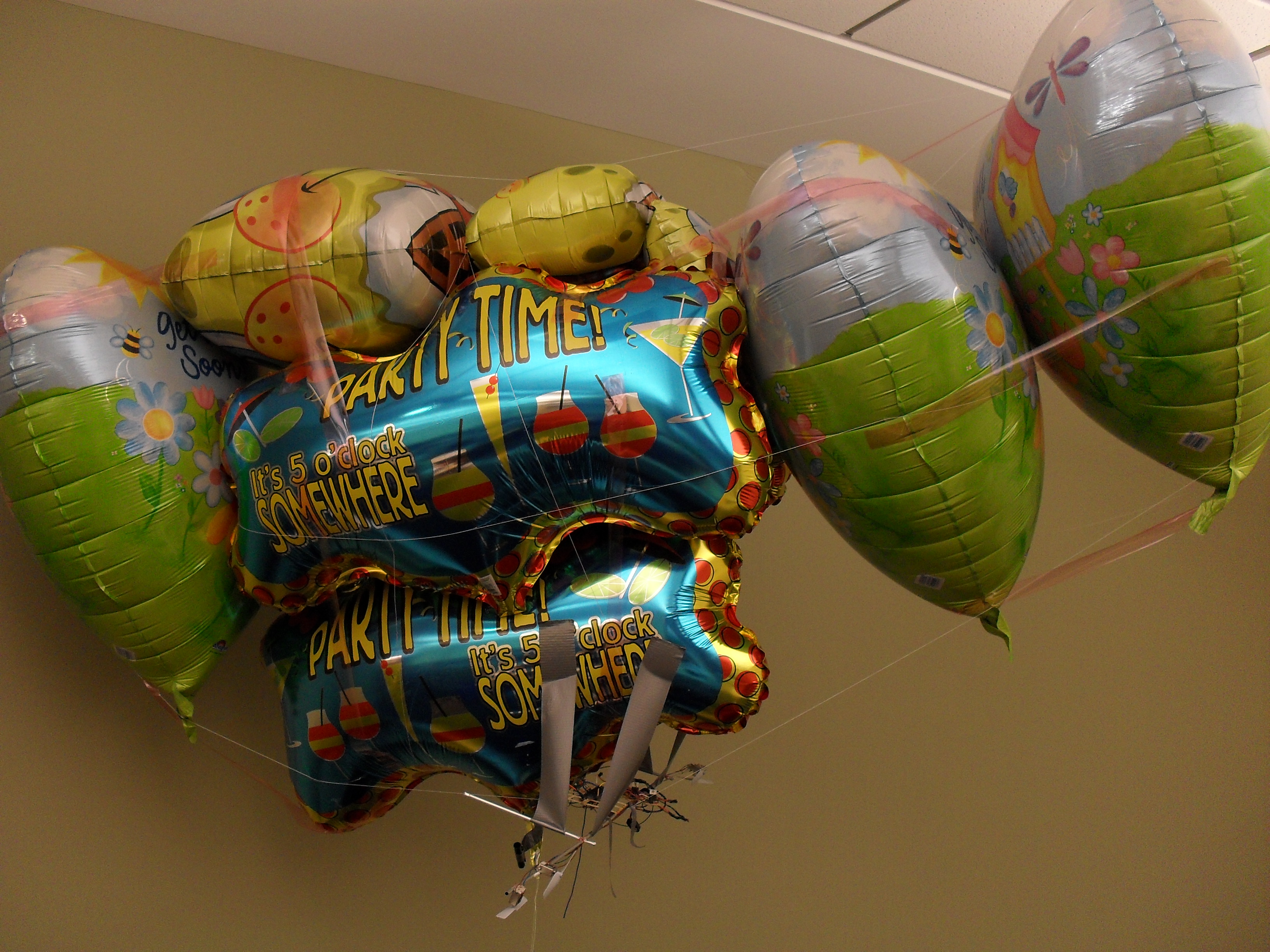
Figure 12: Balloon
Close to the center of mass in the balloon module, around the bottom-center of the balloon module, the control module including the motors were attached. The schematic of the control module is as shown below:
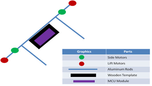
Figure 13: Control Module
Duct-tape was used to establish the connection between the side aluminum rods and the balloon module. The combined version of the airship is shown below:

Figure 14: Airship
top
Failure Analysis
Antenna for Wireless Communication
A use of wire to fulfill a function as an antenna was suggested in the specification document of the wireless transceiver. Nonetheless, at first, it was neglected. Furthermore, without the much knowledge on the antenna, initially no wire was connected to the wire end of the chip. It did transmit and receive signals, however, the efficiency was rather low – the wireless communication did not work for more than about 7 meters. Then, we put an antenna blindly, just hoping for the best, without realizing that the antenna put on was, accidentally close to the half of the quarter wavelength. Then the wireless communication barely worked, only in even a short distance of few meters. Then we came back to the antenna theory, and put on the quarter wavelength wire as an antenna and achieved almost maximum value shown in the specification of the wireless transceiver – 300 ft which is close to 100 meters. This was verified by moving the transmitter from one end of the Duffield hall to the other end of the hall.
Table 3: Antenna Length vs. Wireless Communication Range
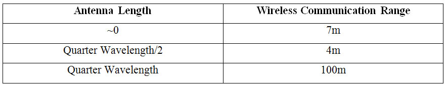
Another important feature to be noted was that the antennas at the transmitter and the receiver had to be aligned for the maximum gain. Initially, the two antennas were put close to orthogonal and the wireless communication did not work – as predicted from the antenna theory, in the orthogonal alignment, the receiver and transmitter did not ‘talk’. Only after the antennas were aligned parallel to each other, they started to communicate. It did not matter whether one antenna was pointing downward while the other was pointing upward or not. This was anticipated because the quarter wavelength antenna in fact behaved as the half wavelength dipole with the imaginary quarter wave antenna at the other end of the real quarter wave antenna (two quarter wavelength make a half wavelength dipole).
Batteries
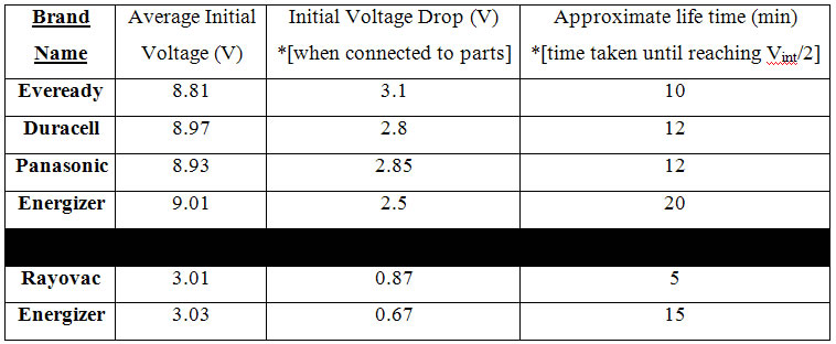
As mentioned previously mentioned, in order to allow wireless control over the airship, the motor was actuated through batteries. At first, we did not recognize the importance of the power-hour supported by a battery. Instead, we mistakenly took a voltage of a battery as a number that characterizes the battery. As a result, initially, small button cell batteries were tried. It was not too long after the trial when we realized that the small batteries could not drive the motors strongly enough as their power was limited. In operating a device that requires both high voltage as well as high current, the product of the two parameters, power, was important. Therefore, the 9 volt battery was used instead of the button cell batteries to drive the motors and indeed such motors offered much more strength to the motor drive. Therefore, 9-volt battery was used to control the four motors in the airship. In all the cases, only the Energizer batteries were used.
Moreover, it was interesting to note that different brands of batteries differed by a lot in terms of their power-hours. Though they seemed to run the motor the same in terms of the motor speed as long as their sizes were the same, brand-named batteries ran the motors for much longer than what the low-name batteries could do – almost twice as long.
Table 4: Battery Characteristics
After the motor battery has been replaced, there came the problem in controlling the motors through MCU. It was later found that it was also a problem with a battery as well. Initially used three serially connected three button batteries were not enough to keep the MCU running. The set of batteries had too small of power, and therefore, could not provide enough voltage and current for the regulator – 7.5 volts. At the end, serially connected five button cell batteries and serially connected five coin cell batteries were paralleled connected to be used for MCU in the airship in order to provide sufficient voltage and current for the motor control.
Noise
In order to reduce the mass of the airship module as much as possible, we tried to make a motor module without using an opto-isolator. Nonetheless, this resulted in a miserable failure as the inductive coupling-induced voltage spikes and noise created too much of disturbance for MCU to function properly. Essentially, the disturbance was large enough that the motors were not able
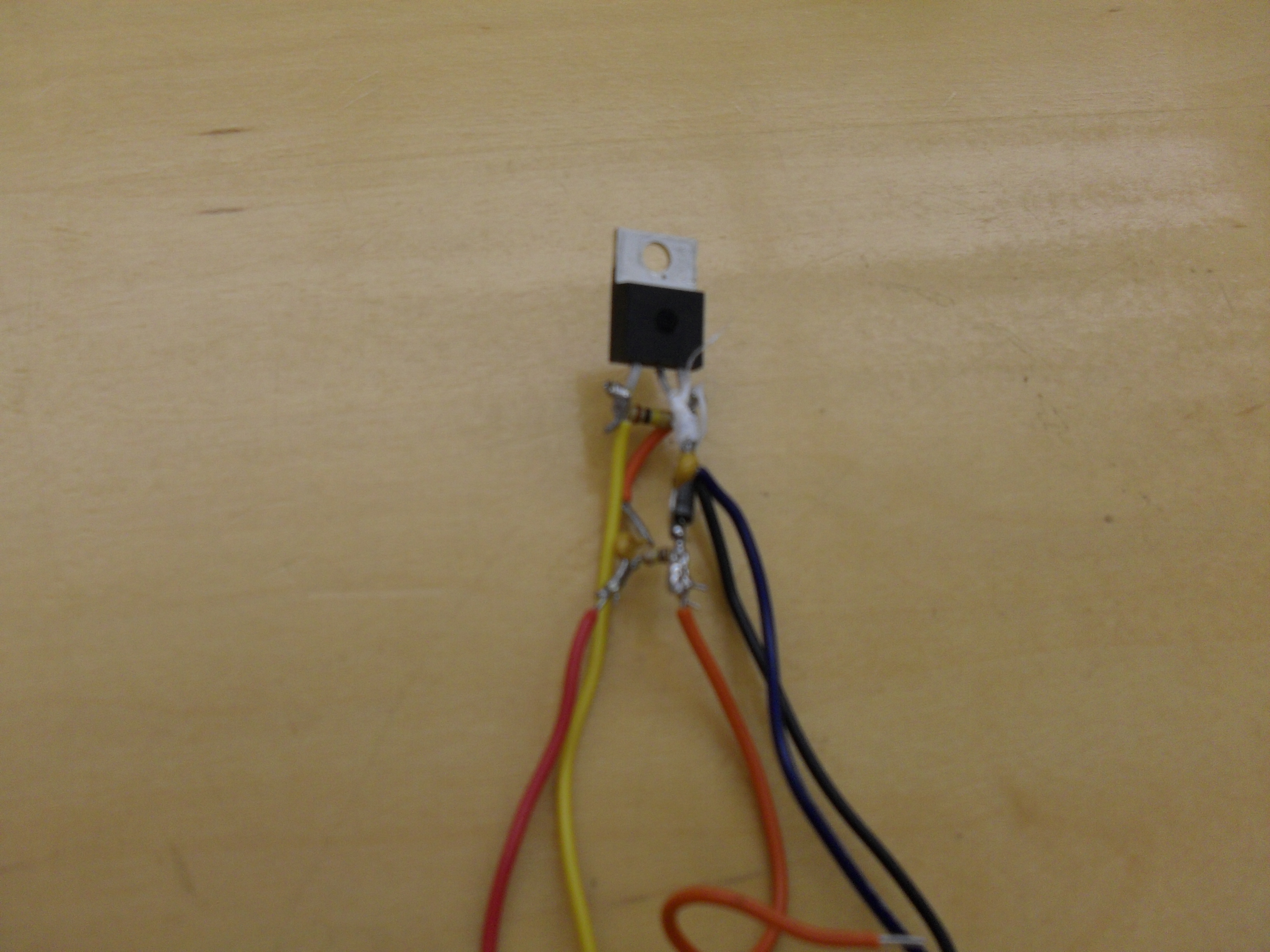
Figure 15: Failed Motor Module
to be controlled with the transceiver. Then we realized the importance of Prof. Land’s emphasis on the importance of the opto-isolator from Laboratory Four and included the opto-isolator in the motor module. Finally, the MCU could control the motors through the transceiver without a problem.
Helium Lift
At first, without the proper knowledge on the lift-force of the helium, we expected to be able to lift the airship module with one reasonable size helium-filled balloon – just from the experience that helium balloon flew upwards. However, we soon came to realize that was a huge mistake as the largest balloon could be purchased at Wegmans failed to lift even one 9-volt battery. It was later calculated that one liter of helium was needed for one gram of object to be lifted. As a result, many balloons were purchased and tightened together in order to create enough buoyancy force for the airship module.
top
Results
Speed and Responsiveness
Even if we reduced the weight of the parts mounted under the balloon as much as we could, we had to use very big volume of helium filled balloon to lift up the airship. Also, because of the weight constraint we could not use motors with big torque. Instead, we had to use mini motors that were light weighted. Thus, we only had limited amount of thrust for maneuvering airship. Therefore although the response to the radiofrequency transmission was very fast(almost instantaneous translation to PWM output), the speed of our airship was could not be very fast. Nevertheless, we were able to move the airship with reasonable speed as to make keep the controller entertained. The speed of the airship is best demonstrated in the video attached for demo testing.
Accuracy
For our purpose, the only accuracy that we needed to carefully consider was the accuracy of the sent data. Before we adjusted the antenna length to be quarter wave length of the carrier frequency, we had erratic transmission even when we moved the transmitter about 10 meters away from the receiver. However, after readjusting the antenna to quarter wave length, and
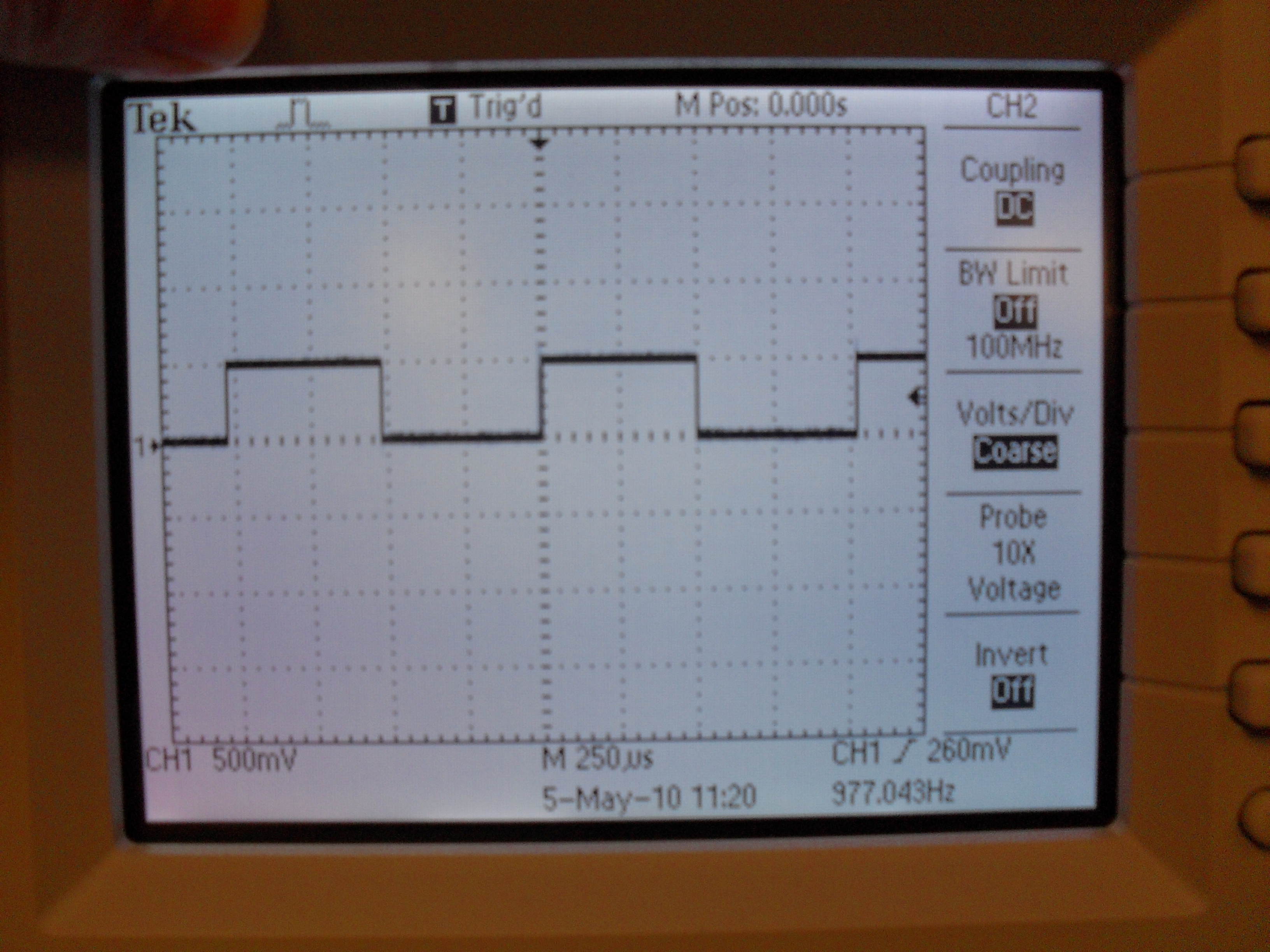
Figure 16: Oscilloscope Output of the Receiver End
making the sync byte arrays more restrictive, we were able to safely extend the range of the reception to about 100 meters without any corruption in data as specified in the datasheet of RCT/R 433.
Safety
The major safety concern we worried about was the receiver going out of control for various reasons. As described in software section, we designed the receiver program to turn off all the motors if no valid signal was received from the transmitter for prolonged period of time. Plus, we used the watchdog timer to monitor correct program execution. Nevertheless, if both of the safety measure failed, there could be little safety hazard because helium is not flammable and nontoxic. In earlier design phase, we also considered using hydrogen gas. However, we decided that that would be extremely dangerous although it would provide much more lifting force per volume. Thus, even if the balloon containing helium blew apart, there would be little hazard other than possible hearing loss, and heart attack from sudden noise. Thus, we advise people with heart problem avoid using the device we created.
Interference with Other People’s Design.
Because of the nature of our design, we could not help interfering with other people’s design. Our design uses a radiofrequency transmitter that sends strong radiofrequency signal to send information. Since we used the transmitter that was most common in our lab(donated by Radiotronix), all the other group who used radiofrequency receiver may have experienced problem due to signal interference caused by our transmission because most groups that were using radiofrequency communication were sending their data with the same carrier frequency. Even the groups that did not have the radiofrequency communication scheme might have experienced some erratic behaviors as devices that emit strong radiofrequency noise such as walky-talky can disrupt the microcontroller. Also, our motor generated tremendous amount of noise which might have disrupted other groups’ CPU.
Usability
The main part of the user interface is turning the knob on the potentiometer to adjust the thrust and turn. Users who have never controlled remote controlled device may have some difficulty controlling our airship because it requires constant spatial reorientation to control the airship facing different direction. For example, if the airship is facing away from you, you can use your intuition to turn the “left or right” knob to left to make the airship turn left. However, if the airship is facing toward the user, the user would then have to turn the knob to right to make the airship turn left from you. However, after a certain amount of practice(about 5 minute), most people can learn to control the airship and enjoy since the airship is very slow.
top
Conclusions
This project was successful in a sense that the airship met the specification initially imposed. For instance, it was possible to lift the airship as well as to change directions in both left and right. For improvements, the motor modules could be combined such that all the four modules can be built on one piece of board, which would save some extra room. Also, a better qualify regulator could be implemented to reduce the amount of batteries required for the MCU control, which could aid to reducing the amount of the helium needed. In addition, the more efficient propeller could be adapted in order to extract more lifting force from the motors.
The design conforms to the applicable standards in military or toy industry. It does not require much power, hence could be implemented as a spying tool, and it is also safe to be a toy. No code has been copied from another source but we wrote them ourselves. Since the technologies used are already well-known to the engineering society – motor control and wireless communication – there are rather small chances of getting patents out of this project. However, if we happen to use this tool to spy on other nations on issue – such as North Korea or Iran, the result could be publishable.
In terms of ethical considerations, first of all, the airship satisfies the demand of green trend which advocates for less carbon mono-oxide emission. Because it does not consume a carbon fuel, this airship is totally environmental friendly, emitting no carbon mono-oxide. In terms of the safety consideration, the propellers are small and made of soft plastics such that there is the minimal cutting hazard. In addition, the airship is operated at a very low power device in consideration for the safety of the general public. Such low power feature also coincides with the electronic engineering society’s emphasis on low power devices. This could be helpful to be implemented in the defense related missions where the low power is the key to the success of the mission. We accepted no bribes to this project which we are very proud of and planning to keep our work ethic up to the standard of IEEE. After all, this project was a sincerely great opportunity to expand our knowledge on electronics that we only learn through textbooks. We take prides in keeping up with state of art technologies in motor control and wireless communication and being able to find a suitable application for the composite of the technologies. Lastly, we also have graciously accepted the productive criticisms from the Prof. Land as well as teaching assistant, all of which added invaluable value to this project.
top
Appendice
A: Photographs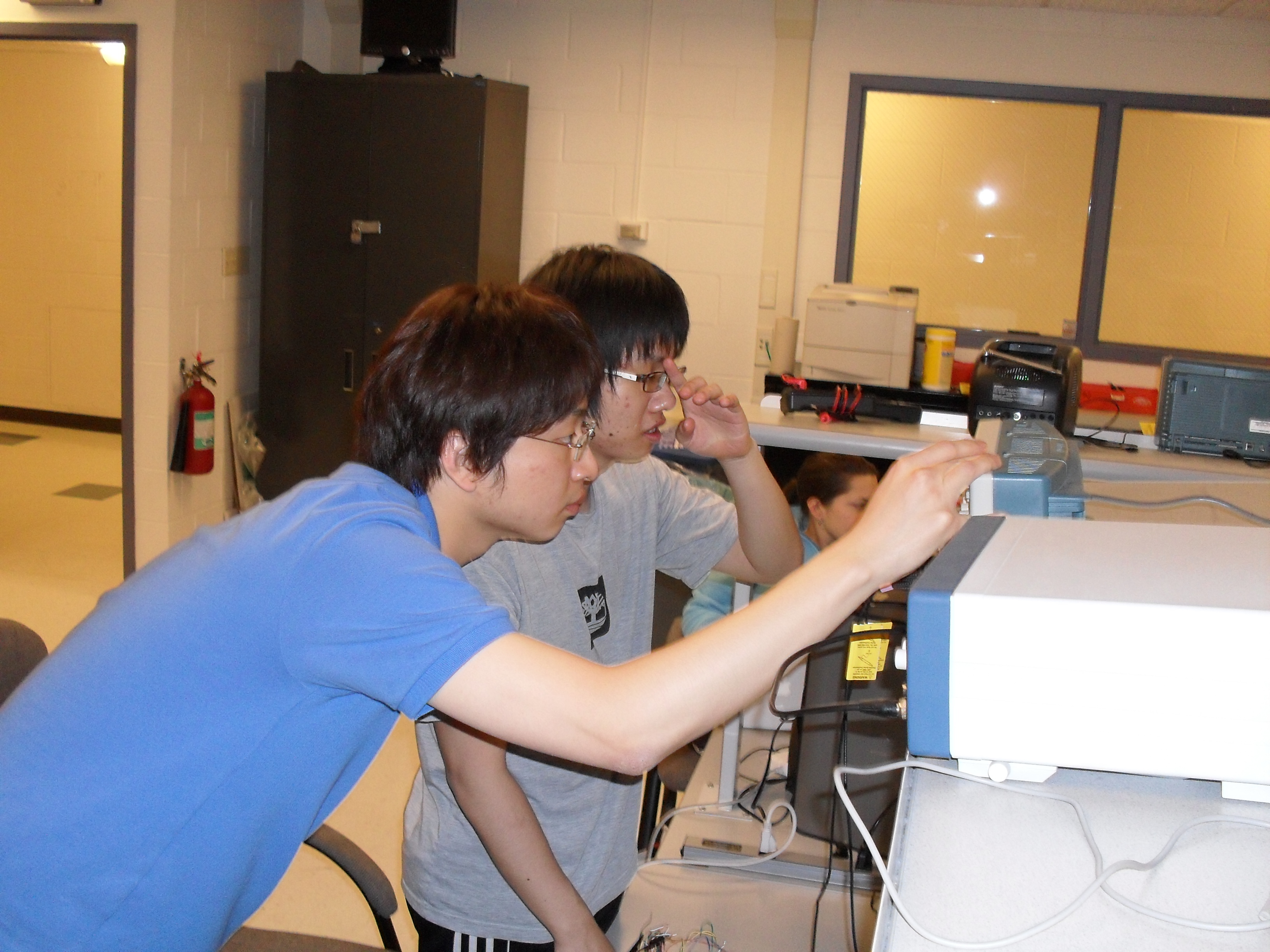
Figure 17: Debugging with Oscilloscope
![]()
Figure 18: Testing the Transmitter
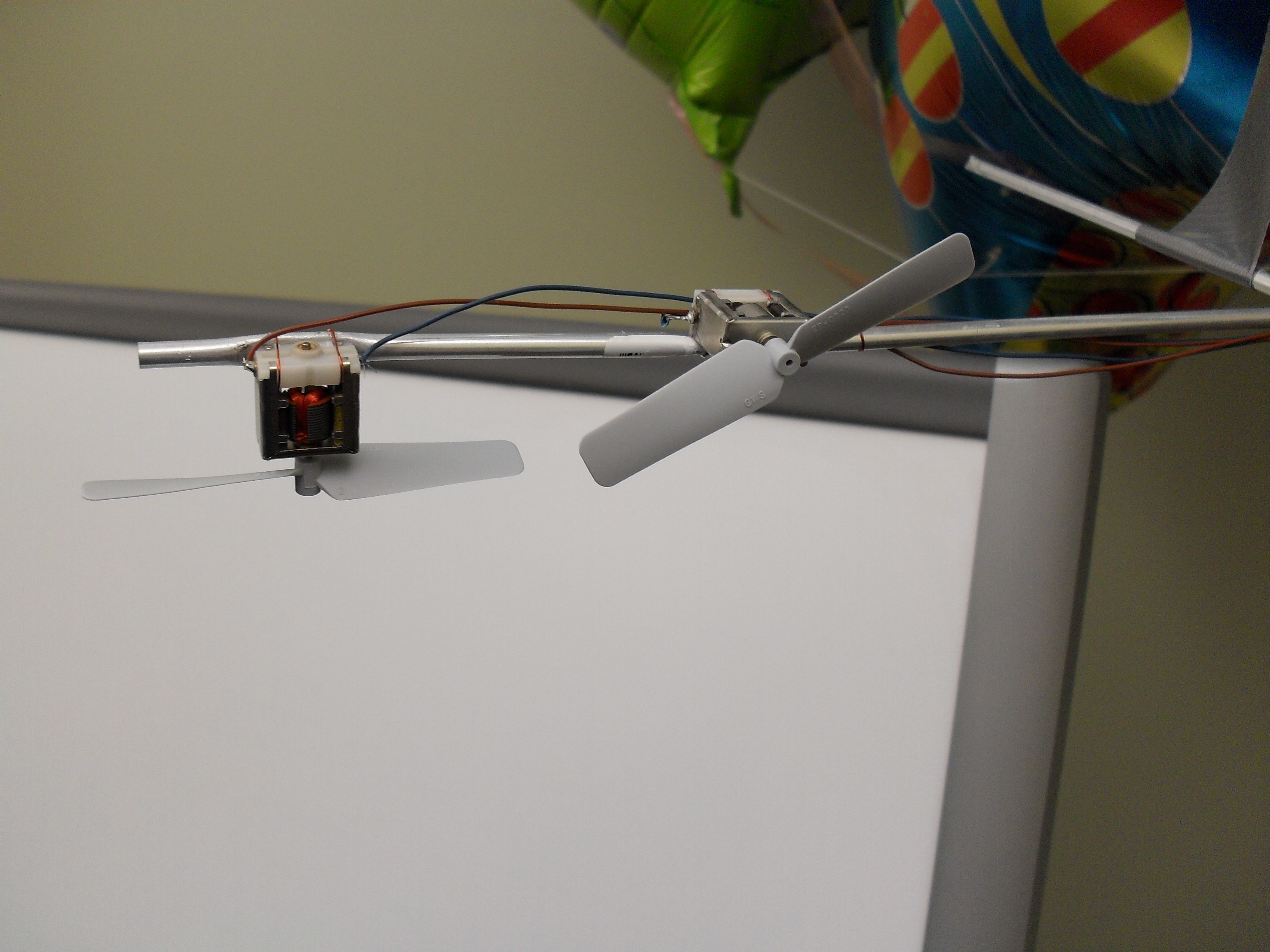
Figure 19: Motors on Shaft
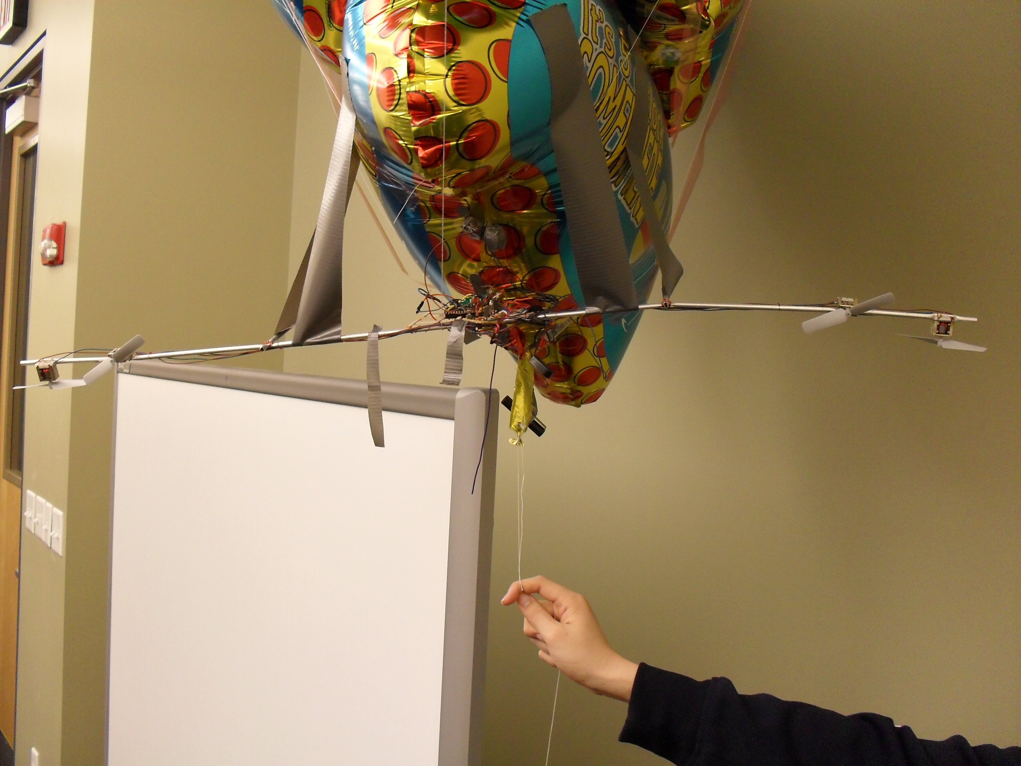
Figure 20: Motors and Shaft Structure
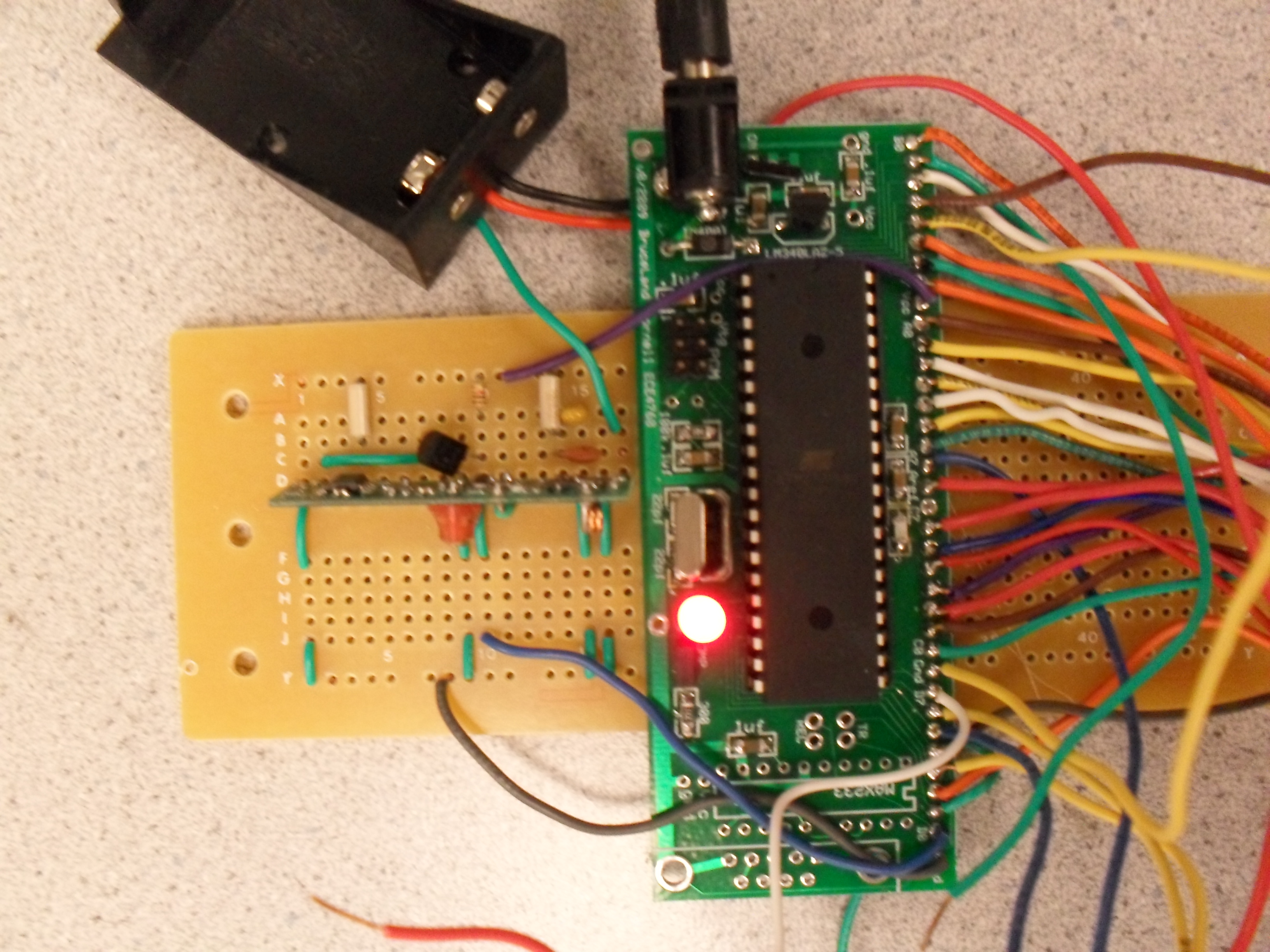
Figure 21: Receiver for Testing
B: Program Documentation
(1) Transmitter
Def_var.h - Contains all the variables and definition needed for transmitter program.
Data_packager.h - Divides the byte to be sent into two nibbles each, and balances the nibbles.
Initialize.h - Initializes TIMER0, TIMER2, UART, and AD conversion. Also sets the initial value for each parameters
Take_data.h - Converts the three analog input to digital value to be sent using AD converter.
Transmitter.c - Contains the main function.
(2) Receiver
Def_var.h - Contains all the variables and definition needed for transmitter program.
Data_unpackager.h - Combines lower nibble and upper nibble to make a byte.
Initialize.h - Initializes TIMER0, TIMER2, UART. Also sets the initial value for each parameters
RX_ISR.h - Contains interrupt service routine for UART receive interrupt.
Receiver.c - Contains the main function.
C: Cost
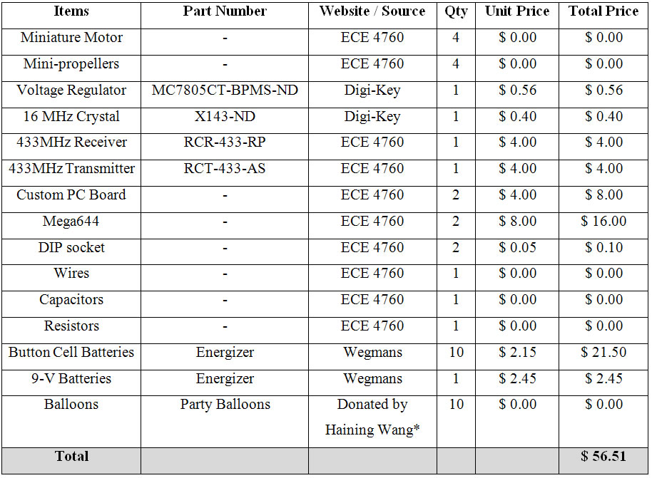
* Haining Wang who recently had a birthday party graciously donated his balloons for this scientific research.
D: Schematics
RF Transmission Circuit - Interface between a microcontroller and RCT433
RF Reception Circuit - Interface between a microcontroller and RCR433
Motor Control Circuit - Controls a motor through an opto-isolator
Transmitter Board Circuit - Connections around transmissmitor MCU
Receiver Board Circuit - Connections around receiver MCU
E: Task Breakdown
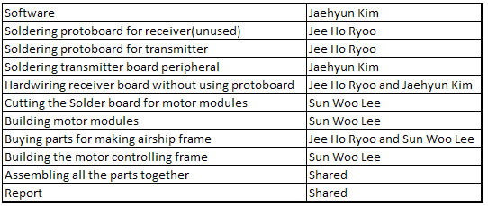
top
Reference
Datasheets
Atmel ATMega 644 Microcontroller
Radiotronix RCR-433 RF Receiver
Radiotronix RCT-433 RF Transmitter
Code and Design Examples
ECE 4760 Lab 4
Background Sites
Wireless FCC Reguilations
Acknowledgements
We would like to thank Bruce Land for instructing core concepts in lectures, which led us to successfully complete the final project. Also, his feedbacks on our project throughout the semester have helped us to take more innovative and challenging approaches. In addition, we would also like to thank Jeff Melville for helping us out throughout the semester in the lab. His comments on the final project proposal has led us to build the physical airship earlier than our scheduled date, which led us to find errors described above and made us to complete the project before the deadline.
top