Heart Rate Display LED T-Shirt
by Vivian Jang (vij2) and Nick Lee (nsl7)
Introduction
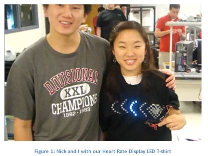
We have designed and built a LED t-shirt capable of displaying the heart rate of the wearer via a pulsing LED heart. Largely, our project consists of two components: the plethysmograph and the LED display.
How we came up with the Idea
We had thought up the idea of a heart rate display led shirt when we came across the LED shirt manufactured by Erogear©.
Erogear sells customized wearable led displays over their website at erogear.com.
One of the possible designs offered iss the one shown in Figure 2.
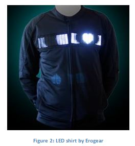
In this design, the LEDs are lit up in a shape of a heart and propagated across the wearer´s chest. After encountering this product, we had thought it would be incredible for the LED display to actually display the wearer´s heart rate. As far as we are concerned, the original idea of the propagating heart on a led display is copyrighted by Erogear.
High Level Design
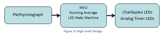
As previously mentioned, the project is divided into two subsections: the plethysmograph and the LED display. A plethysmograph is a device that senses the change of volume in an organ. For our purposes, we use an infrared light emitter and receiver to sense the change in the amount of blood in an extremity such as a finger or ear lobe. As for the LED display, individual LEDs that would be controlled by the microcontroller are manually wired into a shirt. At the suggestion of Professor Land, we looked into charlieplexing so that we may control the many LEDs we have with a minimal number of port pins of the MCU. Realizing that the majority of the LEDs were used only to produce a propagating effect, we decided to a string of analog timers which would markedly cut down the number of pins we would have to use otherwise. Figure 3 shows the basic flow of how our project works.
Plethysmograph
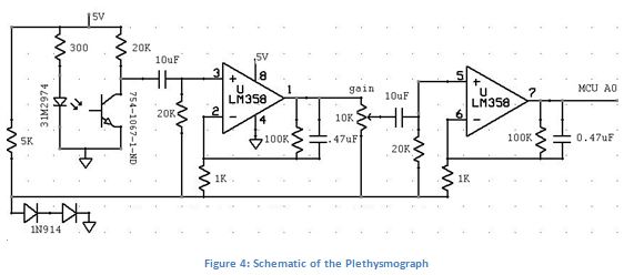
Fortunately, Professor Land has a circuit that implements an IR plethysmograph. The schematic is shown below in Figure 4.
Basically, the finger is placed between the IR emitter and phototransistor so the change in volume produced by the blood flow could be detected. Of course, the change is minimal so two amplifiers are used. In addition, each amplifier has a low pass filter to only capture the heart rate which occurs at a low frequency. The resistors in series with the IR emitter and phototransistor are placed to limit the current in the two. A potentiometer was also placed between the two amplifiers so we could have control over the gain of the system.
LED Display
In order to control a large number of LEDs with few pins, we used the theory of charlieplexing. According to Wikipedia, charlieplexing is known for " driving a multiplexed display in which relatively few I/O pins on a microcontroller are used to drive an array of LEDs. "
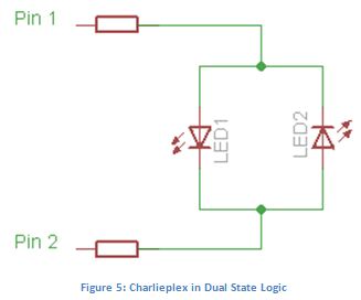
In Figure 5, each pin has two used states: output high and output low. And so, to turn on either of the LEDs, one of the pins must be set to output high and the other to output low. Because the LEDs will not turn on in reverse bias, only one of the LEDs will turn on. In order to turn off both LEDs, both pins could be set to output high or output low. For simplicity, we decide to set both pins to output low to turn off both LEDs. There is a three pin to six LEDs configuration that we initially wanted to use but because a heart rate could be faster than a reasonably quick propagation across six LEDs, we ended up using the two pin to two LEDs arrangement.
Analog Timer
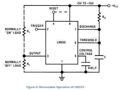
For the analog timer, we decide to use the LM555 because of the availability and overall simplicity of the component. Using a monostable configuration and half shot, as shown in Figure 6 and Figure 7, we were able to drive multiple analog timers with a single pin. The half shot is placed between the output of one timer and the trigger of the next, and so all that was needed to drive an entire string of timers and half shots is a single pin connected to the trigger of the first timer. To avoid any resetting of the timer, we set the Reset pin to VCC.
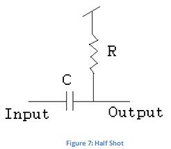
The half shot is designed to charge when the timer output goes high, and then discharge, of course, when the output of a timer goes low. When the half shot discharges, it acts like a negative edge trigger for the next timer(LM555s are triggered with the negative edge). The discharge of the half shot is determined by the RC time constant of the resistor and capacitor.
For this project, we did not really have to compromise much between hardware and software. We swapped in different parts in a few places, such as the IR emitter and receiver, that we will explain later in this document but those were for aesthetic purposes. We also did not see a need upgrade components, such as the LM555, not only because the part worked well but also because the immediate availability of the part in the digital lab. Fortunately enough, we did not have to conform at any standards. Basically, our goal was build a heart rate monitor and have LEDs toggle on and off in response.
Hardware Design
For this project, we use a single ATMega644 soldered onto a prototype board provided to us by Professor Bruce Land. The output of the plethysmograph is hooked up to the MCU´s built-in analog to digital converter. The LEDs can be simply connected to any of the available pins.
We built the plethysmograph using the recommended parts from Figure 3 on a solder board. However, instead of the LTE4208 IR emitter and the LTR4206 IR receiver used in the original schematic, we use surface mount emitters and receivers because they are significantly smaller.
We had tried placing the smaller IR emitter and receiver on the ear lobe so that whoever wears the shirt would have their hands free, but it turned out to be trickier than we thought. Any methods we could come up with, aside from simply holding the sensors with your hands, applied too much pressure on the ear lobe, and pushed out all the blood from the sensor detection area. Ultimately, we had to compromise by putting the sensors on a finger tip.
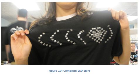
We use LP368PWN1 white LEDs from Newark for the simple reason that they look nicer than the one already in the lab, and fortunately, we use a donated black tee-shirt from Vivian´s brother so that the LEDs would be more noticeable. Because the LEDs are through hole, we simply stick them into the shirt in the shape of a heart and waves as shown in Figure 10.
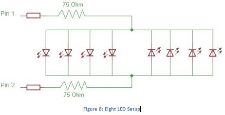
In order to use fewer pins, we connect four LEDs in parallel with each other such that they would be oriented in the same direction between two pins. As a result, there would be a total of eight LEDs between any two pins as shown in Figure 8. To prevent the chance of blowing any of the MCU pins, we connect a 75 Ohm resistor on each pin to limit the amount of current the pins can sink or source.
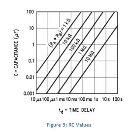
The time delay of the timer´s output in a monostable configuration that can be adjusted according to the nomograph in Figure 9. Because a heart beat ought not to occur every 100ms, we chose a RA of 1M Ohms and a C value of .1µF from the circuit shown in Figure 6. For the half shot, we chose a resistor value of 1M Ohms and .022µF which yielded a time constant of 22ms. Since the time delay of the output of the timer is a little under 100ms, the capacitor would be essentially fully charged every time the timer triggers, and consequently be ready to discharge when it has to.
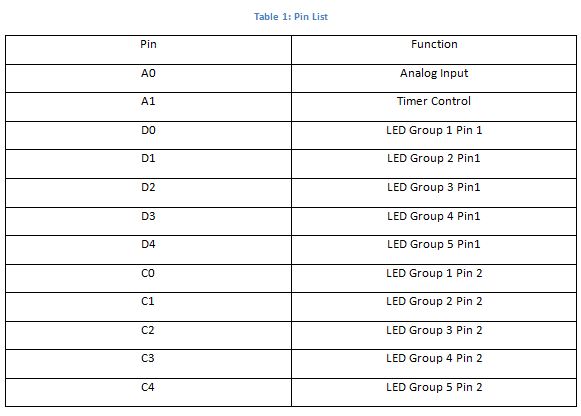
The pin assignments are shown in the Table 1:
Software Design
Our software can be broken into three sections: the timer and interrupt, heart pulse monitor, and the LED control.
Timer and Interrupts
Fortunately, the timer and interrupt code is very simple. We only use Timer0 prescaled by 64 and the compare on match ISR. With OCR0A at 249, the ISR would trigger every 1ms. The ISR task would then decrement two simple time variables that control the two other tasks. Having the ISR trigger every 1ms is fast enough for the comparatively slow heart beat but slow enough for the response time of the LEDs.
Heart Pulse Monitor
Called pulse() in the code, this utilizes the built ADC of the ATMega644 on pin A0. Using the value from the ADC, we are able to determine whether a heart pulse occurs or not. We based this code on lunar lander lab. Because a normal heart rate is around 72 beats per minute, 1 beat every .833 seconds, we chose a sampling rate of roughly 20ms. We felt this was quick enough to get reasonably good precision compared to the relatively slow heart rate, but not too time intensive as to occupy the MCU from performing other task.
In order to help prevent false "heart beats" due to interference on the line, we use a running average of the past 250 values taken in from the ADC. Combining this with a simple two state state machine, we would count any increase of the ADC values as a heart beat only if the ADC values were below the running average first, and we would prepare for the next heart beat after the ADC value drops below the running average. Each time the code would determine an actual heart beat, this would set the trigger for the LED state machine that will be explained in the consecutive section.
LED Control
Called blink(), this task controls the LEDs with a four-state state machine. By setting all the connected pins as outputs and using ten pins in a two pin charlieplex scheme, we control the 40 LEDs. We then use a single pin to control the analog timer. We go through the state machine by simply toggling between output high and output low. The LED state machine will check whether it has to move into the next state every 75ms.
Overall, the code was fairly simple to write. The most difficult code to come up with was the running average. Before the running average, the MCU would consider all rising edges as a heart beat which included any and all interference on the line. Looking into possible solutions, we came up with using an automatic gain control circuit with specific thresholds or a running average scheme. We eventually decided to use running average instead of the AGC because the running average was only code based, and it worked.
Results
The shirt properly propagates whenever the heart beat is detected. There are some false "heart beats" detected as actually heart beats, but for the most part, it works. The LEDs light up when we want and the analog timers react to each other as intended. Also, at first we tried to measure our heart rate via our earlobe, but because of difficulties associated with clipping the detector on the earlobe, we settled on holding it down between a finger. The picture of the final shirt is shown in Figure 10.
Fortunately, we did not have to do much to make our design safe. Although we had many wire connections, we cut the wires to shorter lengths, and covered wire connects with electrical tape not only to prevent the wires from scratching the wearer but also to help electrically isolate the wire from each other. We put the MCU, plethysmograph, and analog timers in inner pockets on the shirt for the same reasons. Our project did not and probably would not interfere with any other project. On the other hand, with the long wire leads in the shirt, our project is more susceptible to any kind of interference, electrical or mechanical. Considering that every now and then we get " false beats ", we can assume they are because of interference.
For the most part, our plethysmograph ought to work with anybody, and consequently, the LEDs. There are only two limitations: the size of the shirt itself and the power cord. The shirt is medium sized so individuals who where shirts larger than that will not be able to wear it comfortably. Because the MCU is being powered by a 12V AC adapter, a wearer cannot really stray too far from the outlet he or she is plugged into.
Challenges
At first, we had trouble detecting the heart pulse from the finger and earlobe. Luckily, we soon found out that loosely holding the IR emitter and phototransistor between the finger did the trick. Unfortunately, we found out that holding the sensor against the ear too firmly would push all the blood out of the area rendering the plethysmograph ineffective.
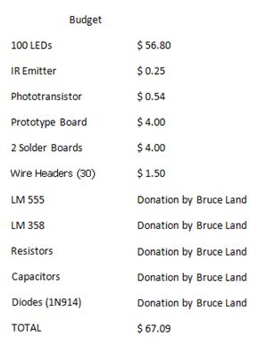
We actually had much trouble deciding on a design for the shirt. The $75 budget limited the number of LEDs we could buy, and we had to compromise the design to do what we envisioned with fewer LEDs.
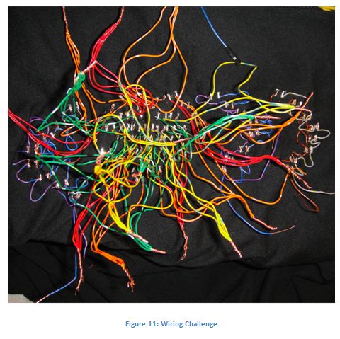
The next biggest obstacle we encountered was the wiring of the shirt. Keeping track of the wires, and making sure there were good connections was not a trivial task. Figure 11 shows the basic wiring mess we had to deal with.
Conclusion
In the end, we successfully designed and created an LED T-Shirt capable of taking the heart rate of the wearer and display it. The product turned out to be more robust than we expected as the plethysmograph was able to take the pulse while the wearer was moving around and talking. To improve further, we could replace all the wires with conductive thread. This would beautify our T-Shirt significantly and make the wiring less of a nightmare.
The code for implementing the ADC function and ISR of the microcontroller was largely adopted from the templates provided to us by Professor Bruce Land for our Lab Practicals of ECE 4760.
For this project, we did not use code in the public domain. We have, however, adopted code from Professor Bruce Land. We also did not reverse-engineer a design. We were inspired by the LED T-Shirt produced by Erogear. We did not receive any sample parts for this project. At this time, we are not aware of any patent or publishing opportunities.
This project had no engineering standards that were applicable.
Our Heart Display LED T-Shirt follows the IEEE Code of Ethics.
Our project does not harm any individual or jeopardizes the community.
If a problem arises, we will be prompt in notifying anyone who might be affected.
We have been absolutely realistic and truthful in our claims in estimates in our data.
We have and will continue to reject bribery in all its forms.
Our project may have improved the understanding of technology and realized the possibility of wearable electronics.
We will continue to improve our technical competence and apply our knowledge only if deemed qualified.
With the knowledge that we acquire, we will assist colleagues and co-workers in their professional development and
support them in following this code of ethics.
If criticism regarding our project arises, we will handle it with professionalism and acknowledge our errors.
We have and will always treat every individual equally regardless of race, religion, gender, disability, age or national origin.
Appendix
Budget
Task Distribution
Vivian Jang: Construction of Plethysmograph and T-shirt, Website,
Nick Lee: Software, Testing of Charlieplex and Analog Timer, Construction of Prototype Board
Code
#include <inttypes.h>
#include <avr/io.h>
#include <avr/interrupt.h>
#include <stdio.h>
#define bt 75 //75ms
#define pt 20 //20ms
#define HEART 0
#define RING 1
#define WAVE 2
#define WAIT 3
#define High 1
#define Low 0
void blink(void);
void pulse(void);
void initialize(void);
volatile unsigned char blinktime, pulsetime; //task timers
char Ain, Ain_prev ; //raw A to D number
//moving avg
char avgarray[250]; //using the past 250 values
char avgpointer, avg; // avgpointer is for navigating the array
int sumavg; //sum of past 250 Ain
char PulseState; //state for pulse
unsigned char count; //state for blink
int main(void){
initialize();
while(1){
if (blinktime==0) {blinktime=bt; blink(); }
if (pulsetime==0) {pulsetime=pt; pulse(); }
}
}
void pulse(void) {
//get the sample
Ain = ADCH;
//start another conversion
ADCSRA |= (1<<ADSC) ;
//results to hyperterm
avgarray[avgpointer]=Ain;
avgpointer++;
sumavg=sumavg+Ain;
if (avgpointer==250){ //full array
avgpointer=0; //reset pointer
sumavg=sumavg-avgarray[0]; //subtract the oldest Ain from sumavg
}
else
sumavg=sumavg-avgarray[avgpointer+1]; //subtract the oldest Ain from sumavg
avg=(char)(sumavg/250);
switch (PulseState){
case Low:
if (Ain>avg) { //rising edge of heart beat
PulseState=High;
count=0; //resets the LED state machine
}
break;
case High:
if (Ain<avg) PulseState=Low; //falling edge
break;
}
}
void blink(void) {
//we use 5 ports from D and C to control the LEDs
//Although LEDs are split into different groups, we just change the controlling
//pins at the same time.
switch (count){
case HEART:
PORTD=(1<<PORTD0)|(1<<PORTD1)|(1<<PORTD2)|(1<<PORTD3)|(1<<PORTD4);
PORTC=(0<<PORTC0)|(0<<PORTC1)|(0<<PORTC2)|(0<<PORTC3)|(0<<PORTC4);
break;
case RING:
PORTD=(0<<PORTD0)|(0<<PORTD1)|(0<<PORTD2)|(0<<PORTD3)|(0<<PORTD4);
PORTC=(1<<PORTC0)|(1<<PORTC1)|(1<<PORTC2)|(1<<PORTC3)|(1<<PORTC4);
break;
case WAVE: //start analog timers with A1
PORTD=(0<<PORTD0)|(0<<PORTD1)|(0<<PORTD2)|(0<<PORTD3)|(0<<PORTD4);
PORTC=(0<<PORTC0)|(0<<PORTC1)|(0<<PORTC2)|(0<<PORTC3)|(0<<PORTC4);
PORTA=(0<<PORTA1);
break;
case WAIT:
PORTD=(0<<PORTD0)|(0<<PORTD1)|(0<<PORTD2)|(0<<PORTD3)|(0<<PORTD4);
PORTC=(0<<PORTC0)|(0<<PORTC1)|(0<<PORTC2)|(0<<PORTC3)|(0<<PORTC4);
PORTA=(1<<PORTA1);
break;
}
if (count>=WAIT)
count=WAIT;
else
count++;
}
void initialize(void){
DDRA=0xfe; //all outputs except for A0
DDRD=0xff;
DDRC=0xff;
//set up timer 0 for 1 mSec ticks
TIMSK0 = 2; //turn on timer 0 cmp match ISR
OCR0A = 249; //set the compare reg to 250 time ticks
TCCR0A = 0b00000010; // turn on clear-on-match
TCCR0B = 0b00000011; // clock prescalar to 64
//init the A to D converter
//channel zero/ left adj /EXTERNAL Aref
//sets prototype board's Aref
ADMUX = (1 << REFS1) | (1 << REFS0) | (1<<ADLAR);
//enable ADC and set prescaler to 1/128*16MHz=125,000
//and clear interupt enable
//and start a conversion
ADCSRA = (1<<ADEN) | (1<<ADSC) + 7 ;
Ain_prev=0;
blinktime=bt;
pulsetime=pt;
count=WAIT;
PulseState=Low;
avgpointer=0;
sumavg=0;
avg=0;
sei();
}
ISR (TIMER0_COMPA_vect){
//Decrement the task timers if they are not already zero
if (blinktime>0) --blinktime;
if (pulsetime>0) --pulsetime;
}
Reference
Mega644 Datasheet
http://courses.cit.cornell.edu/ee476/AtmelStuff/mega644full.pdf
Wikipedia-Charlieplexing
http://en.wikipedia.org/wiki/Charlieplexing
IR Emitter
http://www.vishay.com/docs/81300/81300.pdf
Phototransistor
http://www.us.kingbright.com/images/catalog/SPEC/APA3010P3BT.pdf
LEDs
http://www.cree.com/products/pdf/LEDlamps/LP368PWN1-D0G%28123%29.pdf
LM555 analog timer
www.national.com/ds/LM/LM555.pdf
Erogear
http://www.erogear.com/index.html
Professor Bruce Land
Vendors and Parts
Newark LEDs Part No: 02P7177Newark IR Emitters Part No: 31M2974
Digikey Phototransistors Part No: 754-1067-1-ND
Lab: LM358, LM555
Acknowledgements
Nick and I would like to thank Professor Bruce Land for helping us making the LED T-Shirt a reality.
We'd also like to thank all our TAs for helping us out.