 Yunchi Luo yl477Mengliang Yu my288
Introduction
We created an image scanner that uses a phototransistor array to detect light intensity and then transmits all data to MATLAB for processing.
Normally, image scan is done with a CCD overlaid with a photoactive layer of silicon. When light strikes the sensor array, the CCD shifts charge through stages of capacitors into a charge amplifier, which in turn converts the charge to a voltage signal. Repeating this process creates a digitizable signal that the scanner stores into memory to create an image.
Our goal for this project was to explore the concept of using an array of phototransistors to replace the function of the photoactive silicon layer. We built an array of phototransistors and attached them to an X-Y plotter so that they could scan a large area. Light signal detected by phototransistors is captured by the Mega644 A/D converter and then transmitted to MATLAB using a serial connection. MATLAB scripts were created to control the scanner as well as perform image process.
High Level Design
Rationale
We wanted to build a camera that would be able to capture still-images using phototransistors or photodiodes. The idea was that we would align 8 phototransistors in a row (one for each of Mega644's analog-to-digital converter port), and scan row by row in a rectangular area to capture an image of whatever was in front of it. It was to be the realization of the concept that a fairly viewable image can be constructed by piecing together light intensity information in each scanned area. It's clear that the image would be very low resolution, but should still be recognizable to some extent.
The inspiration for using an X-Y plotter to control the movement of the phototransistors came from Bruce Land and a project called "Scanner" designed by Andrew Hocker and Bor-Hann Fang. Their scanner was built using an X-Y plotter and a single Phototransistor reflective object sensor (QRB114) . We decided that this served as a good basis for our project. Some significant modifications needed to be made since what we are making is meant to be closer to a camera than a scanner. The X-Y plotter that Andrew and Bor-Hann built functions as a flatbed scanner and scans only paper placed on the X-Y plotter platform. The scanning process was also very slow because there was only one sensor, and low resolution. We wanted to build a scanner that can scan in any orientation, at reasonably distant targets. The scanning process needs to be also relatively fast because among the subjects we hoped to capture were human faces, which usually don't enjoy remaining still for long periods of time.
Finally, in an attempt to improve image quality and resolution, we decided that we needed to interface with MATLAB and transmit all data into MATLAB to perform image process. Given the fact that MATLAB has numerous built-in image processing functions, we would be able to enlarge our initial image as well as increase its resolution.
Background Math and Physics
The photoactive device we used in our project is the phototransistor. When light reaches a phototransistor, the electrons that are generated by photons in the base-collector junction are injected into the base. This current is amplified by the transistor's current gain. With our choice of phototransistor, the current caused by the incident light is nearly a linear funciton of the light intensity. We used phototransistors as emitter followers, as shown in Figure.1.
Figure.1 Phototransistor Emitter Follower
Vout is determined by the current flowing through resistor Re so we have Vout = I*Re. Based on the characteristics of the phototransistor, the current I is proportional to the intensity of the light strikes on the phototransistor, so we can describe the output voltage as a function of light intensity that Vout = I(light intensity)*Re, where Vout is also proportional to the intensity of the light that strikes on the phototransistor.
For our scanner, the light reaches the phototransistor is reflected from the image it is scanning. A light color such as white or yellow will result in a higher Vout value because it can reflect more light into the phototransistor comparing to a dark color such as blue and black. All Vout values that generated by phototransistors will be captured using Mega644 A/D converter and then transmit to MATLAB interface, where the image will be processed and restored.
Logic Structure
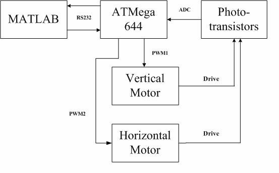
Figure.2 High-level Logic Structure
The high-level design of our project is shown in Figure.2. It shows the flow of data, from when the scanner is first started with MATLAB command to when ATMega644 sends all data captured by A/D converter back to MATLAB.
The scanner is started by calling a function in MATLAB interface and then the command is transmitted to ATMega644 by serial connection. Three stepper motors, two horizontal motors and one vertical motor, are used to drive the X-Y plotter. ATMega644 will control the movements of all three motors, which are powered by ULN2003 Darlington arrays. Our phototransistor array is consisted of eight PS5022 phototransistors. The scan steps through row-wise, from left to right until the end of the range of movement, shift the rail down, and then sweep leftwards, repeating until the entire area has been swept. For each scan step, A/D converter will capture all Vout values generated by the phototransistor array and then ATMega644 will send the data back to MATLAB. All data will be stored in a matrix in MATLAB during the scan.
Once the scan is finished, the phototransistor array will be reset to the initial location. At the same time, MATLAB will convert the data stored in the matrix into a bitmap picture and display it. We also wrote some MATLAB functions for further image processing which will help us to get pictures with higher quality and resolution.
Hardware/Software tradeoffs
One of our major limitations was the budget as it forced us to choose a photoactive device which was not our optimal choice. Our final design of the phototransistor array consisted of eight PS5022 phototransistors. But if there were not a restriction on our budget, we could have used integrated photodiode array instead (such as HAMAMATSU S8558 Si PIN photodiode array), which is more accurate and sensitive. It could provide us with much better light signal. Though the integrated photodiode array has an excellent performance on detecting light signal, it is very expensive and way out of budget (HAMAMATSU S8558 is $27 each). We had to abandon the idea of using it.
Another important limitation came from the fact that we had to fix the entire phototransistor array and its corresponding circuit on the head of our x-y plotter. This limited the number of phototransistors we could use as well as the complexity of the circuit we could implement. We could have achieved higher scan speed if we would be able to use more phototransistors for our phototransistor array. In addition, we could even build a light-intensity-adjustable scanner using potentiometers. This will be further discussed in Future Improvements part below.
There were some other limitations as well. For example, we used MATLAB built-in function to deconvolve the data we got in order to improve the image quality. But deconvolution calculation is time-consuming task, as 50 iterations in MATLAB could cost several minutes. So we ended with using only 20 iterations. Though the image quality is not as good as doing deconvolution for 50 iterations, it is acceptable.
Relevant Standards and Copyrights
RS232
RS232 (Recommended Standard 232) is a standard for serial binary single-ended data and control signals connecting between a DTE (Data Terminal Equipment) and a DCE (Data Circuit-terminating Equipment) in telecommunication. It is commonly used in computer serial ports. We used the RS232 communication standard for transmitting phototransistor measurements directly to MATLAB on the PC. Our RS232 interface on the MCU side is actually handled by the MAX233 chip, so we fortunately did not have to deal with the details of implementing the RS232 functionality and just used the USART interface.
Bitmap
After scanning the image and transmitting to MATLAB, the processed image is stored using the Bitmap file format (jpg). Our bitmaps are actually generated directly by MATLAB, and are stored using 8-bit color depth (grayscale). The jpg files created can be opened by any software program that is able to open the standard bitmap format.
Improve Image Resolution
In post-processing the captured images, we used a script created by Francisco de Castro, made available under the BSD license. The script uses a popular method of interpolation called Piecewise Cubic Hermite Interpolating Polynomial (PCHIP) to increase the resolution of the image while retaining image detail.
Design
Our hardware design did not use any patented components. Our phototransistor gain circuit is a commonly used photocell circuit and is not patented.
Implementation Details
Mechanical Design
The mechanical design was perhaps the most difficult part of our project, partially because we are ECE students who have much more experience with theory than building things with our hands. We changed our design several times during the actual machining because it was either too difficult to build or would make us go over budget.
As discussed in the high level design, we decided to mount our phototransistor array to the head of an X-Y plotter. However, X-Y plotters are meant to draw on a piece of paper, so some redesign was needed to make it so that our X-Y plotter can function in any orientation, while still stay under budget. While a vertical plotter has previously been built in this class, it was not accurate enough, and can only function vertically, not horizontally.
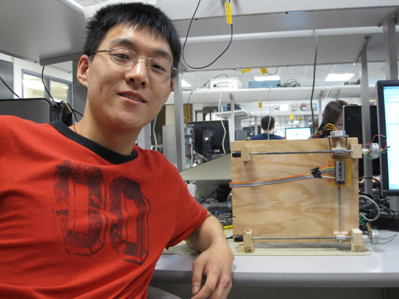
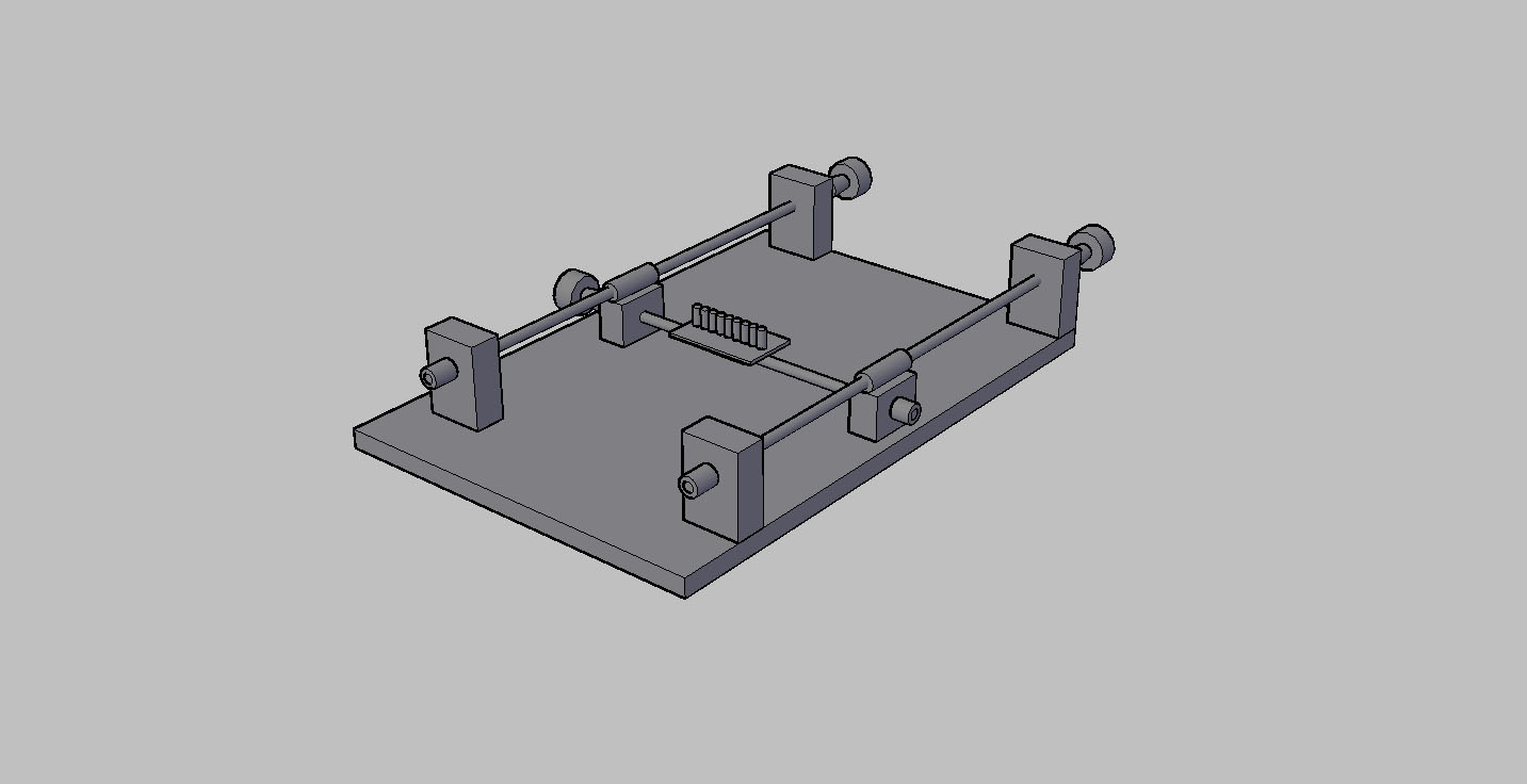
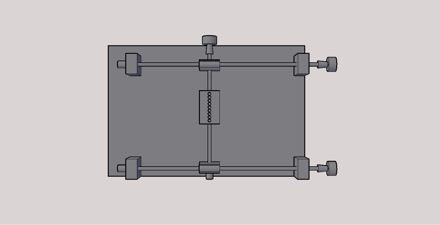
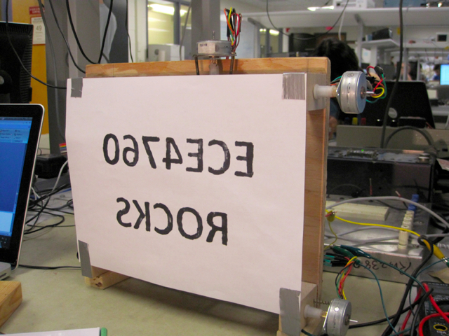
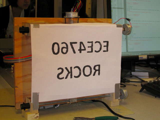
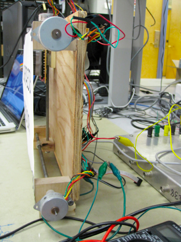
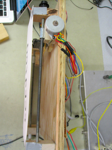
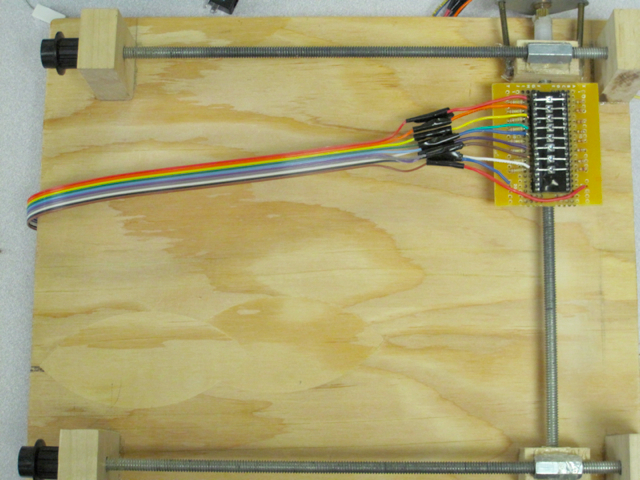
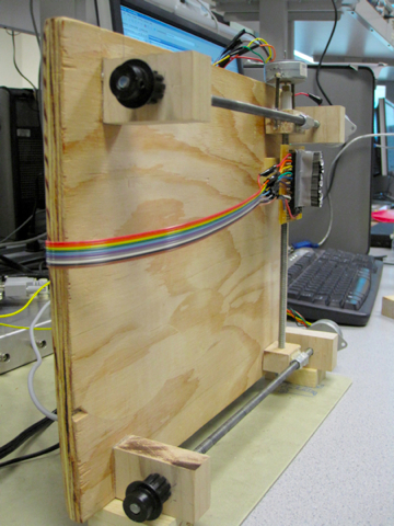
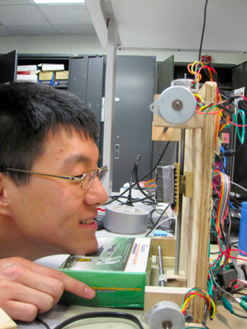
Our final design was based on a much more rigid implementation, a fischertechnik plotter by Procon Technology. While the plotter definitely satisfied our functional requirements, a quick Google search determined that the price tag for the parts totaled over $100, far more than the budget of $75 we had to work with. After a few design iterations, we were able to replace the fischertechnik parts with building tools that could be purchased at the local Lowe's. Below is a picture of our finished model.
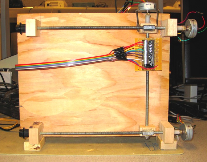
Figure.4 Picture of finished plotter.
In our design, we used the concept of a screw drive. Usually, nuts turned along a threaded rod, typically a bolt, to tighten something in between. Instead of turning the nut, we keep its orientation with respect to the wooden platform fixed, and turn the rod. This causes the nut to move along the rod as the rod is turned. The movement is extremely accurate because the threading tend to be very dense. In our case, the rod had 20 turns per inch of threading, which translates into 0.026458mm of movement per stepper motor step (7.5° turn).
In the assembly, we have 2 parallel metal threaded rods mounted onto a wooden platform using wooden blocks with holes drilled into them. The two threaded rods have another perpendicular vertical threaded rod mounted onto the nuts that are on each rod. Then, a PCB board with the phototransistor array is mounted onto the nut that is threaded onto the vertical rod. The horizontal rods allow the horizontal movement of the vertical rod, while the vertical rod allows the vertical movement of the plotter head (the phototransistor array in our case).
To keep the nuts from freely spinning when the rods turn, we used small wooden blocks that were just wide enough to fill the space between the nuts and the wooden platform, gluing them onto the nuts. The wooden blocks keep the nuts from turning. The wooden blocks fixated onto the horizontal rods also have holes drilled into them to thread the vertical rod through. We had to find hardwood, some oak that Paul at the Hollister machine shop was kind enough to provide us with, so that the threads did not grab onto the wood and create unneeded friction as they turned. For the vertical rod, we actually ran into some friction problems between the wooden block glued on its nut and the wooden platform. We had to sand down both the block and the platform quite a bit to allow free movement.
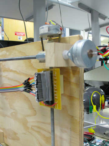
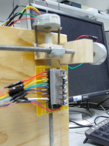
The rods were turned using stepper motors. To connect the rods to the stepper motors, we used some chair leg caps that had threaded plastic tubes, found in the ECE lab. We put our threaded rod in one end and glued our motor's gear in the other end, creating a relatively strong and flexible but very reliable connector for the stepper motor. Furthermore, we needed a way to fix the stepper motors so that they turn the threaded rods instead of turning freely themselves. Luckily, the stepper motors had screw holes, so we inserted screws and fixed them onto the wooden blocks that the threaded rods we put through. However, we couldn't tighten the screws too much or it would cause too much friction for the motor, but looser screws gave the motors some freedom to move and created a lot of noise. A little hot glue fixed both problems.
Another important issue in our mechanical design was the synchronization of the 2 horizontal rods. The nuts on each rod need to be at the same position vertically at any time, or our scan would get distorted, and it would also be very difficult for the vertical motor to turn due to increased friction. In the final design, we used 2 stepper motors whose inputs are driven by the same ports of the MCU, powered through separate ULN2003s. This design gave us the largest amount of torque, since there were 2 motors. However, the use of separate motors to drive each rod required that we calibrate the nuts on the 2 horizontal rods carefully every time they go out of sync or neither motor can spin at all. In addition, each motor uses about 0.5A, so an additional motor increased our power usage significantly. This is a major tradeoff we had to make, as described later in the previous attempts section. Our original intention was to use a timing belt to synchronize the two horizontal rods.
Electrical Design
Our hardware design mainly consists of three parts: the Custom PCB for ATMega644 and Max233, phototransistor array circuit and ULN2003 circuit. All hardware schematics can be found in Appendix B: Hardware Schematics.
ECE 4760 Custom PCB
We used the ECE 4760 Custom PCB (printed circuit board) to interface the ATMega644 MCU with our external circuits. This Custom PCB board is designed by ECE 4760 instructor Bruce Land. The actual printed design is shown in Figure.5.and the our board layout is shown in Figure.6.
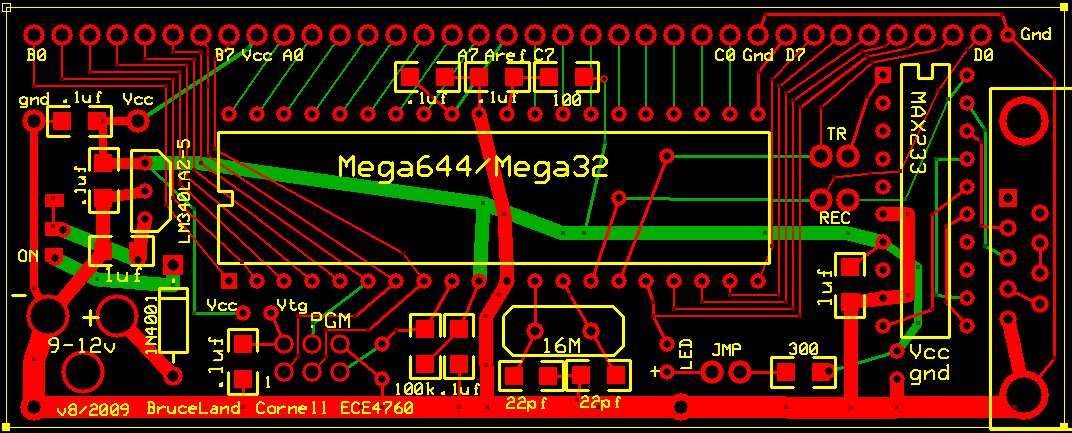
Figure.5 ECE 4760 Custom PCB

Figure.6 Board Layout
This board is powered by an external 9-12V power supply. A National Semiconductor LM340LAZ-5.0 regulator is used to convert the 12V power supply to 5V Vcc. To avoid destroying the regulator by applying negative voltage, a 1N4001 diode is put between the positive power input and the switch. A 32-pin socket is required for placing ATMega644. The stem clock will be generated by CTX077 16MHz crystal. To program the MCU, a six-pin programming port (PGM) is also needed. Our project uses serial connection so we added a 9-pin RS232 connector and another socket for the MAX233 level shifter. We also added one LED and jumper for debugging. Toggling PortD.2 will flash the LED to let us know that the MCU is running. After all components were soldered, we tested our Custom PCB using this C program to make sure we got everything right.
Phototransistor Array Circuit
We used Stanley PS5022 Phototransistor as our photoactive device. The data sheet for PS5022 is available here. There were several reasons why we chose PS5022: it is cheaper than other similar products and it could provide us with relatively high visible light sensitivity. Its spectral characteristics peaks at around 880nm and it could respond to wavelength less than 500nm, which is good enough for our project.As discussed before, we used the phototransistor as emitter-follower which has Vout = I*Re . We used eight phototransistors in a row our phototransistor array. The schematics are shown in Figure.7.
Figure.7 Phototransistor Array
Rc and Re values were determined experimentally. We tested the circuit under several different lighting conditions. After experimenting, we found that our circuit had the most sensitivity with Rc = 20kΩ and Re = 180kΩ. At the same time, Vout does not exceed the reference voltage of 2.56V that we use for the ADC when under natural light conditions. We measured all the resistors we used in the phototransistor array to make sure all deviations from the design value range within ±5%. The measurement results are shown in Table.1
| Resistor | R1 | R2 | R3 | R4 | R5 | R6 | R7 | R8 | R9 | R10 | R11 | R12 | R13 | R14 | R15 | R16 |
|---|---|---|---|---|---|---|---|---|---|---|---|---|---|---|---|---|
| Design Value (kΩ) | 20.0 | 20.0 | 20.0 | 20.0 | 20.0 | 20.0 | 20.0 | 20.0 | 180 | 180 | 180 | 180 | 180 | 180 | 180 | 180 |
| Real Value (kΩ) | 19.9 | 19.9 | 20.0 | 19.9 | 20.0 | 19.8 | 19.8 | 19.9 | 176 | 178 | 179 | 178 | 180 | 179 | 176 | 178 |
Table.1 Resistor Measurement Results
Actually, PS5022 phototransistor has a spatial distribution of around ±15°. To get an image with higher resolution and better quality, we made some carefully hand-rolled collimators which could narrow the spatial distribution as much as possible, as shown in Figure.8. These collimators were made from paper and electric tape and they worked well in our project. Without them, we could not have achieved a reasonable image resolution.

Figure.8 Phototransistor Array with Hand-Rolled Collimators
To capture light signal generated by the phototransistor array, we connected all eight Vout pins to ATMega644's A/D converter, which is from PortA0 to PortA7, as shown in Figure.8. The entire circuit is powered by 5V voltage supply generated by the regulator on the Custom PCB. After we soldered the entire phototransistor array circuit, we tested this circuit by connecting each Vout pin to the oscilloscope. We checked the waveforms under different light conditions to make sure the variations of the output voltage were big enough as we designed to be.
ULN2003 Circuit
The ULN2003 chip is used to drive our stepper motors. It is high-voltage high-current Darlington transistor arrays. Each of the ULN2003 consists of seven NPN Darlington pairs that feature high-voltage outputs with common-cathode clamp diodes for switching inductive loads. Every single Darlington pair has a collector-current rating of 500mA. The ULN2003 chip is our best choice to drive our stepper motors. Its data sheet can be found here. Stepper motors are used to drive the X-Y Plotter in our project. A stepper motor is a electric motor that is able to divide a full rotation into a large number of steps. The stepper motor we used in this project is NIPPON PF35T-48L4, which was provided by instructor Bruce Land. As described in the data sheet , this is a unipolar 6-wire center tap motor, meaning that the two center wires in each three wire set are common (12V), while the other 4 wires are held to ground at separate times to turn the stepper motor
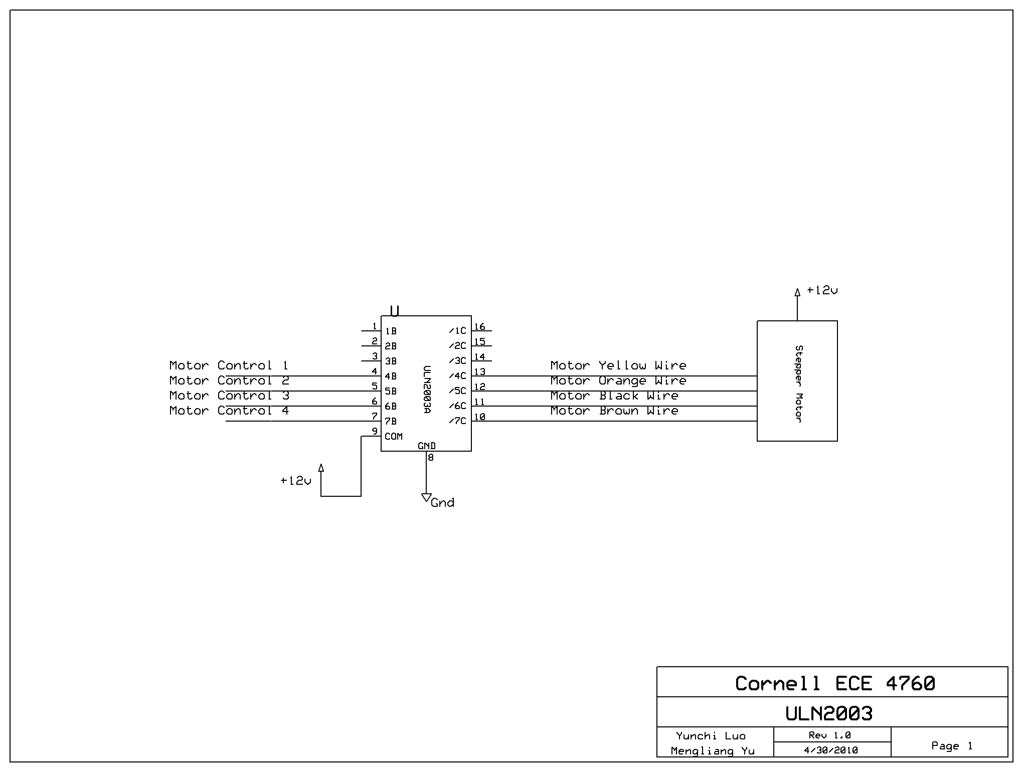
Figure.9 ULN2003 motor-driving circuit.
The UNL2003 chip is placed in a 16-pin socket, which is soldered on a 2-inch small solder board. All three of our stepper motors, one vertical and two horizontal, are drvien by this ULN2003 circuit. This circuit as well as our stepper motor are powered by a +12V LCD power supply, as shown in Figure.9 above. These stepper motors are controlled by the ATMega644 MCU, which will generate waveforms to be fed into the Darlington array chip to drive our stepper motors. More details about waveform generations will be discussed later in Software Design part.
After finished testing each part, we grouped everything together. The full circuit schematic is shown below in Figure.10.

Figure.10 Full Schematic.
Software Design
Motor Control
The motor control code makes up most of the code for the MCU. We have two state machines running simultaneously in the Timer0 Overflow ISR, one for the horizontal motors and the other for the vertical motor. The prescalar is set to 8, and an additional software counter variable (pulse_width) is used to get finer control over the stepper motor's control pulse width. The pulse needs to be wide enough that the stepper motors get enough torque to turn the rods, but not so wide that they become too slow. The minimum value was determined experimentally to be 34. The RPM of the motor is determined using the formula (16MHz*(60s/min))/((prescalar)(255) (pulse_width) (360°/ (7.5°/step))).
As explained in the electrical design, we use unipolar 6-wire center tap stepper motors for this project. Four of the wires are held to ground at different times using square wave pulses to make the stepper motor turn. From the MCU side, a high pulse is sent to the selected output, which causes the ULN2003 to drive the corresponding input of the motor to ground. The outputs for the horizontal motors are PORTB0 thru PORTB3. The outputs for the vertical motor are PORTB4 thru PORTB7. For the horizontal motors, asserting pins B0, B2, B1, B3 in that sequence causes the motors to turn clockwise, while the reverse order causes them to turn counterclockwise. The procedure for the vertical motors are similar.
Two position variables are used keeps track of the X and Y positions of the motor. To move the motor, we set the desired X and Y positions. The horizontal (X) and vertical (Y) state machines in the ISR will then run continuously until the value of the actual position match the desired position. We wrote the state machines separately so that the scanner head can move in both the X and Y directions at the same time for faster adjustments. We also write macros for converting from millimeters to the number of steps the stepper motor needs to turn. There is also a function for setting the desired position of the motor while checking bounds. We implemented the motor movement this way so that issuing the move command returns immediately instead of blocking until the desired position is reached.
The state machines used for the both sets of stepper motors are simply counters with a maximum value of 4, where each state corresponds to asserting one of the 4 outputs to the stepper motor. After the fourth state, the counter returns to 0. Each time the ISR runs, the state and X or Y position is either incremented or decremented, depending on the direction of movement. The state machines will continue to run until the desired position is reached, after which they just continue to hold the previous state, so that the stepper motors hold the scanner head's position.
Finally, for the scan, the motor moves at incremental steps across horizontally, then moves down, and sweeps back horizontally. This repeats until the entire area is scanned. These steps are not the stepper motor steps but step sizes of 5 millimeters, which is the diameter of our collimator. The movement down at the left and right edges are 40 millimeters, because the 8 phototransistors are arranged vertically adjacent to each other.
The frequency of the ISR has no effect on the functionality of the plotter, except that if the stepper motors run too fast, they are unable to provide enough torque to turn the threaded rods. The prescalar is set to a nominal value of 8. We find that the stepper motor's maximum speed is with a pulse_width of 34, which is calculates to about 288 RPM.
Analog-to-Digital Converter
We used the ADC to obtain voltage measurements from the phototransistors. The reference voltage used is 2.56V, which we selected by experimenting with the voltage measurements at different lighting conditions. Measurements of type of reflected light do not exceed 2.5V unless a bright light is shined too close by. We take 8 of the 10 bits that the ADC reads and use it directly as a grayscale value.
We use all 8 ports available to the ADC (PORTA0 thru PORTA7) on the Mega644 chip to connect the 8 phototransistors. In every scan step, each of input ports are measured in turn by incrementing ADMUX. In every iteration of the scan loop, we stall until the ADSC bit in ADCSRA is set to high, indicating that a conversion is finished so that we do not overwrite any previous values.
Serial Connection
The serial connection is used to transmit the grayscale values obtained by the ADC to MATLAB for image processing. For convenience, we also wrote some code to receive the START and STOP commands from MATLAB. We implemented the serial connection using the provided uart code that controls the MCU's uart interface, and MATLAB's serial interface.
For the receive, we actually used a modified getchar function by instructor Bruce Land that does not echo the input bytes (the default getchar function in the provided uart code echos the input data back to the transmitter). This is done so that in the case an invalid command is sent, the stream of phototransistor measurements being sent from the MCU does not get corrupted with the echoed data. So as to not waste any CPU time on polling for received inputs, we used the USART0 RX ISR which triggers whenever a receive completes. The START command, sent as the string, "start", starts the scan loop. The STOP command, sent as "stop", stops the scan loop immediately and moves the scanner to its starting position.
The code for sending data is much simpler. After every ADC conversion, the upper 8 bits of the conversion, available in ADCH, is sent through the serial interface using the uart_putchar function, since a char is exactly 8 bits. MATLAB reads all of the data as they arrive, as described in the MATLAB section.
MATLAB Image Process
In order to increase the resolution and quality of the initial image we get from the scanner, a MATLAB function called imageProcess (imageProcess(bitmap, threshold1, var1, threshold2, var2)) was written to perform some image-processing techniques.
First, the function imageProcess reads all given parameters and loads the initial bitmap generated by the scanner and displays it. It then increases the image contrast and makes it ready for further processing. The contrast increase is done by calling a sub-function named BW (BW(bitmap,threshold1,var1)). This function reads a threshold value(threshold1) and a variation(var1) value from the parameters. Grayscale values in the bitmap matrix that are smaller than the threshold value(threshold1) will be reduced by (var1+20) while gray scale values that are bigger than the threshold value(threshold1) will be set to 255. By performing these calculations, the function BW was be able to increase the contrast and eliminate noises.
To enlarge the initial image, a function named iir is used. This function was created by Francisco de Castro, as mentioned above in Relevant Standards and Copyrights part. The function iir uses a popular method of image processing technique called Piecewise Cubic Hermite Interpolating Polynomial (PCHIP) to increase the resolution of the image. In this project, we increase the resolution by 21X.
After the enlargement of the image is finished, the imageProcess script uses MATLAB's built-in function deconvblind() to deconvolve the enlarged image. "Deconvolution" refers to the process of reversing the optical distortion that takes place during our scanning. Our image has optical distortions which come from the fact that PS5022 phototransistor has a spatial distribution of ±15° so the image captured by these phototransistors is overlapped in some area. Though we used collimators to reduce this effect, there would always be some optical distortions. Finally, the deconvolution takes a relatively longer period of time. Once the deconvolution is finished, BW is called again with parameters threshold2 and var2 to further increase the contrast. Then the processed image is displayed. The entire process is shown below.
Figure.11 initial image captured by the scanner

Figure.12 enlarged image
Figure.13 deconvolved image
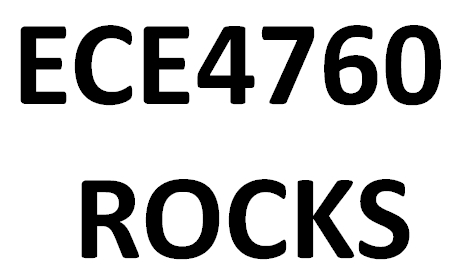
Figure.14 processed image
Previous Attempts
We went through several iterations for the mechanical design, due to our lack of experience in building mechanical devices and monetary constraints. We originally wanted to use worm gears to turn the rod, but it was too difficult to find a matching gear, and worm gears were too expensive to buy. Directly fixing the motor onto the rod wasn't practical because it would be too easy for the motor to break off. Luckily, there was a box of unused chair leg caps with threaded plastic tubes that we could use to terminate the threaded rods and insert the motors.
With regard to the synchronization of the top and bottom horizontal rods, our original intention was to use a timing belt. Timing belts are used in almost all engine systems to synchronize the rates at which each gear or axle is spinning. This would make it practically impossible to get the 2 rods out of sync. However, timing belts need to be kept under a reasonable amount of tension so that the teeth do not skip. After attaching the timing belts onto the rods, they caused too much friction between the rods and the wooden blocks that the rods spin inside. The torque required was higher than a single stepper motor could provide. Eventually we gave up on reducing friction in the wood and used 2 separate stepper motors in sync to drive the 2 horizontal rods. This reduced our budget by quite a bit because the timing belt was expensive, and immediately reduced the friction enough for the rods to turn. However, the addition of a stepper motor increased the power usage by a large amount.
When choosing light sensors to use for the scanner head, we originally wanted to use photodiodes due to their higher sensitivity to dim lighting conditions. However, after performing some experiments using many different kinds of phototransistors and photodiodes, we realized that it was impractical for us to obtain photodiodes that are responsive enough to the visible spectrum. Silicon and GaAs photodiodes and phototransistors are built usually with a peak response in the infrared range and are not nearly as sensitive to visible light. It would be extremely difficult to capture images using these devices. After thorough searching, we found that phototransistors tend to have a larger range of response, though they were not as good under dim lighting. We eventually decided to use the PS5022 phototransistor, which while peaked at infrared, still has good response in the visible spectrum.
Results
Speed
There are no timing issues in our design. The serial connection responds function call without any noticeable latency. The speed of our scanner is determined by the frequency of the ISR controlling the motors. The frequency has no effect on the functionality of the scanner, except that if the stepper motors run too fast, they are unable to provide enough torque to turn the threaded rods.
Through experimentation, we chose a prescalar of 8. We found that the stepper motor's maximum speed is with a pulse_width of 34, which calculates to about 288 RPM, or 36.57cm/s since we used 20 turns/inch threaded rods. The scan area is about 180mm×80mm. It takes the scanner about 100 seconds to scan the entire area. Though it takes a much longer period of time to scan an image compared to commercial scanners, we are satisfied with the speed.
Accuracy
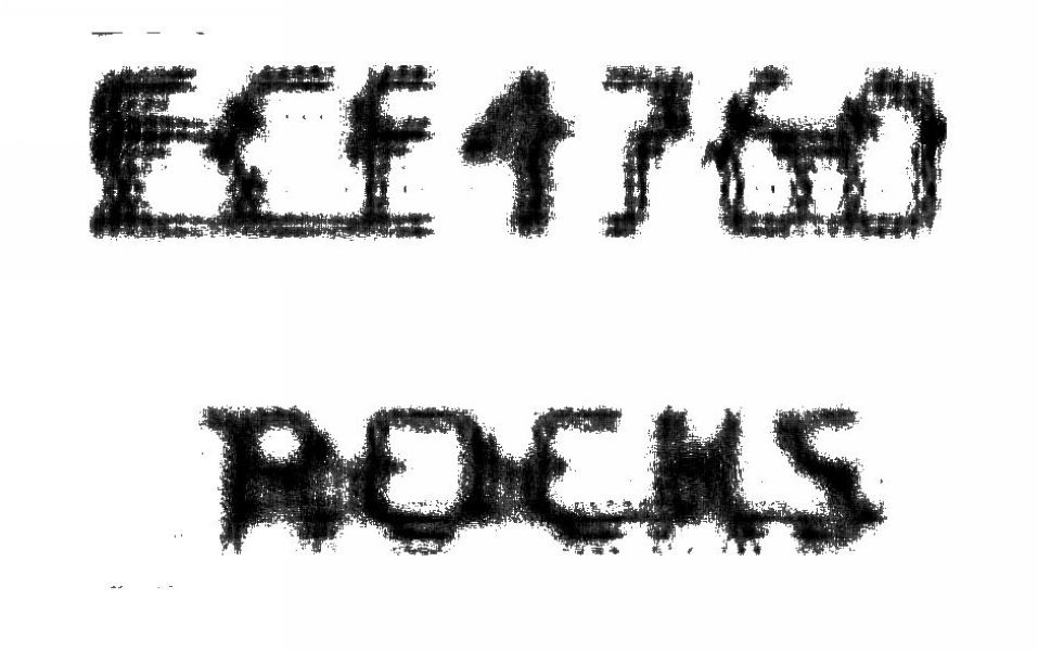
As discussed before, we had to make many tradeoffs for our design. These tradeoffs affected the accuracy of our scanner. The Stanley PS5022 phototransistors worked well if we were scan some simple text. In fact, it could also scan some complicated 3D objects under good light conditions. When we tried to scan Yunchi's face using our scanner, it actually did a fairly reasonable job. In the figure below, you can recognize Yunchi's eyebrows, eyes and noses from the image. Even his glasses are recognizable.
Figure.15 Yunchi's face
However, the captured image would be unrecognizable if we were scanning under dim or very bright conditions, or the distance between the phototransistor array and the object was large. The reduced accuracy results from the fact that PS5022 phototransistor is still not sensitive enough for our purposes. However, we are still very satisfied with our results, since we can actually scan a human face and recognize it from the picture
With respect to the mechanical accuracy of the X-Y plotter, our accuracy is extremely high. Every step of the stepper motor translates to a 0.026458 mm movement along the thread, with 20 turns/inch threads and 7.5° per step turns. All of the motors are fixed to the wooden supports so there is no error due to motors torquing. We can actually further improve accuracy by using half-steps with the stepper motor, but this would double the power consumption and is unnecessary for our application. There is some small error introduced due to that the step motors need to be loose enough that they don't add too much friction.
Safety
There are no electrical and mechanical safety concerns in our project. The highest voltage we were dealing with is +12V power supply, which is still a safe voltage value. It is not high enough to cause a safety risk. While we do have moving parts, the threaded rods turn on an axis and are slow enough to be safe. The scanner head moves within a very clear limited range, and require very little force to stop completely. We adjusted the speed of the stepper motors to the extent that they get just enough torque to turn the rods, but putting a finger on the scanner head will stop the whole thing. All motors are fixed to the supports by wood and hot glue so nothing can move other than the scanner head. The only safety concern is that the motors can get hot enough to burn skin on contact. This is an unavoidable issue because we are using stepper motors, which require current even while holding position
Usability
Our scanner is very easy to use. Once the switch is turned on, all commands can be given through the MATLAB interface. To start the scanner, just call run_scan. If you want to stop the scanner during scanning process, stop the run_scan script and issue fprintf(s,'stop'). It will stop the scanner and reset the head to the initial location. The image process function is called in the same way. After the scanner stops, simply call imageProcess with all parameters required parameters to start the deconvolution and interpolation.
With respect to mobility, it will be somehow difficult to carry or move the scanner. The scanner is a bit heavy and it has two power supplies that need to be connected before using. The size of our scanner can be reduced by integrating all small components together and using only one suitable power supply instead of two. Disabled persons will be able to use our device just as well.
Conclusions
Expectations
Overall, our project exceeded our expectations. We thought that our final mechanical design would be flimsy and required care to set up for use each time. This turns out not to be the case as our scanner could be carried around without easily being damaged, and the only thing that needs to be done every time the scanner is set up is to connect the power and serial connections.
With the close-up scans of printouts, we are very pleased with the results. The resolution is much higher than what we expected to have. Our scanner is a significant improvement over the previous "Scanner" project, having much higher resolution, scanning speed, and the ability to scan in grayscale. Also, our images can actually be held at a relatively long range (several centimeters), and still be able to resolve what was scanned, with or without image processing.
The results with scanning real objects were also very successful. We scanned some well defined shapes like glass bottles, fingers, and a roll of duct tape. Each of these yielded clearly recognizable images. However, the scanning of a human face was somewhat less successful. While a face can easily be seen in the picture that is taken, it is relatively difficult to tell whose face it is. By adjusting the ambient light we were able to achieve much better results, but still not sufficient clarity in the image.
If we had more time we would improve on the resolution of the image. This can be done by scanning in increments smaller than the spacing of the phototransistors. The resulting picture would require much more advanced deconvolution techniques to process, but would most likely also yield much clearer pictures. Another possible significant improvement to the resolution is to install lens within each of the collimators. This would allow light to focus much better on the phototransistors and improve the spatial distribution of light. We chose not to do this for our project because it would be difficult to align the lens correctly and they are rather expensive.
If we had enough space on the head of the X-Y Plotter, we would have built a light-intensity-adjustable scanner using potentiometers and an additional ambient light sensor. This would help us to improve accuracy under very dim/bright light conditions. We could even add more phototransistors, supplementing the ADC's input ports using external multiplexers controlled by another port on the MCU. This would result in faster and higher resolution scans since our speed is limited by the motors.
Conformation to Standards
Our project conforms to the RS232 standard for serial connections. On the MCU side, the communication protocol is handled by the USART and the MAX233CPP, while MATLAB handles the PC side. We did not have to do any low level implementation of the standard. Our use of the bitmap format is also standard. MATLAB saves bitmaps in 8-bit grayscale format, and is readable by any image software that supports the standard bitmap format.
Intellectual Property Considerations
As mentioned before, we used Francisco de Castro's code for improving image resolution. The code is freely available under the BSD License. We also used lightbox on this website written by Lokesh Dhakar, available under the Creative Common Attribution 2.5 License.
The X-Y plotter is a concept that has a few patented implementations. Ours is a unique implementation of the X-Y plotter and does not impinge upon any existing patents, and is itself patentable, though we have no desire to do so. Our design will be freely available to anyone who wants rebuild it and improve upon it.
Ethical Considerations
As technology become more integrated into our everyday lives, the ethical considerations for new products with respect to safety and quality become even more important. Small mistakes or oversights in design have the chance of causing profound changes on the quality of life of individuals, many who are not the direct target of the products. While our scanner does not have any significant effect on the safety, health, or welfare of individualss, we made following the IEEE Code of Ethics during the design of all parts of the scanner.
We made our design decisions with the safety of the user in mind. While building the X-Y plotter, we reduced the number of moving parts to the bare minimum to decrease the chance of the user being harmed. Any moving components also move at low speeds, and have small enough strength that any force applied by the user is enough to stop the scanner. The voltages used are within safe ranges (+5V to +12V). Our device does not create any interference, and radiates energy only in the form of heat, which is unavoidable with the use of stepper motors.
All claims made within this report are honest and realistic to the best of our knowledge. We are well aware of the limits of our abilities as inexperienced young engineers, and made no attempt to hide this matter. Our results show only what we have observed, in the form of photographic data generated directly by the scanner through MATLAB. We strove to learn as much as possible while we worked on the project and to find practical applications for the scanner as we ran exhaustive tests for functionality. While the design of the mechanical portion of the project was done by us, any work involving machining was done by an experienced technician. All sources of contribution to the project has been correctly acknowledged. Our design does not discriminiate against group of people. Disabled person are also equally able to operate our scanner as it only requires a text command to be sent over a serial connection to function.
Legal Considerations
There are no notable legal considerations with our project. The scanner is compliant with all legal standards, and does not cause any harm to the public.
Appendix
A. Photos


B. Code
Handles the entire scan routine on the MCU. This file contains the control of the stepper motors as they move the scanner head across the entire platform. Also starts the ADC conversions for scanning light intensity using the phototransistors and sends them to MATLAB. Nothing is done until a start command is received from MATLAB, in the form of the ASCII string "start". The stop command is conversely, the ASCII string "stop".
Declarations of global constants. Contains macros for converting from mm to motor steps and simpifying motor movement
Script to start a scan by issuing the start command to the MCU, and then receive the grayscale values through the serial connection. After scan is finished, the scanned bitmap is available inside the bitmap matrix. Type imshow(bitmap) to display the scanned image
This image process function will load a target image. It will first increase the contrast of the target image by calling a sub-function BW(bitmap,threshold1,var1). Threshold value is set by the user. Gray scale value in the target image bigger than the threshold will be set to 255 while gray scale value smaller than the thrshold will be further reduced by (20+Variation).Then it will enlarge the target image by calling the iir function written by Franciso de Castro. After that, it will deconvolve the target image by using MATLAB built-in function deconvblind. Finally, it will call BW again to further increase the contrast of the target image and display it.
C. Hardware Schematics
You can download free software from www.expresspcb.com to view or draw schematics. Images of each schematic are shown and explained in the previous sections.
Phototransistor Array Circuit Schematic
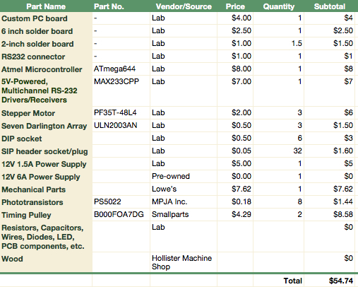
D. Cost Details
E. Task Division
| Task | Group Member |
|---|---|
| Created mechanical design schematics. | Yunchi |
| Created electrical design schematics. | Mengliang |
| Built mechanical part. | Both |
| Soldered ULN2003 circuits and Phototransistor array circuits. | Mengliang |
| Soldered Custom PCB. | Yunchi |
| Wrote image process code. | Mengliang |
| Wrote motor control, A/D converter and serial connection program. | Yunchi |
| Debugged program. | Both |
References
Data Sheets
MAX233CPP — +5V-Powered, Multichannel RS-232 Drivers/Receivers
Vendor Sites
Code/Design Ideas Borrowed from Others
Fischertechnik plotter by Procon Technology
Reference Sites
Special Thanks
We would like to give special thanks to the following people who helped us to finish our final project.
Bruce Land for giving great ECE 4760 lectures about how to use microcontrollers and helping us to solve problems in the lab.
Allison Smyth for helping us in the lab and giving advice on our final project.
Paul Charles at Hollister Machine Shop for kindly providing us with wood and assisting us to build the mechanical part of our project.
Timothy Bond at Harry E. Bovay Jr. Lab for kindly providing us with precious advice on building the mechanical assembly.
Patricia Gonyea of the ECE Department for providing us with screws and letting us borrow a power drill.
Francisco de Castro for his image processing code.