
"A step sequencer drum machine allowing creation and playback of percussion loops containing up to six voices." sound bite

The finished product and its creators. Click to enlarge.
Overview [top]
As avid audiophiles, we wanted to apply our newly acquired knowledge of microcontrollers to build a fun consumer electronic device. Our project is a step sequencer drum machine. The user is able to program a 16-step percussion pattern using one of a wide range of percussion instruments on each of six different tracks. The user toggles between different tracks and different instruments and adjusts tempo through an intuitive user interface consisting of pushbuttons and an LCD display. Configurations can also be saved and loaded from the microcontroller's EEPROM.
High Level Design [top]
Rationale & Inspiration
Wikipedia writes: "A drum machine is an electronic musical instrument designed to imitate the sound of drums or other percussion instruments. They are used in a variety of musical genres, not just purely electronic music. They are also a common necessity when session drummers are not available or desired."
It is common today for drum machines to be purely software devices. Our device is a throwback to 15-20 years ago when hardware drum machines were common. Such hardware drum machines were large, expensive, and clumsy devices. Our device is a modern take on the hardware drum machine. It is inexpensive and features an intuitive and simple user interface.
Our rationale for embarking on this project was to create a fun and interesting electronic musical instrument that could provide enjoyment to even non-musically inclined individuals. In addition to being a fun device, our drum machine could have practical uses. It could be used to complement a solo performance, or as a means of composing electronic music.
We were inspired by the Rhythm Ring, a Spring 2008 ECE 4760 final project by Brian Yung & Hanson Jiang. While we liked the sequencer idea of the Rhythm Ring, we wanted to improve the user interface to mimic an industry standard drum machine which offers a greater amount of control on the number of tracks and instruments to play back, the speed at which to run the sequencer, and the ability to save and load user generated patterns. While searching online, we found a more sophisticated drum machine that we really liked named the Beat707 which is Arduino-based. We based our user interface on their pushbutton and sequencer LED design which was more in sync with industry standard drum machines.
Concept
We set out to create a drum machine in the spirit of the hardware step sequencer drum machines that were prevalent 15-20 years ago and that still exist today. The programming interface is a row or grid of 16 pushbuttons---representing a 16-step musical bar. The user places sounds by pressing the pushbuttons and the created pattern is played back as a sequencer loops through the 16 steps.
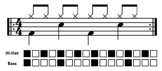
Step sequencer programming and its correspondence to musical notation. Click to enlarge.
In our design we include just one row of pushbuttons. The user programs one of six possible tracks (voices) at a time. LEDs above each step indicate which steps are currently selected. The LEDs also indicate the progress of the sequencer---lighting at the current step if it is not selected in the pattern and turning off it it is (XOR with the pattern).
A control panel of an LCD and up/down/left/right pusbuttons allows the user to change the currently selected track, select instruments for each track, adjust the tempo of the sequencer, and save/load preset configurations. A total of 20 different instruments are available---including typical percussion instruments (bass drums, snare drums, hi-hats, etc) as well as some more electronic sounds. The tempo can range between 60 and 220 beats per minute (BPM). The user can save up to 50 preset configurations---which are stored in the MCU's EEPROM and therefore preserved even when the power is off.
Three additional pushbuttons allow the user to play/pause the sequencer, clear the currently selected track, or clear the entire configuration (the patterns and instruments for all six tracks as well as the tempo) and return it to the default.
Our device plays back digitally sampled sounds at 22,068 Hz stored in the MCU's memory. Audio playback is through a digital-to-analog converter (DAC) and fed to a 3.5mm mono audio jack that is designed to be connected to high-impedance computer speakers.
Logical Structure
Logically the MCU must perform two primary tasks: audio playback and user interface processing.
As mentioned earlier, audio playback is accomplished by having the MCU output audio samples to a DAC. The interface between the two is the Serial Peripheral Interface (SPI) and the samples are output from an interrupt service routine (ISR) running on the MCU in order to maintain accurate output at the desired sampling frequency (22,068 Hz).
User interface processing is a significant task and requires the majority of the hardware and software. In order to reduce the number of I/O pins required, the 23 pushbuttons and 16 LEDs are connected to shift registers and read/driven serially by the MCU. Note there is no hardware connection between the pushbuttons and LEDs---pushbutton input is processed and output to LEDs all in software.
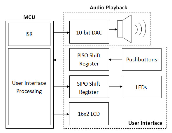
Logical Structure. Click to enlarge.
Hardware/Software Tradeoffs
During the planning stages of this project, we made several high level hardware related decisions. In order to play back audio samples, we decided to use a hardware digital to analog convertor (DAC) rather than software pulse width modulation (PWM). We did this primarily to simplify the software and also because we believed it would improve the overall audio quality.
Another hardware decision we had to make was the size of our LED and pushbutton arrays. Early on we considered using a 16x4 array of LEDs and pushbuttons (one row for each of four possible tracks) and an additional row of 16 LEDs that would show the progress of the sequencer. We quickly realized that this would result in too many wires and connections and the hardware would become unnecessarily complex. Instead we chose to reduce the hardware complexity by using just a single row of 16 LEDs and pushbuttons. Track switching is handled in software. We also merged the sequencer LEDs and pushbuttons LEDs into one single row of LEDs. The sequencer XORs with the pattern as it progress through. This change freed us from being limited to only four tracks by the hardware. Now a change in the software could increase the number of tracks. We decided to implement six tracks in our final device---our original concept contained just four.
We also traded off hardware in favor of software in the design of the control mechanism. Initially, we planned on using dedicated pushbuttons for changing the track and selecting instruments, and a potentiometer for adjusting the tempo. We realized that this would have led to a very cluttered user interface and would lead to challenges if we wanted to implement more complex control functions like the saving/loading of presets. Instead we designed an interactive LCD display showing the currently selected track, instrument and tempo. The LCD also contains a menu option to save/load presets. The user navigates the display and makes changes using up/down/left/right control buttons. The input is all processed in software via state machine. The result is an elegant and easy-to-use user interface.
Standards
We made use of the SPI standard in order to communicate between our MCU and DAC. An additional standard relevant to our design is the IEC 825-1 (International Electromechanical Commission) "Eye Safety Classification of Some Consumer Products" which sets the standard for LED and laser brightness to keep the users' eyes safe from unsafe levels. We met this standard by refraining from using super-bright LEDs and we set the spacing between LEDs keeping this standard in mind.
Existing Patents, Trademarks, & Copyrights
By conducting a non-exhaustive patent search through the Google Patent search engine, we found several patents for music sequencers and rhythm synthesizers. Although these designs use similar ideas of synthesizing prerecorded sounds, they do not share the same user interface or use the same method of using pushbuttons to create a pattern with control over every step. However, since our idea for the drum machine and synthesizer is borrowed from that of commercial synthesizers, there must exist a patent for such a device even though it might have expired by having been filed more than twenty years ago.
We based much of our design on the Beat707 MIDI drum machine produced by Rugged Circuits. Although we did not use any of their code, we were inspired by the way they implemented the drum machine and a sequencer. The Beat707 is still under open-source development and not yet commercially available; there has been no formal patent filed.
We recognize that since our device is not entirely novel, it does not have any patenting or publishing potential. We did not create this device for commercial purposes but rather to apply our knowledge of microcontroller programming to create an interesting device for educational purposes. We do not plan to file a patent for our device nor do we wish to infringe any patents that may have been previously granted to another party. We do not believe that we are infringing anybody's trademarks or copyrights by titling our project the 'Step Sequencer Drum Machine' as a brief Google search did not yield any hits on this particular title.
Hardware Design [top]
Because of the elaborate user interface this project involves a significant amount of hardware. For this reason we approached the hardware design in two phases: a prototype stage and the final assembly. During the prototyping stage, we constructed the entire device on solderless breadboards. Such a prototyping phase allowed us to realize the most efficient wiring schemes and also gave us flexibility to change our design as the software required. It also allowed for easy accessibility to various nodes in our circuit during debugging.
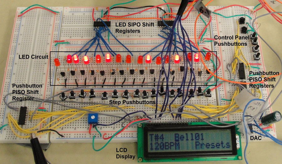
Fully-functional breadboard prototype. Click to enlarge.
To house the Mega644 MCU we used the ECE 4760 custom PCB target board designed by Professor Bruce Land. It contains the microcontroller along with all the necessary power and auxillary circuitry. We power the target board with a 9V battery, and use the MCU's 5V Vcc to power all our other circuitry.
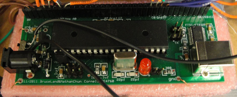
MCU Target Board. Click to enlarge.
In addition to the target board our device contains 3 primary subcircuits: the pushbutton circuit, the LED circuit, and the DAC circuit.
Pushbutton Circuit
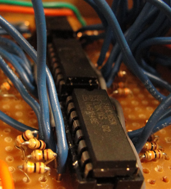
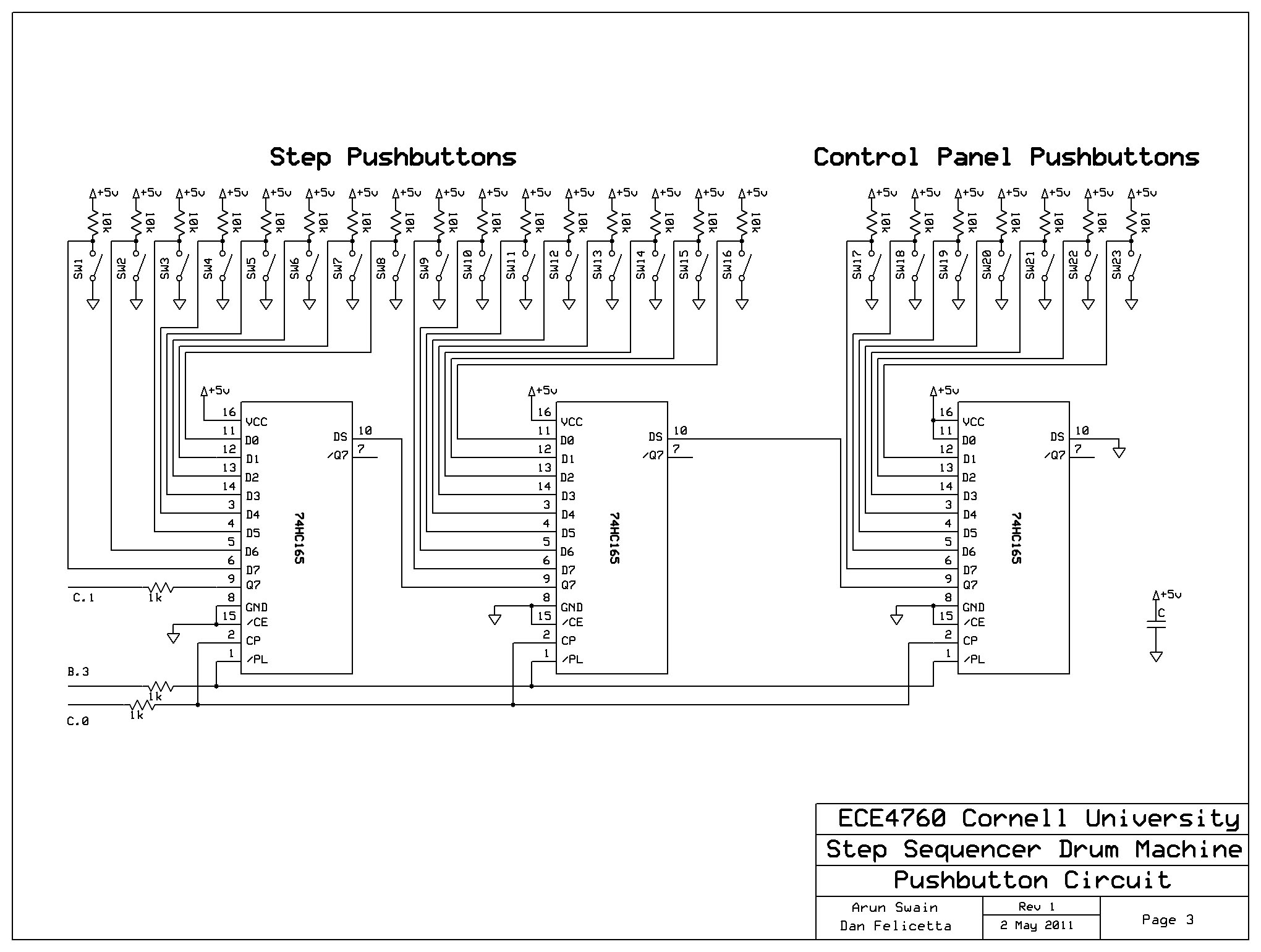
As described earlier, our device contains 23 pushbuttons. Instead of connecting all 23 pushbuttons to individual pins on the Mega644---which would have caused a shortage of pins for our other components---we connect them to three cascaded 74HC165 8-bit parallel-in-serial-out (PISO) shift registers.
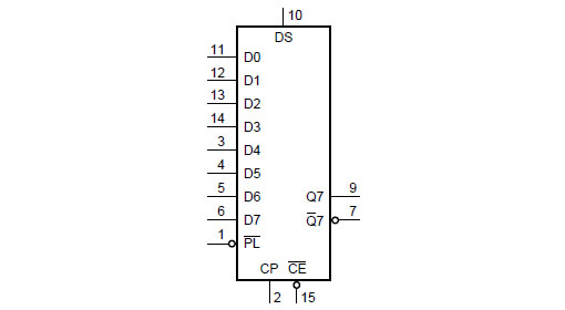
74HC165 Parallel-In-Serial-Out Shift Register
Each 74HC165 contains 8 parallel inputs (D0-D7). These pins are pulled-up to Vcc through a 10 kOhm resistor (to limit the current to the pin) and the pushbutton is connected in a shunt branch to ground. We selected pushbuttons with no bounce. The result is a logic low pulse on the input when the pushbutton is depressed. The 74HC165 loads the input pin values into an internal register when triggered to do so by a logic low pulse on the parallel load pin (1). It then shifts the contents of the register out serially on the output pin (9) when triggered by the clock pin (2). The Mega644 provides the parallel load and clock signals and receives the serial data output (Q7) as input.
Pushbutton Circuit. Click to enlarge.
We tested each pushbutton on the oscilloscope to ensure proper operation. We debugged the daisy chained shift registers by reading 23 bit values for different pushbutton combinations on a PuTTy terminal.
LED Circuit
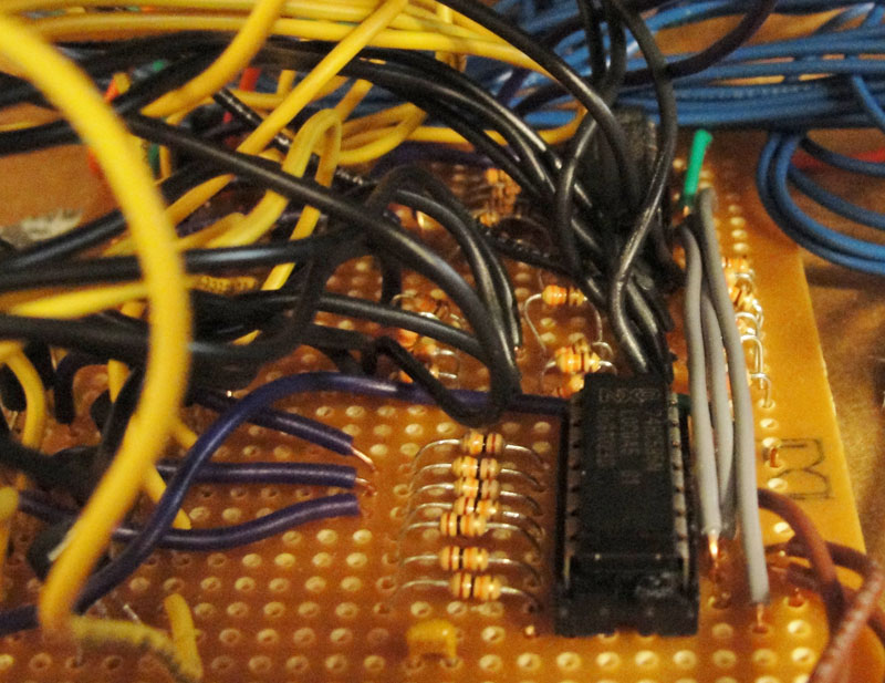
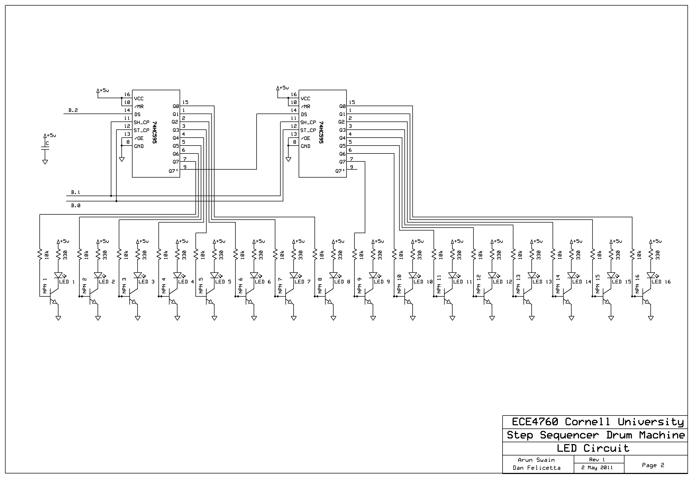
To drive the 16 LEDs we once again employed shift registers to minimize the number of MCU output pins required. In this case we use the dual of the 74HC165, the 74HC595---an 8-bit serial-in-parallel-out (SIPO) shift register. We cascade two to drive the 16 LEDs.
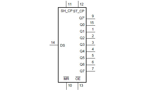
74HC595 Serial-In-Parallel-Out Shift Register
The 74HC595 receives data serially from the MCU on the DS pin (14), shifting it into the internal 8-bit register based on the shift clock (12). Once all the data has been shifted in a logic low pulse on the storage clock pin (12) causes the register contents to be dispensed to the output pins (Q0-Q7).
Each output pin switches on/off an NPN transistor with the LED and a 330 Ohm resistor to Vcc in the collector and the emitter grounded. A 10 kOhm resistor between the 74HC595 output pin and NPN base limits the base current. When the NPN is on the collector current is sufficient to brightly light the LED.
LED Circuit. Click to enlarge.
We tested the LEDs for brightness and correct operation. We also tested the order of our arrangement and connections with the shift register by driving various 16 bit values on the LEDs and checking for correctness.
DAC Circuit
In order to play back the digital audio samples stored in the MCU's program memory through a speaker, a DAC is used. We use a 10-bit DAC from Maxim (MAX515) with an SPI interface.
The Mega644's SPI_MOSI pin (B.5) connects to the DAC's data-in pin (1) and the SPI_CLK connects to the clock input (2). Both pass through 1 kOhm resistors to limit current. MCU pin B.4 drives the DAC chip select (3).
The DAC is confgiured to output an analog voltage between 0 and 5V. For a binary input b ranging from 0 to 1024 the output is b/1024 * 5V. In order to drive a speaker a bipolar output voltage is required so a large capacitor (330 uF) is connected in series with the output to remove the DC offset.

DAC Circuit. Click to enlarge.
Upon testing audio playback of sampled sounds, we were satisfied with the quality of audio output by the DAC.
LCD Display
A 16x2 LCD is connected to the Mega644's PORT D.
Final Assembly
Upon the conclusion of our test and debug phase with the prototype, we progressed onto the final assembly. In order to give our drum machine a more professional look and appear less like a hurried student project, we decided to package everything into a cardboard box with the pushbuttons, LEDs and the LCD display protruding through holes cut in the box. The pushbutton, LED and DAC circuits were all constructed on two solder boards and carefully nestled inside the box neatly along with the target board. We also connected the audio output from the capacitor to a 3.5mm mono audio jack for easy connectivity with PC speakers. We also soldered a large ON/OFF rocker switch onto the target board which protrudes through the cardboard box's side to allow the device to be powered on and off. The entire device is powered by a 9V batter contained in the box.
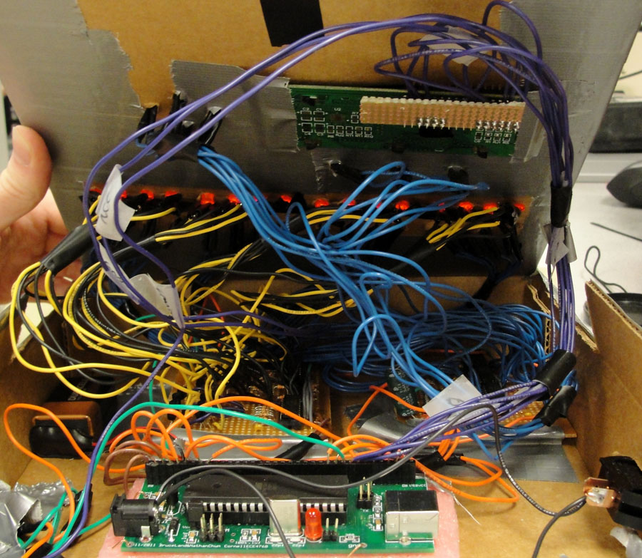
Inside the box. Click to enlarge.
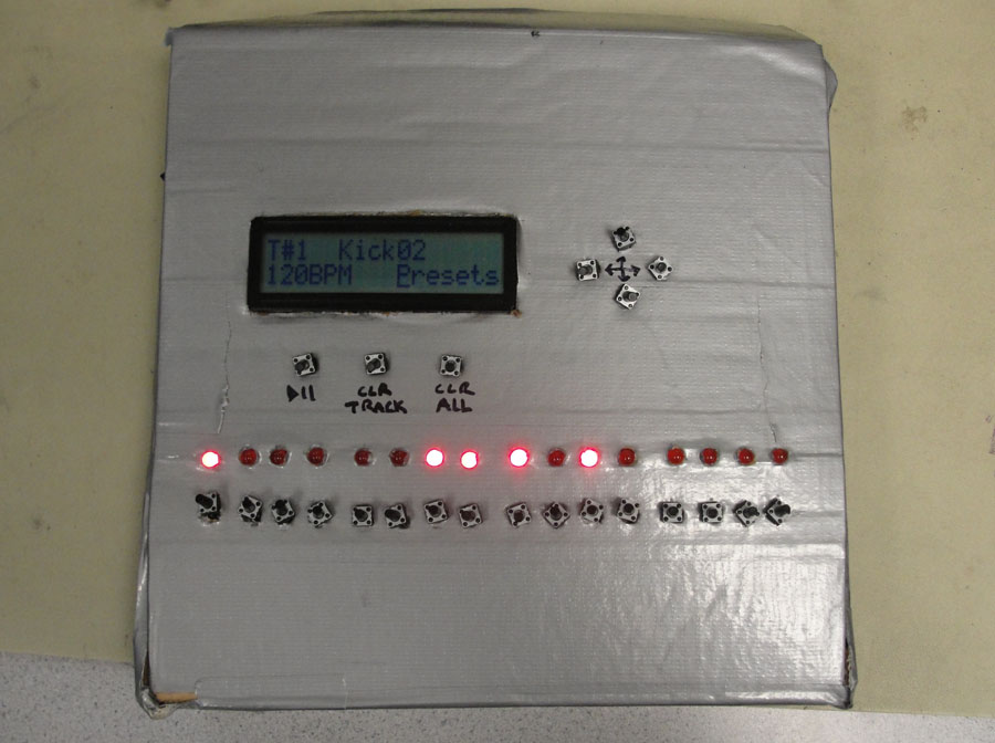
The box closed. Click to enlarge.
See Appendix B for schematics showing all the wiring schemes in detail. Any individual familiar with electronic assembly could replicate our final project easily.
Software Design [top]
The software for this project must manage human interaction with a dynamic and complex user interface and at the same time meet the real-time requirement of continously playing back multiple tracks of audio at precisely timed steps. What follows is a description of how our software meets these requirements.
WAV to C Conversion
As mentioned earlier, our drum machine plays back pre-recorded percussion sounds at a 22,068 Hz sampling rate. These sounds were downloaded from the internet as WAV files. The MCU obviously cannot playback WAV files directly, so this necessitates some method of converting from the WAV files to a compact representation that can be placed in the MCU memory.
For this we turned to MATLAB and wrote a script (wav_conv.m) that takes WAV files and automatically generates a C header file that instantiates data structures which completely represent the sounds in memory. The input WAV files can have a sampling rate of either 22 or 44 kHz. 44 kHz files are downsampled to 22 kHz using the MATLAB function decimate.
The sounds themselves are represented in C as unsigned char arrays stored in the MCU's program memory. The sample values therefore must range from 0 to 255. In order to stay within the 10-bit range of our DAC when samples from all six tracks are played simulataneously we narrow the range to be from 0 to 1024/6 = 170. The MATLAB function wavread reads a WAV file into a one-dimensional array containing values ranging from -1 to 1, so the conversion to an array of values ranging between 0 and 170 is straightforward:
y = wavread('sound.wav');
conv_y = floor(.5*170*(y+1));
After the conversion the MATLAB script also multiplies the new sample values at the beginning and end by a linear ramping function. This improves the sound quality during playback.
The MATLAB script additionally writes string constants for each sound to be displayed on the LCD when that particular sound is selected. These strings come from the filenames of the input WAV files.
In addition to the arrays and strings representing each sound, the MATLAB script also creates three arrays to represent the set of N sounds, each of length N. The sample array contains pointers to the arrays containing the sample values for each sound. The sample_text array contains pointers to the string description for each sound. Finally, the sample_len array contains the number of samples for each sound. These three arrays allow the code running the MCU to interact generically with any set of sounds included in the header file---which allows the set of sounds to be easily changed simply by swapping the header file.
See samples.h for an example of header file output by the MATLAB script.
Audio Playback
As described earlier, audio playback is done through a 10-bit digital-to-analog Converter (DAC). The MCU must output sample values to the DAC at the correct sampling rate (22,068 Hz) through the SPI interface. The natural choice to accomplish this task is an interrupt service routine (ISR). The Mega644's timer 1 is configured to run a compare-match ISR at approximately 22 kHz. The ISR accumulates the current sample value from the six possible tracks and sends this value to the DAC over SPI:
// Audio Playback ISR (22 KHz)
ISR (TIMER1_COMPA_vect)	{
    audio_out = 0;

    if ((play_track & TRACK1) && sample_count[0] < sample_len[settings.sound[0]])
        audio_out += (pgm_read_byte(&(sample[settings.sound[0]][sample_count[0]++])));

    if ((play_track & TRACK2) && sample_count[1] < sample_len[settings.sound[1]])
        audio_out += (pgm_read_byte(&(sample[settings.sound[1]][sample_count[1]++])));

    if ((play_track & TRACK3) && sample_count[2] < sample_len[settings.sound[2]])
        audio_out += (pgm_read_byte(&(sample[settings.sound[2]][sample_count[2]++])));

    if ((play_track & TRACK4) && sample_count[3] < sample_len[settings.sound[3]])
        audio_out += (pgm_read_byte(&(sample[settings.sound[3]][sample_count[3]++])));

    if ((play_track & TRACK5) && sample_count[4] < sample_len[settings.sound[4]])
        audio_out += (pgm_read_byte(&(sample[settings.sound[4]][sample_count[4]++])));

    if ((play_track & TRACK6) && sample_count[5] < sample_len[settings.sound[5]])
        audio_out += (pgm_read_byte(&(sample[settings.sound[5]][sample_count[5]++])));

    // send audio_out to 10-bit DAC on SPI
    PORTB &= ~(1<<PINB4); // B.4 (DAC /CS)
    SPDR = (char) ((audio_out >> 6) & 0x000f); //byte 1 0 0 0 0 b9 b8 b7 b6
    while (!(SPSR & (1<<SPIF)));
    spi_junk = SPDR;

    SPDR = (char) ((audio_out & 0x003f) << 2); //byte 2 b5 b4 b3 b2 b1 b0 0 0
    while (!(SPSR & (1<<<SPIF)));
    spi_junk = SPDR;
    PORTB |= (1<<PINB4);
}
Representing State
As the user programs the drum machine (selecting instruments and programming patterns for each track) he/she creates a unique configuration of the state of the machine that must be represented in the software. The complete configuration can be represented by three things:
- Six 16-bit bitmaps representing the currently selected sequencer steps for each track
- The six indices of the currently selected instruments for each track
- The current tempo (BPM)
The natural way to represent this state information in software in to use a C structure. The setting stucture contains a length 6 array of type int containing the sequencer bitmaps for each track, a length 6 array of type char containing the indices of the selected sound for each track, and a char field for the currently selected tempo (in BPM):
typedef struct setting {
    uint16_t seq_bmp[NUM_TRACKS]; // bitmaps for each track
    uint8_t sound[NUM_TRACKS]; // sound id for each track
    uint8_t bpm;
} setting;
Timing
The MCU must maintain an accurate timebase in order to run the sequencer and poll/update the user interface. For this purpose the Mega644's timer 0 is configured to generate an interrupt every half millisecond. The corresponding ISR updates two timer variables---one for the sequencer (seq_timer) and one for user interface polling (input_timer).
A half millisecond timebase was chosen to provide a tempo resolution of 1 beat per minute (BPM). Here we use the common musical notion that one "beat" is one quarter note. In the context of our drum machine this corresponds to four sequencer steps---as each sequencer step represents 1/16th of a measure.
For the sequencer the relevant time is the number of half milliseconds between steps. In terms of the user-input BPM this is (1/(bpm/60)*4)*2000 = 30000/bpm.
Sequencer
Running the sequencer in software is straightforward. main() calls a function do_step() at the interval calculated above. do_step() increments the step number and updates the LEDs to light the next in the sequence. It also updates the play_track flags---which indicate to the audio playback ISR which tracks should be played at a particular step.
LED Updating
As described above, 16 LEDs represent simultaneously the state of the sequencer as well as the user-input pattern for the currently selected track. The LEDs are driven serially through serial-in-parllel-out (SIPO) shift registers by the MCU. These LEDs must be updated by the software at each sequencer step, as well as after the user pushes any of the step pushbuttons. The led_update() function performs this task---sending the current LED configuration to the 74HC595 shift registers by bit-banging:
/*
 * Update the LEDs
 * Data is sent to the two 74HC595s by bit-banging
 */
void led_update()	{
    for (i=0; i<16; i++)	{
    // LED lights on sequencer step and XORs selected steps
    if (((settings.seq_bmp[current_track] ^ (1 << step_number))>>i) & 0x1)
        PORTB |= (1<<PINB2);
    else PORTB &= ~(1<<PINB2);

    // pulse the shift clk
    PORTB |= (1<<PINB1);
    PORTB &= ~(1<<PINB1);
    }
    // pulse the storage clk
    PORTB |= (1<<PINB0);
    PORTB &= ~(1<<PINB0);
}
The software sets pin B.2 to the current data bit and then pulses the shift register clock on pin B.1, which shifts the data left 1 bit. When all 16 bits have been shifted in, the storage clock (pin B.0) is pulsed which causes the shift register to transfer the register contents to its output pins which are connected to the LED driver circuitry.
User Interface
One of the most complex functions of our software is to process user input from the drum machine's 23 pushbuttons. The pushbutton input is output from 3 cascaded 74HC165 parallel-in-serial-out (PISO) shift registers and enters the MCU serially. This serial input is polled by the software every 75 milliseconds. This polling period was selected through experimentation. If it is too small the UI polling interferes with the sequencer timing and if it is too large the pushbuttons are not responsive to rapid input changes.
The scan_butons() function is run by main() at the selected polling period. The serial input is read once again by bit-banging. Two seperate variables seq_button_scan and ctrl_button_scan record the current scan of the pushbuttons. We perform a bitwise AND between these values and the negated values from the previous scan in order to identify a rising edge (the pushbuttons are configured as active low). Action is taken only when a rising edge is detected (when the pushbutton is released).
For the step pushbuttons (1-16) the action is to toggle the corresponding bit in the pattern for the current track.
The action of the first three control pushbuttons (17-19) is straightforward. The first toggles a flag which plays or pauses the sequencer. The second clears the pattern for the current track and the third clears the entire programmed configuration and returns it to the default.
The remaining four pushbuttons (20-23) together with the LCD provide control over track, instrument, and tempo selection, as well as saving/loading of presets. The pushbuttons have up/down/left/right functions and the action taken when they are pressed is determined by a state machine. The user is made aware of the state by looking at the LCD---the position of the underline cursor and the text indicate the control state and therefore the actions that the up/down/left/right buttons will have. The control state machine can be described by the following state transition diagram:
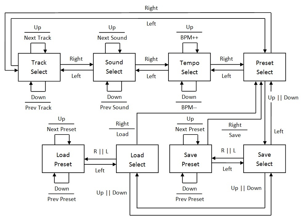
User Interface Control State Machine. Click to enlarge.
Presets
Our step sequencer drum machine has the added capability of being able to store user-created presets. For this we utilize the Mega644's EEPROM, which allows the data to be perserved even when the drum machine power is off. As mentioned earlier a user-defined configuration is represented in code as a C structure. Structures in C are stored in contiguous blocks of memory and this makes saving and loading presets to and from the MCU EEPORM simple. An array of presets is delcared to reside in the EEPROM using the EEMEM compiler directive:
setting EEMEM presets[NUM_PRESETS];
The AVR EEPROM library provides two functions for reading and writing blocks of EEPROM memory---eeprom_read_block and eeprom_write_block. Each takes a pointer into RAM, a pointer into the EEPROM, and a number of bytes to be read or written. For a read, the block of data in EEPROM is transferred to the block in RAM. Our code loads a preset with the following line:
eeprom_read_block((void*) &settings, (const void*) &(presets[preset_load_num]), sizeof(setting));
Similarly for a write, the block of data in RAM is transferred to the EEPROM. We write presets with the following line:
eeprom_write_block((const void*) &settings, (void*) &(presets[preset_save_num]), sizeof(setting));
Our drum machine comes preloaded with four demo presets that cannot be overwritten.
Results [top]
Our step sequencer drum machine works really well. It is responsive to the user input and easy to use. Even people who are not musically-inclined can easily compose interesting and fun percussion loops.
Six different voices each featuring one of 20 possible instruments can be played back simultaneously. We chose six tracks to strike a balance between the audio quality and the compositional complexity available. The 20 sampled sounds together with our program code occupy 78.6% of the Mega644's 64KB program memory.
Tempo can be varied from 60-220 BPM---the typical range of most music. There is the ability to save/load 50 preset configurations in the MCU's EEPROM. Four of these are preprogrammed demo presets that cannot be overwritten.
Overall, we had good quality audio samples using the 10-bit DAC which we were quite pleased with. We measured the audio quality of the tracks by ear and by examining the waveform using the oscilloscope. Playback waveforms captured on an oscilloscope are shown below.
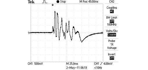
Bass Drum
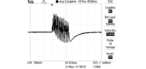
Bell

Pattern Playback
We did have some issues with some sounds we attempted to play back. In the conversion from the downloaded WAV file to the representation in MCU memory, too much information was lost and the sound quality became poor and we began to hear distortion and clicks. We selected a set of sounds that we feel playback at the best quality and applied a ramping function in our MATLAB WAV to C conversion script to smooth the overall sound quality.
Our device does exhibit one "glitch"---but we do not consider it to affect the overall functionality of the drum machine. If the user begins rapidly changing the instrument for the currently selected track, sequencer playback slows down slightly. The cause is obvious---the user interface processing portion of the code is pushing back the scheduling of the sequencer routine. The sequencer picks back up at the correct tempo as soon the user settles on an instrument. We find this behavior to be acceptable as playback during rapid instrument changes is neither a necessary nor useful feature.
Safety
To make our drum machine safe, we decided to package everything into a box so that we did not have any exposed wires. We also covered up any exposed copper on the ends of our stripped wires with electrical tape to prevent any shorts from occurring when the wires move around when the box is opened or closed. We also put a large ON/OFF switch on the outside of the box so that there will be no reason to ever open the box for normal usage which minimizes any disturbance to the wires inside.
User Friendliness
Finally, we have designed our step machine in such a manner so that it is very intuitive and easy to use. We do not anticipate anyone having any difficulty operating it. However as with any visual or auditory instruments, our drum machine will not be useful or operable fully by those who are blind, deaf, or paralyzed since we require the user to be able to visually recognize patterns on the LEDs and accordingly push buttons, which yield different sounds for the user to appreciate. Outside this small group of disabled individuals, we do not anticipate the common person to have any difficulty operating this device.
Conclusions [top]
At the onset of this project, we drafted a proposal specifying the functionality and design of our drum machine. We had envisioned what the user interface would look like and how the device would behave. Looking at the final outcome of our project, we are pleased to report that we met all these specifications and that the final device exceeded our own expectations.
We met our expectations of controlling individual steps of different instruments on a per track basis with pushbuttons for all 16 steps and simultaneously altering the state of the LED while playing back the correct sampled sound.
We exceeded our expectations regarding the user interface by creating an interactive LCD control panel which is navigable and makes the device easy to use. We also added the ability to save user generated configurations to the MCU's EEPROM as presets. This allows them to be preserved even when power is off.
All in all, we have engineered a fun and interactive consumer electronics device that allowed us to practically apply many of the concepts learned in ECE 4760 and our other electrical engineering courses.
Future Improvements
Some future improvements might include improving aduio playback with a higher resolution DAC, expanding the set of available sounds using an external EEPROM, and adding MIDI connectivity. An additional improvement could be adding USB connectivity and development of a real time interface with an application that allows the user to add new audio samples directly from a PC. This improvement would be a bit time consuming but would allow the user to customize the drum machine further. We could also envision improving the aesthetics and durability of the enclosure.
If we had to do this project over again, we would opt to construct our circuits on a custom PCB. The sheer multitude of dangling wires made it difficult to place everything inside a cardboard box without breaking connections.
Conformity to Standards
We conformed to the Serial Peripheral Interface standard in using it to communicate between the MCU and DAC. We also conformed to the the IEC 825-1 (International Electromechanical Commission) "Eye Safety Classification of Some Consumer Products" standard by using LEDs that do not exceed acceptable brightness levels.
Intellectual Property Considerations
We do not feel we have infringed on any individual's intellectual property by creating our drum machine. We have credited the Rhythm Ring as inspiration. We did not use any of their code or design. We have also credited the Beat707 as inspiring the design of our user interface. We did not use their code and feel our design is distinct enough such that it does not infringe on their intellectual property. The only code that is not our own is the LCD library from Scienceprog.com, which is available in the public domain.
Devices similar to what we have created have been made and are comercially available so we therefore do not foresee any patent or publishing opportunities. Our project is for educational purposes and we do not intend on selling it comercially.
IEEE Code of Ethics
Abiding by the IEEE Code of Ethics, we worked on this project in an ethical manner to create a final product free of ethical violations. We accepted responsibility that our drum machine would not harm others. For this reason, we abided by the IEC 825-1 "Eye Safety Classification of Some Consumer Products" when choosing which LEDs to use and how far to spread them apart to avoid harming the user's vision with super-bright LEDs. We also tucked away all the wires neatly into a box to prevent the user from coming in contact with any exposed wire while the device is turned on.
We have also never claimed false results or tried to conceal any shortcomings of our device in this report and have been perfectly honest in stating our claims. We have also given credit where due, for instance to Bruce Land, for using his custom PCB target board. We have also acknowledged that we were inspired by Brian Yung and Hanson Jiang's Spring 2008 Rhythm Ring final project and Rugged Circuits' Beat707 drum machine. We have disclosed that we do not have any conflicts of interest in terms of existing intellectual property. We have also credited our vendors for their parts in Appendix D and Maxim for sampling the MAX515 DAC to us. In the collegial spirit, we have also helped our peers whenever they had any questions related and unrelated to our project to the best of our abilities without any discrimination. By working on this project and applying our knowledge of embedded programming, we have sought to increase our technical knowledge and hope that it creates a useful and enjoyable product. For the aforementioned reasons, we believe we have embodied good ethical conduct as outlined by the IEEE Code of Ethics.
Legal Considerations
We do not violate anyone's intellectual property rights nor does our drum machine cause harm to others. The drum machine also does not interfere with any other electronics but rather is a self contained system which runs on a 9V battery to blink several LEDs, display text on an LCD screen, and play back audio sampled sounds. Since we do not broadcast any RF signals, we need not be concerned with FCC regulations. Therefore, our project is in compliance with current legal standards.
Appendix A: Code [top]
wav_conv.m- MATLAB WAV to C conversion scriptdrum_machine.c- MCU drum machine codelcd_lib.c,lcd_lib.h- LCD library (From Scienceprog.com)samples.h- MATLAB generated header file containing audio sample data
Appendix B: Schematics [top]
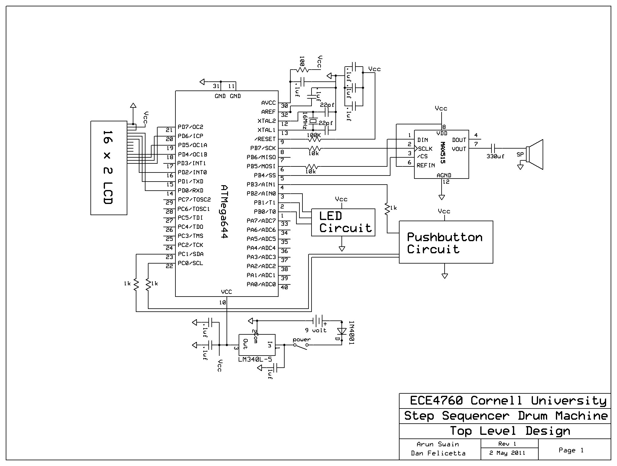
Schematic Page 1 - Top Level. Click to enlarge.
Schematic Page 2 - LED Circuit. Click to enlarge.
Schematic Page 3 - Pushbutton Circuit. Click to enlarge.
Appendix C: Parts [top]
| ITEM | SOURCE | UNIT COST | QUANTITY | TOTAL COST |
|---|---|---|---|---|
| TOTAL | $40.65 | |||
| Atmel ATMega644 | Lab | $8.00 | 1 | $8.00 |
| 10-bit DAC (MAX515EPA+) | Maxim | Sampled | 1 | $0.00 |
| 8-bit PISO Shift Register (74HC165N) | Digikey | $0.72 | 3 | $2.16 |
| 8-bit SIPO Shift Register (74HC595N) | Digikey | $0.94 | 2 | $1.88 |
| Pushbutton (EVQ-21509K) | Digikey | $0.21 | 23 | $4.74 |
| Red LEDs | Lab | $0.00 | 16 | $0.00 |
| NPN BJT (2N3904) | Lab | $0.00 | 16 | $0.00 |
| 16x2 LCD | Lab | $8.00 | 1 | $8.00 |
| Solder Board (Large) | Lab | $2.50 | 2 | $5.00 |
| Solder Board (Small) | Lab | $1.00 | 1 | $1.00 |
| DIP Socket | Lab | $0.50 | 6 | $3.00 |
| Header Pins | Lab | $0.05 | 65 | $3.25 |
| Rocker Switch | Digikey | $0.58 | 1 | $0.58 |
| 3.5 mm Mono Audio Jack | Digikey | $1.04 | 1 | $1.04 |
| 9V Battery | Wegmans | $2.00 | 1 | $2.00 |
| Cardboard Box | Previously Owned | $0.00 | 1 | $0.00 |
| Wires, Resistors, & Capacitors | Lab | $0.00 | Several | $0.00 |
| 9V Battery Snap | Lab | $0.00 | 1 | $0.00 |
Appendix D: Work Division [top]
| Dan Felicetta | Both | Arun Swain |
|---|---|---|
| Software Design | Hardware/Software Debugging | Hardware Design |
| MATLAB Code | Project Idea Research | Parts Ordering |
| Final Assembly | Website Content | Prototype Assembly |
| Website Design | Schematics |
References [top]
- Datasheets
- Inspiration
- Vendors/Manufacturers
- Other References