Software Design
Distance Sensing Control
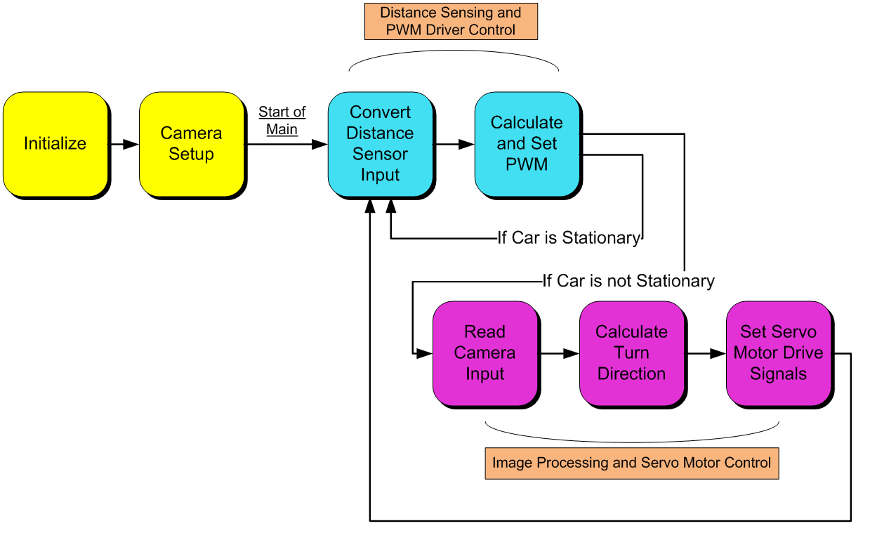
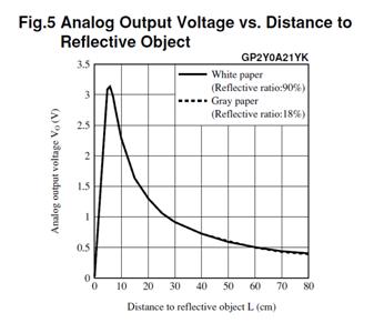
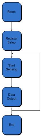
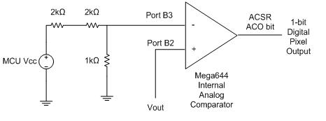
All of the distance sensing code is contained within a function called speedTask(). The function begins by writing to the ADC Start Conversion bit (ADSC) of the ADC Control and Status Register A (ADCSRA) to sample the analog input from the distance sensor and begin a conversion. The ADC takes 13 ADC clock cycles to complete a conversion during normal operation. With our 20MHz clock and a prescaler of 128, the ADC clock runs at 156.25kHz. The conversion time required is thus 83.2us. To ensure proper operation of the ADC in speedTask(), a hardware delay is implemented right after the conversion begins. After the conversion is complete, the high byte of the ADC result that is stored in register ADCH is compared to a threshold value which determines whether the car is too close or not. The value in ADCH ranges from 0 to 255 with higher numbers meaning that a forward object or obstacle is closer. The control algorithm is a simple if-else construct that contains three different conditions. If ADCH is greater than the threshold value, meaning that the car is too close to something, the PWM duty cycle is set to a value(stopDrive) that stops the car and a flag is set that tells the rest of the program that the car is stationary. This flag is cleared in the other two conditions. If ADCH is not greater than the threshold and the current PWM duty cycle is too low, the PWM duty cycle is adjusted with a higher-than-normal value(jumpDrive) that is intended to jump-start the car from its stationary state. If these two conditions fail, then the car undergoes normal operation and the PWM duty cycle is set to its normal operation value(normalDrive). All of these values � ADCH threshold, stopDrive, jumpDrive, and normalDrive had to be fine tuned adjusted repeatedly in order to find the desired system response. These values proved difficult to calibrate at times when the battery sources we were using dropped in voltage over time.
Camera
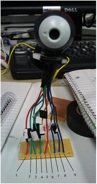
We use software to generate a lot of our input signals to the camera: Only Xck is generated by hardware; the rest are generated by software. Most of the camera functions are used to generate input signals to the camera for initialization and has nothing to do with the main bulk of our program. Of the camera functions, only the function camRead, a function that reads and records the output from the comparator, is in the main bulk of the program. We used state machines for many of these functions to assert and lower registers at edges of our hardware clock. We know for sure that the timing of these state machines are correct because the camera clock speed is slow enough so we have enough time to produce the inputs to the camera accurately. In general, the camera functions cannot be interrupted so there are no interrupts in our code except for the generation of the clocks. We tried using flags instead to implement this but it turned out way too complicated and contained many coding errors. In the end, we got our state machine implementation to work so we decided to stick with this implementation. The flag implementation would probably have saved us a lot of computation time, but computation time is not a huge issue in our project so to us the best design is the one that works.
Picture Array
In order to store the 128 by 123 pixel camera image on the MCU�s memory, we had to compress each pixel from a byte of data, with information about the intensity, to a single bit, which represented only black and white. With this compression, we created a 1968 element char array, where each array element held the information of 8 adjacent pixel bits. The array only takes about 52% of the MCU�s memory, leaving more than enough memory for the rest of the storage required by our code. Unfortunately, the optimization requires a bit more logic for storing and retrieving pixel information.
storePixel
The function storePixel() stores a single pixel bit in the correct picture array element when given the proper x and y locations of the pixel from the camera Vout input. The array is organized as followed. Each horizontal picture line spans 16 consecutive array elements. Since each element stores 8 pixels, 16 elements stores 128 pixels appropriately. In order to store the entire picture, we need 123 lines, or 123*16 = 1968 bytes, or array elements.
Therefore, to store a pixel, the function requires as inputs the pixel data, the x location, and the y location. Based on the x and y locations, storePixel() calculates the appropriate array pointer and shifts in the pixel data into the proper position of the element�s byte of data.
getPixel
The function getPixel() returns the desired pixel value when given the proper x and y locations of the pixel from the camera Vout input. Based on the x and y locations, getPixel() calculates the appropriate array pointer and returns the pixel data at the proper position of the element�s byte of data.
camReset
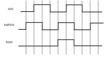
The function camReset is used to reset the camera. The RESET input from the camera requires that we have an active low signal that is detected at the positive edge of the camera clock Xck. We generated another clock halfXck in our ISR for changing signals between edges of the camera clock so that the camera can detect them at the edges of the camera clock. So using the halfXCK, our camReset function works as follows.
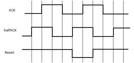
As shown in the timing diagram above, Reset is lowered when halfXCK is high and set back to high when halfXCK is low. We can see that this ensures that the Reset signal will be seen at the positive edge of XCK. The following is our actual state machine for this function.
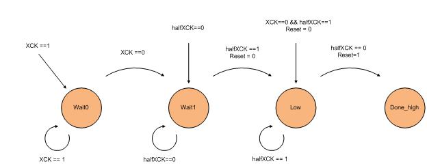
Basically, we want to set the reset signal low either at positive edge of halfXCK or right before the positive edge of XCK when XCK is 0 and halfXCK is 1 and we want to set it back to high at the negative edge of halfXCK. So before we lower the reset signal, we will wait in either Wait0 or Wait1 to wait for the positive edge of the clock. We change the signal Reset while we are changing states to ensure that it is consistent with our timing. We will then wait in the Low state until the negative edge of halfXCK and then set the reset signal high again.
setCamReg
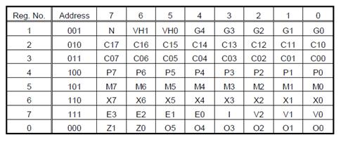
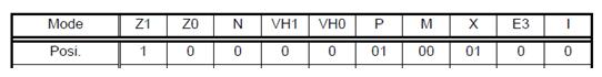
The function setCamReg is used to set our registers. It takes an array of register values as the parameter and sets the SIN and LOAD inputs to the camera based on these register values. Using the register values that we have found in the Hardware section, we created the following array where index 0 corresponds with register 0 and so on.
unsigned char whiteFloors[8]= {0x80, 0x15, 0x00, 0x60, 0x01, 0x00, 0x01, 0x22};
We change the value in index 3 of this array manually to adjust exposure time. In the above array, we adjusted to the lighting on the white floors of Phillips 238. Notice that this value is 0x60. If we change locations to work at the lab benches in Phillips 238, the lighting gets significantly worse and we have to change this value to 0xf0. In general, to adjust lighting, we increase the exposure time when the picture is too dark (contains too much black) and decrease exposure time when the picture is too bright (contains too much white).
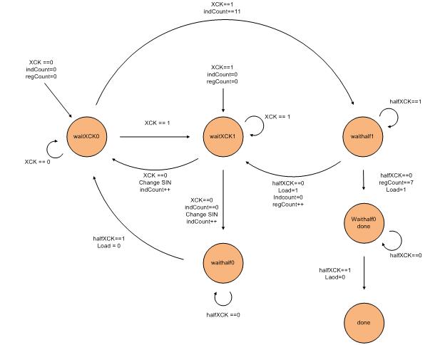
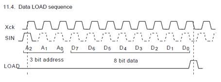
SetCamReg controls the SIN and Load inputs to the camera. The camera needs to be able to detect the address and register values in SIN on the positive edge of XCK and detect Load on the negative edge of XCK after one register have been set. As shown in the Hardware section, below is the data that the camera expects from the SIN and the Load signal.
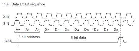 Pg. 9 of Datasheet. Loading one register.
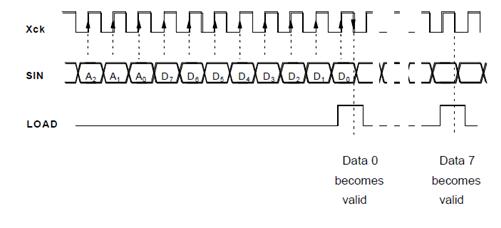
SIN has to first output the values of the address bit by bit then output the register values. After the last register value is set for one register, we have to assert load to be detected on the negative edge of XCK. All of this occurs 8 times since we have 8 registers. To provide the correct timing for all of this in setCamReg, we used the following timing diagram.
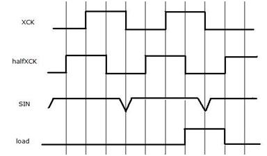
The timing diagram above shows the last 2 data values of SIN being set for one register and shows the load getting asserted when halfXCK is 0. We change the value of SIN at the negative edge of XCK to ensure that the positive edge of XCK will detect the correct value. Load is asserted when halfXCK is 0 to ensure XCK will detect Load on the negative edge. We implemented this using the following state machine.
initStart
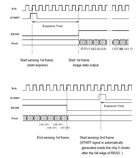
The function initStart is used to send the start signal to the camera to start image capture. This function can only be called after we have called the functions camReset and setCamReg and this function should only be called once. The START input for the camera is an active high signal that needs to get detected at the positive edge of XCK. This is exactly the same as the camReset function except that Start is active high instead of active low. The timing and state diagrams are as follows.
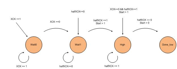
As seen, the timing diagram and the state diagram are identical to the camReset ones except that Start is active high.
camRead
The camRead function waits for a positive edge of the READ output signal from the camera and stores the value from the comparator into our array, Picture, using the function storePixel at every negative edge of XCK until we have stored every value up to and including the line number determined by the macro lastLine. Data is being fetched at the negative edge of XCK because the camera updates the output data Vout on every positive edge of XCK, so we fetch at the negative edge to ensure accuracy. We need to detect a positive edge because we need to know exactly what we are fetching. After read is asserted by the camera, the camera will output the frame pixel by pixel starting from the first line. The state machine for this function is the following.
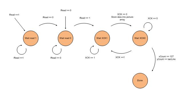
As shown above, we wait for the positive edge of Read, which is reached when we change from state Wait read 0 to Wait XCK1, and we continuously loop between the states Wait XCK 1 and Wait XCK 0 to detect the negative edge of XCK to store our data until we are finished.
Algorithm
When designing our algorithm to detect proper turning conditions, we had to consider various factors due to constraints presented by the microcontroller. Specifically, we want an algorithm that�s accurate and precise, yet uses minimal processing time and memory. In the end, we want our algorithm to have the following properties. First, it must be as simple as possible. In order to minimize memory usage, the code should use as few variables as possible, and avoid arrays or large data structures. Also, the less code there is, the faster the algorithm will complete, reducing delay time between pictures. Second, the algorithm must be efficient. Our algorithm will not need the entire picture array to determine the proper turning condition. This allows us to exit camRead() as soon as we�ve sampled all the picture lines that we need. Finally, it needs to be flexible. The code needs to be easily adjustable for different lighting conditions and camera angles, which helps us debug and calibrate our car.
Following these guidelines, the pseudocode for the turning algorithm is as follows.
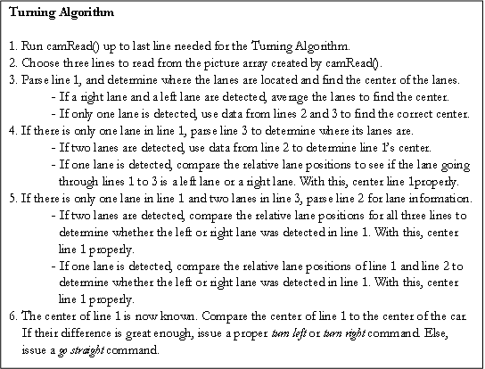
The algorithm is broken down into three main parts: finding a lane, finding the center, and issuing the turning command. Each part will be explained in detail in the following section.
Finding a Lane
Functions leftLaneLoc() and rightLaneLoc() return the relative positions of a potential left lane or a potential right lane, given a line number to parse from the picture array. The functions work as follows, assuming we are looking for a black lane on a white floor.
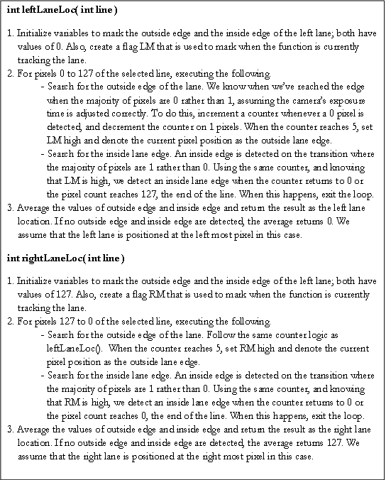
The lane finding functions follow a few simplifying assumptions. First, we assume that the picture taken will only show pixels of value 1 for the floor, and pixels of value 0 for the black lanes. Though the counter in the functions helps adjust for noise, we assume that we have chosen a proper camera exposure time that allows for proper contrast to detect lanes and lanes only. Also, the functions only finds potential left and right lanes; it may be true that leftLaneLoc() and rightLaneLoc() both detect the same lane as both a left and right lane. We left the centering code properly decipher this issue. Finally, The locations found for each lane is a relative center of the lanes, offset by some value due to the counter functionality. This offset may affect the accuracy of the centering code. Fortunately, since both the right lane and left lane have the same offset, the offsets cancel out if we average the left lane location and right lane location when we find the center.
Finding the Center
Following the algorithm�s pseudocode, we let the center of line 1 be the center on which we determine the turning condition for. In order to properly detect the center of a line when there is only one lane, we use 2 additional picture lines and their lane information to interpolate how the lane looks like, rather than inefficiently parsing through the entire picture array. To handle this task, we created a function called turningAlgoSimple() that returns a char representation of the turning state. The function works as follows, assuming the index for line 1 < index for line 2 < index for line 3.
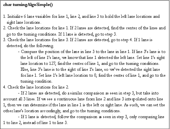
For this code, we make the following assumptions. First, we assume that line 1 is the furthest sample we care about, and line 2 and line 3 are points closer to the camera, hence the larger y axis offset. Second, we assume that all three samples are relatively close to each other. Doing this allows us to ignore some corner cases which would invalidate our algorithm. Also, it would be unnecessary to have too large of a line offset between 2 samples, as accuracy would not improve and the execution time of the algorithm will increase due to a longer camRead(). Finally, we assume that the offset used to determine the number of lanes detected is properly adjusted for the current camera exposure time and the camera angle.
Issuing the Turning Command
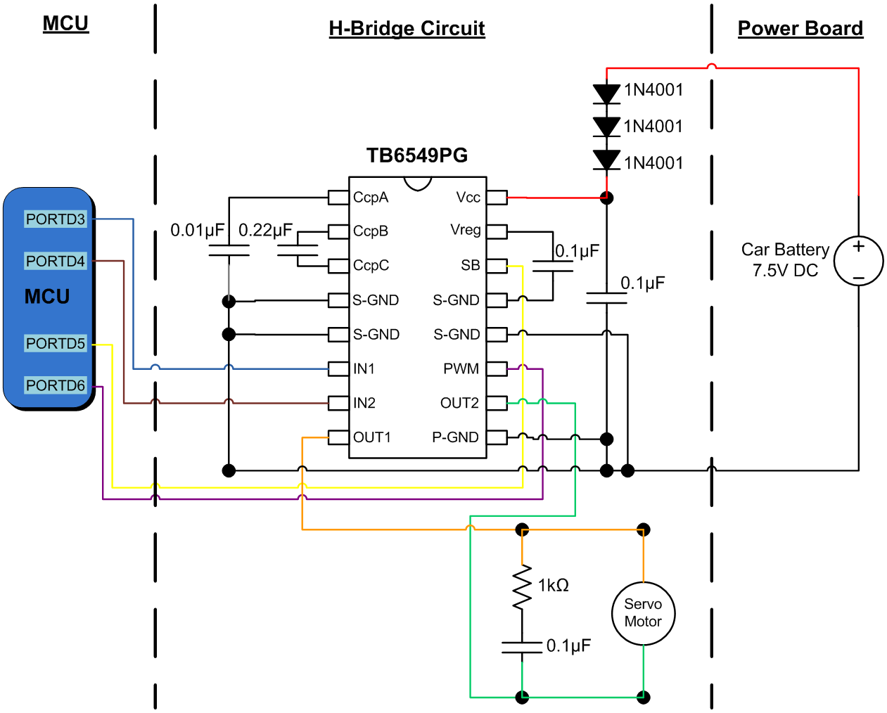
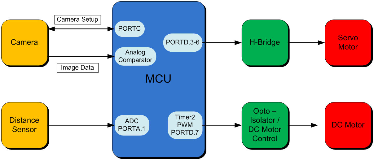
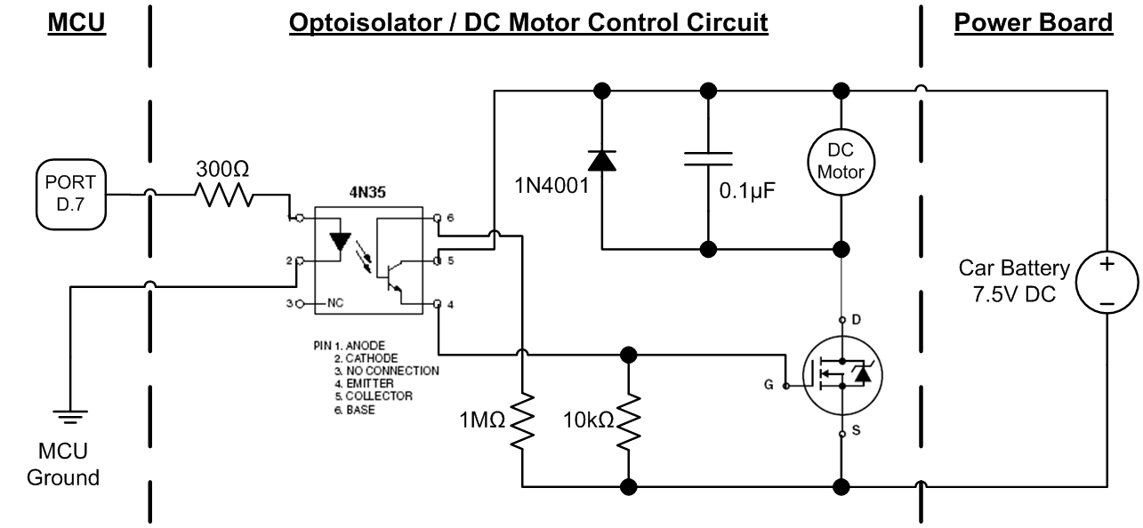
The function turningAlgoSimple() also handles setting up the correct turn signal for the MCU to output to the H-bridge. There are three proper conditions: turn left, turn right, and go straight. The H-bridge has two input ports to control the flow of the current: IN1 and IN2. To turn left, the port pin associated with the IN2 input is set high while the port pin associated with the IN1 input is set low. For right turns, the port pins� values are reversed. To go straight, both pins are set low, meaning no current is sent to the servo motors.
Algorithm tradeoffs
Our current algorithm minimizes the amount of data needed to make a relatively accurate judgement of how to steer the car. This minimization also allows us to greatly reduce the time it takes to receive all the necessary image samples from the camera. Assuming there is a 25 kHz, the camera takes 0.630 seconds to take a 128 by 123 pixel picture, assuming a pixel arrives every cycle. However, if our algorithm only uses lines 20, 40, and 50, we only need to take a 128 by 50 pixel pictures. This will only take 0.256 seconds, which is a 59% speed increase. Since the algorithm code is lightweight, the bottleneck is at camRead(), so this speed increase allows for more samples and a better tracking of the lanes. Also, using less lines means that the picture can be much smaller. However, for more flexibility, we decided to keep picture array as its full size, since it only took about 52% of the 4 kB memory.
In order to make it so lightweight, the algorithm is very specialized, and requires very ideal settings in order to work properly. Our main issue is that we have to assume that the exposure time is adequate for the entire duration of a drive; the algorithm cannot automatically adjust the exposure time of the camera if there is too much noise. This means that we cannot run our car in an environment with too much variation in light without manually configuring every different light scenario first. Timing constraints prevent us from implementing the automatic exposure time adjustment functionality. By the time the camera is properly reconfigured, the car would have most likely driven off a lane due to missed camera samples.
Also, many corner cases are not covered by the algorithm. For instance, we don�t check if the car is currently driving on a lane, of if the car ever drives off the track. Fortunately, the corner cases that are not covered should not arise, assuming the car starts within the track and the track is properly made.
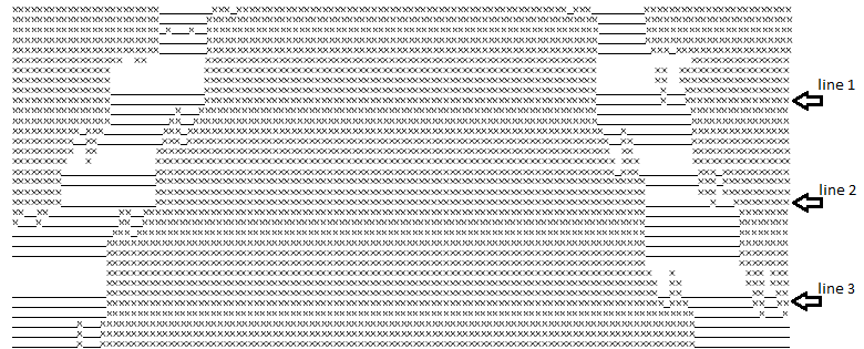
Sample Camera Output and Algorithm Run
Below is an example execution of the algorithm on a pair of straight lanes with line samples at y axis offsets of 10, 20, and 30. The find location methods determine the proper left and right lane positions for line 1, and seeing that there are 2 distinct lanes, the algorithm calculates the proper line center. Comparing this center to the car center, it sees that the difference is within the go straight condition range, so the pins controlling IN1 and IN2 are both set low.
Miscellaneous
Macro explanations
We use the following macros to help simplify our code.
-
cbi(a,b) � Clear bit in a at the bit location denoted by b.
-
sbi(a,b) � Set bit in a at the bit location denoted by b.
-
check(a,b) � 1 if the bit In a at the bit location denoted by b is 1, 0 if it is low.
-
absolute(a,b) � Set a as the absolute value of b.
ISR
Our code uses the Timer 0 compare A interrupt to create the clocks that drive our camera and provide a hardware delay for our ADC distance sensor code. To do this, we create two clocks, XCK and halfXCK, where halfXCK is a phase shifted version of XCK by p/4. To do this, we let each interrupt trigger at a quarter of the total period. In the interrupt, we alternate between toggling the XCK and halfXCK. Doing this, the clocks will stay high for 2 interrupt calls and low for 2 interrupt calls, creating a complete clock period in 4 interrupt calls. Using a 20 MHz with no pre-scalar and OCR0A as 199, we see that the clocks have a frequency of 25 K. To insure that the distance sensor is sampled correctly by the ADC, we implement a counter that tracks the number of XCK cycles. The distance sensor code uses this counter to stall for the correct ADC values, waiting 4 cycles. This is more than enough time.
PuttyTestTask
To help debug our design, we created a simple putty terminal command interface using the UART, called puttyTestTask(). Within the terminal, we had the following commands.
-
p � Take a picture.
-
d � Display the current picture stored in picture[], with �X� denoting 1 and �_� denoting 0.
-
c � Take a picture and run the turning algorithm. Print �turn left�, �turn right�, �go straight�, or
�invalid� depending on what the algorithm returns.
-
a � Adjust the exposure time of the camera by calling the function adjustLighting().
-
t � Display the current lighting settings.
The function puttyTestTask() can only be ran when the car is set to a testing state; The pwm should be turned off and puttyTestTask() should be the only function in the main loop.
Software Issues / Software Design Tradeoffs
-
Distance Sensor Execution Time: The highest priority code of our system is the image processing and alignment algorithm that controls the turning of our car. Thus the distance sensor control code had to be minimized in terms of computation time as much as possible. This resulted in a smaller degree of accuracy when detecting distance. In addition, the reaction time of the system to an object that it is getting closer to is not optimized because computation time is shunted to the image processing control. However, the software goes through all the computations fast enough for the system to detect when to slow down with a reasonable reaction time.
-
Pixel Array Row Selection: For our turning algorithm, to save computation time, only a few rows of the image pixel array are used to calculate whether or not the car should turn. There were many factors to consider when selecting which rows of the pixel array were to be used in the algorithm. The advantage of selecting rows farther down the pixel array is that the image data corresponds to a physical area that is closer to the car and thus would synchronize the turning algorithm�s result with the correct operation of the car. The disadvantage is that more pixels have to be stored on the MCU meaning a larger array and requiring more computation time for the whole turning algorithm. Selecting rows that are higher up in the array have the advantage of saving computation time by requiring a smaller array to store the image data, but have the disadvantage of detecting a physical area that is too far ahead of the car so that its servo motor response is not properly synchronized. Our final design used rows 15, 25, and 35 out of a 128 row array which worked well since the mounted camera angle was large enough that those higher rows in the image array did not correspond to a physical area too far away from the car.
|

 Pg. 9 of Datasheet
 Pg. 9 of Datasheet. Loading one register.
 Pg. 16 of Datasheet. Loading all the registers.
 Pg. 17 of Datasheet
 Pg.14 of datasheet