Introduction
Sound Byte: Real-time vocal pitch shifter on the ATMega644 microcontroller.
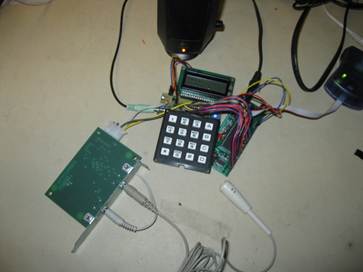
The point of this project was to design and build a real time pitch modulation system where one can sing into a microphone, push a key on a keypad, and hear a shifted version of their voice on a set of speakers. One mode shifts the output to a frequency independent of the input frequency. Another mode outputs the input signal to a constant shifted interval, such as a 3rd, 5th, or octave. Such operations use similar principles to “Auto-tuning”, where the user’s voice is shifted up or down in frequency, but the length of the signal remains the same.
High level design
The use of auto-tuning as well as pitch control and correction is widespread in today’s music industry. There are many professional musical groups that have profited on the use of these concepts. However, most pitch correction programs are applied once the signal has been fully recorded and encoded as a sound file. This final project aimed at producing the same pitch-shifting capabilities in real-time on a microcontroller.
At first, it was thought that the only way to achieve pitch-shifting was to transform the signal into the frequency domain, then apply a frequency-domain pitch-shifting algorithm, and transform back to the time domain. After further research, however, an algorithm called Time Domain Harmonic Scaling (TDHS) was discovered. TDHS uses the Pitch-Synchronous Overlap Add (PSOLA) method to scale pitch in the time domain. A modified version of this algorithm was what was finally implemented in the final project’s design. The following block diagram shows the final high level design of our pitch-shifter:
Figure 1 : High Level Block Diagram of Pitch Shifting Project
The microphone used in this project was a standard passive microphone with a 3.5mm jack. This microphone required a separate board to boost the signal to a +/-2.5 V signal. Additionally a standard set of 3.5mm input jack speakers operating at +/-2.5 V were also used to output the pitch-shifted signal.
One main trade-off was the use of hardware filters as opposed to digital filters. The decision to use hardware filters was easy to make since using hardware filters takes load off of the microcontroller. The downside to using the hardware filters is that they have slower gain drop off at the cut-off frequencies as compared to digital filters. However, this did not affect our sound quality significantly and was therefore deemed an acceptable trade-off.
It should be noted that the idea for the pitch shifting project was partially influenced from the success of the trademarked Antares Audio Technologies Auto-tune product. This final project’s goal was to produce a similar product that also shifts pitch, using much less hardware for a fraction of the price of a product such as Auto-tune.
Hardware Design
Input Hardware:
The first component of the pitch shifting project is a standard passive computer microphone, which is used to receive a vocal audio signal. This signal is then passed through an amplifier to boost the signal’s amplitude from fractions of a volt to +/-2.5 V. This amplifier requires a +5V power supply and simply takes an input passive microphone and boosts the voltage. The output from this amplifier is sent through a voltage level shifter to bring the voltage from +/-2.5 volts to 0 to 5 volts. This is necessary so that the ADC converter on board the microcontroller can properly measure the signal.
Next the signal is sent through and a low pass filter. The low pass filter functions to cut out unnecessary high frequency components from the signal. The filter is designed to have a cutoff frequency of approximately 2 kHz, since the highest frequency signals expected on the microphone are band-limited to 1 kHz. Finally, the signal is sampled by the ADC on the microcontroller at a rate of 8 kHz. Note that the microcontroller samples the signal at a much higher rate than the highest expected sound in the system in order to gain better resolution of the signal for later processing.
A 16 button keypad is used to adjust the desired output pitch. By pressing one of these buttons, the user tells the microcontroller how it should scale the input frequency. This keypad is wired up to a port on the microcontroller and communicates using simple logic highs and lows to denote which button has been pressed.
Output Hardware:
After the microcontroller has done the pitch shifting operation on the signal (as explained in the Program Details section), the signal is output using the fast pulse-width modulation (PWM) mode on the microcontroller. This digital output is then sent though a low pass filter in order to average it into an analog waveform. Next the signal is then sent through another level shifter which is tasked with bringing the signal’s voltage from 0 to 5 volts back to the +/-2.5 volts necessary to interface with the speakers. Finally, the signal is output to a speaker.
As an auxiliary feature, an LCD display is used to show the user’s current pitch and the desired pitch. This display is updated at a rather slow rate of once per second so that the LCD print statements interfere minimally with the primary functionality of the pitch shifter.
Software
Interrupt Service Routine (ISR)
The Interrupt Service Routine is responsible for the sampling of the signal. Timer 2 is used to trigger the ISR every 125 µs which corresponds to a sampling rate of 8 kHz. Upon execution of the ISR, the value from the ADC gets read into an integer array (also referred to as a buffer) of length WINDOW_SIZE, which is a compiler definition that is normally set to 128. Note that the size of this array is picked to be long enough so that the processor has enough data to do a pitch shifting operation, but also short enough so that the microcontroller doesn’t run out of memory or computation cycles. After the data from the ADC has been read into the input array, the PWM output register gets set to the value stored in an output array.
An array buffer system of four arrays is used so that the microcontroller can pitch shift in real time. At all times, one array is used to store data from the ADC, one array is used to output data to the PWM, and the other two arrays are used for the actual pitch shifting operations. Once an array has been fully written to (which occurs at the same instant that an array has been fully read out of), all of the arrays switch (the read-in array becomes an operation array, the second operation array becomes the new output array, and the output array becomes the new read-in array. The arrays switch depending on the status of a control variable called arrayFlag that stores each array’s current functionality. The following table shows this buffer system:
|
Value of arrayFlag |
Role of array1 |
Role of array2 |
Role of array3 |
Role of array4 |
|
1 |
Input |
Output |
Receives resampled data |
Source of resampled data |
|
2 |
Source of resampled data |
Input |
Output |
Receives resampled data |
|
3 |
Receives resampled data |
Source of resampled data |
Input |
Output |
|
4 |
Output |
Receives resampled data |
Source of resampled data |
Input |
Table 1 : Breakdown of Array Buffer system
Function: main()
The function main() first calls the initialize function initialize() to set up the ISR and initialize variables. Next, main() enters an infinite loop, where it waits the ISR to switch buffer arrays by waiting for the arrayFlag to change value. Once arrayFlag changes value, the main computational functions are called that operate upon the current operation array. These functions are calcf0(), which calculates the signal’s fundamental frequency (necessary for the pitch shifting operation); keyPad(), which probes the attached keypad for user input; calcDesFreq(), which determines which frequency to switch depending on the program’s current state and what keypad value has been selected; and resample(), which does that actual pitch shifting operation.
Function: initialize()
The initialize() function sets up the port directions and initial values. Port A gets set as an input for the ADC to sample the input signal on pin A.0. Port B gets set as an output so that the PWM can output the pitch shifted signal on pin B.3. The ADC is initialized with a prescaler of 64 and a compare register set to 39 ticks so that the ISR operates at approximately 8 kHz. The LCD is also initialized and text is written to it that will not change for the remainder of the function. Finally the ISR is set up and enabled.
Function: calcf0()
The function calcf0() calculates the fundamental period of the input signal. Since the input has been sampled and separated into arrays, the function can only calculate the fundamental period of the current array. This is done by calculating the correlation of the current array with itself at multiple offsets. Whichever offset gives maximal value corresponds to the fundamental period. Note that an offset of zero would give the highest correlation (equaling to the signal’s autocorrelation), but this value is meaningless and thus its value is not checked. In fact, the smallest offset that is checked is an offset of 8, which corresponds to a fundamental frequency of 1000 Hz, which is the upper bound of the system.
The first step in this fundamental period calculation is to check the arrayFlag to determine which array’s information should be used to compute the fundamental period. This is done by using an if / else if statement on arrayFlag. Within the if statement, a nested for loop is entered. The outer loop loops over a range of correlation offsets (8 to 40). The inner loop computes the correlation at this offset. This is done by multiplying the array’s value at index k by the array’s value at index (k - offset) and summing over all k. When the offset corresponds to 1 period, the sum will be larger than any other offset in the range. Once the inner loop exits, an if statement is used to keep track of the maximum value. The period is stored once the maximum has been found. The frequency corresponding to this period is trivially calculated as the sample rate divided by the period.
Function: keyPad()
This function is responsible for determining which button has been pressed on the keypad. This is done by setting 4 of the pins of port C as outputs and the other 4 as inputs and reading the values on the input pins. Then the pins that were outputs are switched to inputs and vice-versa, and the new input pins are read. A variable is saved that stores all of the values pulled from the input pins and this is searched against a look up table called keytbl. If the variable value is found, then a variable named butnum gets the appropriate number, corresponding to a unique keypad button. If the code is not found, butnum gets set to 0. This process determines which button was pressed and ensures that only one button was pressed.
Function: calcDesFreq()
The function calcDesFreq() is responsible for determining which frequency the pitch shifting algorithm should shift the input signal to. If the keypad is not being pressed (in which case the variable butnum takes a value of 0), the output frequency is left unchanged. When a button is pressed, the desired pitch is set to a value which is determined from a predefined array within the program. Note that this pitch is independent of the input pitch. This array is configured so that each incremental button press approximately corresponds to a pitch in the C major scale. Note that in order to actually change the pitch, a variable named scale is set and used later in the resample() function. This variable essentially corresponds to how much the signal gets up or down sampled by. If scale takes a value of 1, the signal is not scaled at all.
Another mode is offered that outputs the input signal at a shifted interval. This mode is entered if the bottom right button (the D button) on the keypad is held down, and any other button is pressed. The second button that is held down corresponds to one of the 12 chromatic intervals from the fundamental frequency that is being sung into the microphone. Therefore using this mode, the pitch shifter can effectively harmonize with its singer at any interval.
Function: resample()
The resample function is responsible for the actual pitch shifting operation. Like calcf0, this function first tests the value of arrayFlag to determine which buffer array to read and write from. Next, a for loop is entered that is designed to loop over each element of the output array and calculate its value.
For the first element of the output array, the program attempts to match the phase of the last element of the last output array to the first element of this new output array. If this was not done, the output signal would have transients that would result in poor output sound quality. This phase matching is accomplished by looping over the first period of the current input array and finding the slope and the amplitude for each point. This slope and amplitude is then compared to the previous output array’s slope and amplitude, and if there is a match, the index for that point in the input array is saved in a variable called start. The first element of the output array is then set to the value of the input array at the index of the value of the variable start.
After the first element of the output array is set, each additional element is then set to the value of one of the elements of the input array. The element of the input array that is selected starts at the index previously calculated (so the phase of the output arrays align) and is incremented based on a scale factor previously calculated based on the desired and current frequency. This process essentially acts to resample the data in the input array into an output array at the resample rate given by scale. Note that if the resample rate is greater than 1 (meaning that the pitch will be increasing) the input array will run out of data to save into the output array. To resolve this problem, the program will loop back to the beginning of the input array. The program will then attempt to match the phase of the beginning of the input array to the last data saved into the output array in a similar manner to how the phase was matched previously. This process again aims to reduce the number of transients in the output signal.
Things tried that did not make it into the final design:
Originally we aimed at using an autocorrelation method to determine the pitch being input into the microphone. This method's advantage is that it does not require a pure sine wave to find a fundamental frequency. However this method lacks accuracy. In order to increase the accuracy of the pitch detection, a system that detects a when pure (or mostly pure) sine wave crosses zero was implemented. This system, called the zero-crossing method, proved to find the pitch of a signal only slightly more accurately and was not as robust as the autocorrelation method. In the end, the autocorrelation method was used to find pitch. Given more time to work on the project, a combination of the two methods might have proven to given the best results.
The actual process of pitch shifting is a complicated problem, and many methods were considered to solve it. Originally, a Fast Fourier Transform (FFT) was to be used on the input signal. The result would then be pitch shifted, and an inverse FFT would be used to get the signal back into the time domain. This method would have involved a great deal of computation and would not have made the pitch shifting operation any easier.
The next method that was considered was using Hanning windows to separate the input data into segments. These segments would then be shifted closer together or farther apart depending on the desired direction of pitch shifting. This process shifts the pitch without requiring a transform, therefore requiring much less computation. The idea to use Hanning windows and a demonstration of the method was given by Josh Patton from his web site (cited below). After trying this method, the addition of multiple input arrays proved to make the Hanning window operation too complex of a solution on the microcontroller. However the idea of the Hanning windows was then used to come up with the final solution of resampling and cycling the data. This proved to be far less complicated and faster than the two previous methods.
Results
The project works in real time with only 16ms of lag, which is virtually unperceivable to the user. This small lag is caused by the use of the circular buffer used to save the sampled data in arrays. A more noticeable problem is that there exist occasional transients in the sound waveform that negatively affect the output sound quality. These transients are most likely a result of the resampling operation not properly aligning the last part of the waveform from previous array with the first part of the waveform from the next array. The act of sampling at 8 kHz also degrades the sound quality slightly, giving the output a sort of tinny, telephone like sound. This sampling rate was very much a limiting factor from the microcontroller, and could have been increased with the addition of multiple microcontrollers in parallel.
The project is very easy to interact with, given its simple nature. The user only needs to sing into a microphone and operate the keypad in order to manipulate his/her voice’s pitch. In addition, the user can see on the LCD the pitch he/she is singing at a given moment in time and in addition, read off the pitch the microcontroller is attempting to correct to on the speakers.
The
pitch detection scheme that was implemented is accurate to within about 25 Hz.
At lower frequencies, this corresponds to about a musical half step.
At higher frequencies, this inaccuracy is less significant. This
relative inaccuracy at determining pitch has some negative effects upon the
accuracy of pitch shifting since the fundamental frequency is required for the
pitch shifting operation.
Below are screen shots taken from the FFT on the oscilloscope of an original signal at 245hz and a pitch shifted signal at 345hz. The desired frequency for this pitch shift was 349hz and the total error was therefore 1.16%. Additional measurements of pitch shifted signals and their error are shown in a table below.
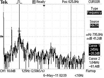
Figure
2: Original (un-shifted) Signal
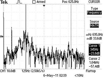
Figure
3: Pitch Shifted Signal
|
Calculated Freq |
Desired Shifted Freq |
Measured Scope Freq |
Error |
|
258 |
258 |
245 |
5.31% |
|
258 |
349 |
345 |
1.16% |
|
258 |
523 |
510 |
2.55% |
|
258 |
784 |
750 |
4.53% |
|
258 |
1047 |
1020 |
2.65% |
|
501 |
501 |
495 |
1.21% |
|
501 |
349 |
345 |
1.16% |
|
501 |
523 |
510 |
2.55% |
|
501 |
784 |
750 |
4.53% |
|
501 |
1047 |
1000 |
4.70% |
|
Average Percent Error: |
3.03% |
Table
2: Accuracy of Pitch Shifting
Safety Concerns:
All voltages within the project are kept within 0 to 5 volts, a very safe operating range for humans. Furthermore, the voltage regulator acts as a temporary current limiter to insure that a short across the power supply would not result in a large discharge. Such a short could potently start a fire if the regulator is near flammable substance, and for that reason, among others, shorting the power supply was avoided.
There was no interference with other groups other than the potentially distracting noises produced while testing the product. Anyone that can produce an audible vocal tone can use the project. Furthermore the keypad and microphone interface is quite straight-forward.
Conclusions
Overall, the vocal pitch-shifter worked mostly as expected. The sound quality observed is not wonderful but the product still serves as a proof of concept. The somewhat poor sound quality of the output mainly stemmed from the limited processing power of the microcontroller. Since the maximum feasible sampling rate was 8 kHz, our pitch detection algorithm had limited precision. All of the other flaws in the design followed from this. If the project was to be redone, it would be beneficial to investigate the use of additional microcontrollers in an attempt to speed up the sampling rate an increase the sound quality.
Other Notes
The input microphone circuitry was set up to be able to interface with virtually any standard 3.5mm jack. Likewise, the output circuit was designed to interface with a standard set of 3.5mm jack speakers operating at +/- 2.5 V.
Before deciding upon a viable pitch-shifting algorithm, much research on the web was conducted. Factors such as sound quality, computational efficiency and feasibility, and complexity were considered. While all of our code was original, inspiration was drawn from other sources. One such source was the Matlab pitch-shifting and time-scaling project of Josh Patton. A link to his work is provided in the references section below. No code from the public domain was used in the creation of this project.
In a sense, a design was reverse-engineered since the final goal was in mind when the projected started that had already been accomplished on a more sophisticated system. However, a pitch shifter has most likely never been done on an 8-bit 20MHz microcontroller before now. No sample parts were used in the construction of the project and therefore no non-disclosure agreements were signed.
If the system could have been made more robust with better quality sound, there would be potential for a patent or publishing opportunity. We do not know of any legal considerations that our product could have violated.
In developing our product, the IEEE Code of Ethics was fully maintained. At no point did we believe that there would be any safety concerns with our product. If this had been the case, we would have sought to make the necessary precautions regarding this. At all times, we strove to improve our understanding of the technology and algorithms needed to complete this project. When we did not understand something, we conducted the necessary research on the web until we were able to solve the problem. In addition, we also asked others for advice on certain problems that were difficult to solve. Several times during our work on the project we sought guidance and constructive criticism from others in an effort to deliver the best quality product given the time constraints. We were honest and realistic with ourselves when determining which tasks to devote our time to. At all times in the lab, we were courteous and helpful to others. We provided support to others when they needed it and did our best to ensure that we did not interfere with their work. Above all, we made sure that no work was plagiarized and we cited references whenever other work was used for inspiration.
Circuit Schematics
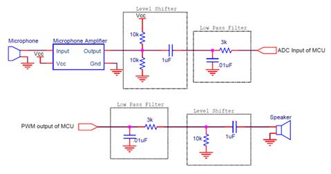
Figure 4 : Low Level Diagram of Input and Output Circuits
Budget Details:
|
Part |
Acquired From |
Quantity |
Each ($) |
Total ($) |
|
Protoboard |
ECE 4760 Lab |
1 |
4.00 |
4.00 |
|
Atxmega644 |
ECE 4760 Lab |
1 |
8.00 |
8.00 |
|
Header Pins |
ECE 4760 Lab |
36 |
0.05 |
1.80 |
|
Microphone |
Home |
1 |
0.00 |
0.00 |
|
Microphone Amplifier |
Home |
1 |
0.00 |
0.00 |
|
LCD |
ECE 4760 Lab |
1 |
8.00 |
8.00 |
|
Keypad |
ECE 4760 Lab |
1 |
6.00 |
6.00 |
|
Speakers |
ECE 4760 Lab |
1 |
0.00 |
0.00 |
|
Resistors |
ECE 4760 Lab |
5 |
0.00 |
0.00 |
|
Capacitors |
ECE 4760 Lab |
4 |
0.00 |
0.00 |
|
Total: |
27.80 |
Breakdown of Workload:
Throughout the five weeks we worked on this project, we totaled approximately 175 man-hours. Here is a list of the main tasks that comprised this project:
Conceptual Work - Joe, Evan
Hardware Design
· Voltage Level up shifter - Evan
· Low pass filter for input - Joe
· Low pass averager for output - Joe
· Voltage level down shifter - Evan
Hardware Fabrication
· Target board soldering - Joe
· Circuit board soldering - Evan
Software Design and development
· Code programming - Joe, Evan
· Testing - Joe, Evan
· Debugging - Joe, Evan
Lab Report
· Writing - Joe, Evan
· Revising - Joe, Evan
· Editing - Joe, Evan
References
ATMega644 datasheet.
James Respaut at Phillips for the microphone amplifier.
Patton, Josh. “Pitch Synchronous Overlap and Add (with Formant Preservation)” <http://www.ece.uvic.ca/~jpatton/yeshua1984/Elec484/Elec484.html> Aug 10, 2007.
Houser, Graham. Jeans, Alysha. Soundar, Sam. Szalkowski, Matt. “Speak and Sing - Pitch Correction with PSOLA” Connexions. Dec 20, 2009. <http://cnx.org/content/m33242/latest/>
Bernsee, Stephan. “Time Stretching And Pitch
Shifting of Audio Signals – An Overview” The DSP Dimension. Aug 18, 1999.
http://www.dspdimension.com/admin/time-pitch-overview/
Code