"a human tracking rotating platform that supports a fan"
project soundbyte
For our final project we decided to construct a human tracking rotating platform that supports a fan.
The platform, using dual element Pyroelectric Infrared Sensors (PIR) sensors, rotates itself independently to direct air flow to whatever position a person moves to. In addition, the fan includes another setting that allows precise rotation between two people. These modes are selectable by the user. The running mode is displayed on an LCD.
We decided to pursue this project because we had become fed up with the common fan’s limitations.
High Level Design
Rationale and sources of the project idea:
Although we experience cold weather for much of the Fall and Spring semesters when at Cornell, we have both lived in regions where the temperature and humidity is very high. In addition, neither of us had air conditioning. Using a fan was the standard way of cooling down and still is for many people. Unfortunately fans do not have very efficient or useful features when it is desirable to change the direction of air flow. Fans usually provide two options for directing airflow:
1. The fan is static and needs to be physically redirected to direct air in the desired direction.
2. The fan can rotate back and forth at a set angle which is approximately 180 degrees.
The first option is quite inconvenient when one wants to change their location in the room and thus redirect the fan’s air flow. It requires physical effort which may be difficult if the fan is large or the user is of elderly age. In addition it may require multiple attempts before actually getting the fan to redirect air flow in the exact desired direction. The second option is wasteful as the fan may direct air at empty spaces for much of the rotation cycle. Thus, we decided to focus on a project that could solve the daily stresses and inconveniences of fan use by automating the process.
Logical Structure:
Our solution to this problem consists of two dual element PIR sensors directed in the same direction as the fan. They can be seen in Figure 1 below. The PIR sensors measure infra-red light that is radiated in their field of view. They each contain two internal compensating pyro electric windows, one positive and the other negative, to minimize disruption from sources such as temperature variation. We decided to block the negative side with tape to increase the sensors sensitivity. Because humans typically radiate more infra-red light than their surroundings, such as a wall for instance, detecting motion is fairly simple.
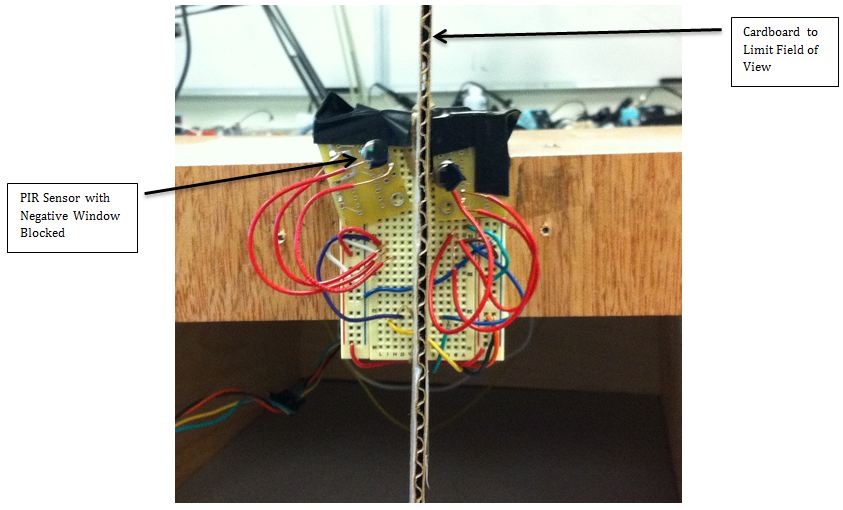
Figure 1: PIR sensors
The two PIR sensors are separated in the middle. The purpose of this is to separate the sensors’ field of view.
When a sensor detects the right amount of infra-red light a comparator output goes high. We use the microcontroller to generate an interrupt on the comparator’s rising edge. The interrupt then signals a task that begins rotating the platform’s motor. The rotation is clockwise if the left sensor has detected a person or counter clockwise if the right sensor has detected a person. Once the fan is directed at the person’s location, there is just enough infra-red light in the second sensor’s field of view to trigger its comparator. This generates an interrupt that signals a task to either stop or redirect the motor, depending on the setting. At this point the customer is nice and cool without any effort from their side.
An example of the fan’s operation is illustrated in the block diagram below.
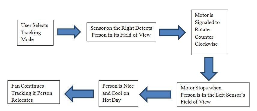
High-level block diagram
Hardware
1. The Rotating Platform:
The rotating platform can be seen in Figure 2. The platform is mounted on four standoffs. The standoffs are mounted on a lazy Susan. We placed an O-ring around the standoffs and the motor shaft to increase the gear ratio, slow down the platform rotating speed, and produce more torque.
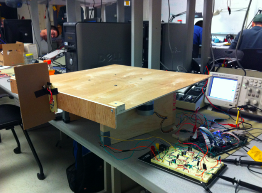
Figure 2a: Rotating Platform
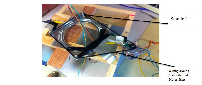
Figure 2b: Underneath the Platform
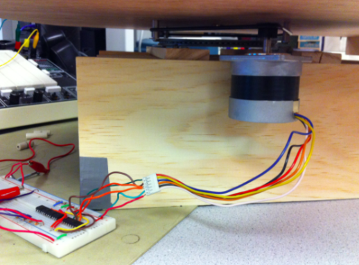
Figure 2c: Sideview of Platform
2. The Stepper Motor:
Motors need to be isolated from the AVR. This is because they produce a high voltage spike when the current flow through them suddenly changes. This can damage the digital circuitry in the microcontroller. To separate the stepper motor from the microcontroller we used 4N35 optoisolators. Furthermore, ULN2003 drivers are used to supply the high current needs of the motor since the microcontroller has a maximum current rating of 40mA. The drivers contain diodes to protect the circuitry from high voltage spikes by directing the current through the power supply.
The motor is controlled using an 8-step sequence to halve the rated step angle. The step sequence rate is controlled via software. The 8 step sequence not only slows down the motor but also allows more accurate positioning of the platform.
3. The Pyroelectric Infrared Sensor Circuits
A standard circuit application was used to detect a person. The schematic can be seen below. It was modified to serve our project purposes. The PIR sensor can be modeled as a BJT. When the device is triggered current flows through the BJT and a signal voltage proportional to the amount of current is produced. The circuit biases the sensor output and integrates it. The output of the integrator is fed into the comparator which we adjusted to obtain the best sensitivity we thought made the system operate best. When the output is greater than the threshold the output goes from low to high.
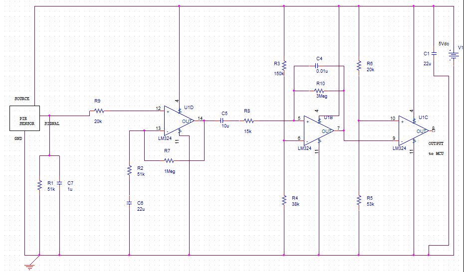
PIR Circuit
Upon detection, the output of the comparator remains high for as much as 2.5 seconds. This degrades system performance for reasons that are explained later. To fix this we increased the comparator threshold as well as decreased the feedback resistor on the integrator. Although both solutions improved the response of the circuit these solutions decreased the sensor’s range. Thus, we decided to minimize these changes as much as possible.
4. Limit Sensors
To avoid hazardous situations such as tangled wires the fan was allowed to rotate at angles that were no greater than 180 degrees. Two metal strips, one on each side of the fan, were grounded. Another strip of metal was mounted on the lazy Susan at the front center of the platform. The lazy Susan was connected to a pin on the development board with an activated pull up resistor. When the strips of metal touched, the pin was set low and detected by the microcontroller. The software was set to check the sensor every 50 msec. The sensors can be seen in Figure 3.
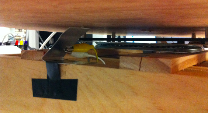
Figure 3a: Limit Sensors
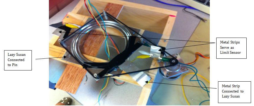
Figure 3b: Limit Sensors
Software
Program Details:
Our program was written using the multi-tasking kernel Tiny Real Time which was first introduced in our 4th lab. The link to this API is available in the Appendix. The code was written in C and ran on the ATMega 644 microcontroller from ATMEL. The code is available for viewing in the Commented Code section.
1. Stepper Motor Control
We decided to use a half-step 8 step sequence to operate our stepper motor. Each of the eight steps was saved in a structure that contained a different step output for the motor. In addition each structure contained two pointers. One for the structure containing the next step in the sequence and the other for a structure containing the previous step in the sequence. Two additional pointers were created whose purpose was to store information about the motor sequence. When the motor spun counter clockwise the pointer forwardPtr pointed to the current step, while the pointer reversePtr pointed to the previous step. When the motor spun clockwise the pointer reversePtr pointed to the current step and the pointer forwardPtr pointed to the previous step in the sequence.
The rate of the stepping sequence was set up using a timer overflow interrupt. A pre-scalar of 256 on a clock rate of 16MHz was sufficient to keep rotation at an acceptable rate. Not too slow to avoid a large waiting time and not fast to minimize detection misses.
The global variable motorDirection is always set, using code definitions, to the motor’s immediate state. This is either clockwise, counter clockwise, or stopped.
2. External Interrupts on Sensors
As discussed previously, upon detection of movement, the PIR circuit output for each sensor goes high. We used the microcontroller’s external interrupt capabilities to generate an interrupt upon detection of a rising edge on its pins. Each external interrupt service routine signals a task that handled the system control according to the user’s desired setting.
3. Task 1
When the single human tracking setting is on, this task is signaled when an external interrupt on pin int0 is detected. This pin is connected to the sensor on the right. If the task was signaled at a time that the platform was stationary, or in other words when the variable motorDirection was equal to stop, the task sets the variable motorDirection to counter clockwise. Later this new information will be used by the timer to rotate the motor in the proper direction.
On the other hand, the task may have been signaled by the sensor on the right while the motor was rotating clockwise. In that case the task sets the variable motorDirection to stop since this indicates that the fan has reached its destination.
4. Task 2
When the single human tracking setting is on, this task is signaled when an external interrupt on pin int1 is detected. This pin is connected to the sensor on the left. If the task was signaled at a time that the platform was stationary, or in other words when the variable motorDirection was equal to stop, the task sets the variable motorDirection to clockwise. This information will be used by the timer to rotate the motor in the proper direction.
On the other hand, the task may have been signaled by the sensor on the left while the motor was rotating counter clockwise. In that case the task sets the variable motorDirection to stop since the fan has supposedly reached its destination.
5. Task 3
When the operational mode is set to rotate between two people, and an interrupt on pin int0 occurs, this task is signaled to operate. If the motor was stationary before the task was signaled, this task sets the global variable motorDirection to counter clockwise. On the other hand, if the motor was rotating clockwise then the motor is stopped to direct air flow at a person for half a second and then begins rotating counter clockwise toward the second person.
6. Task 4
This task is the dual of Task 3. When the operational mode is set to rotate between two people, and an interrupt on pin int1 occurs, this task is signaled to operate. If the motor was stationary before the task was signaled, this task sets the global variable motorDirection to clockwise. On the other hand, if the motor was rotating counter clockwise then the motor is stopped to direct air flow at a person for half a second and then begins rotating clockwise toward the second person.
7. Task 5
This task is a debouncer for the push button on the development board. It operates periodically every 50 msec. The task begins by reading the value of the push-button, which is active low. If the debouncer does in fact detect that a button was pushed it toggles the fan setting between 3 modes. These modes are: OFF, Tracking Mode, and 2 Person Mode. The running mode is displayed on an LCD. Switching between modes re-initializes all major parameters to their default values and the variable motorDirection is set to stop. Once this is done, and the button is released, the debouncer waits for a new input again.
8. Task 6
This task makes sure that the fan can only rotate at an angle of 180 degrees to avoid an unsafe situation such as tangled wires. When either of two limit sensors, placed to limit the fan’s motion to 180 degrees is activated, a pin on the development board is set low. This pin is tested by the task every 50 msec. If it detects that the pin is low, the task will redirect the fan’s direction of rotation. Thus, if the fan was rotating clockwise, and a sensor is activated, the fan will immediately begin rotation counter clockwise. Similarly, the fan will immediately begin rotating clockwise if it was rotating counter clockwise and the sensor was activated. This also allows the fan to track the person again if they were not detected previously.
9. Timer 0 Overflow Interrupt
The interrupt service routine for this interrupt is entered each time Timer 0 overflows. The operations in the interrupt service routine depend on the value of the variable motorDirection upon its activation. If the variable motorDirection was equal to stop, no operation will occur. The motor remains static. If upon entrance into the ISR the value of the variable motorDirection was equal to counter clockwise, PORTA of the development board is set to a motor step to drive the motor. Then, the pointer forwardPtr is set to point to the structure with the next step in the sequence while the pointer reversePtr is set to point to the structure of the current motor step. This is done to maintain consistency in the motor’s steps if the motor needs to suddenly redirect its direction of rotation.
If the value of the variable motorDirection was set to clockwise, PORTA of the development board is set to a motor step to drive the motor. Then, the pointer reversePtr is set to point to the structure with the next step in the sequence while the pointer forwardPtr is set to point to the structure of the current motor step.
Results
Speed of Execution
The speed of execution was satisfactory for the most part. Upon detection of a human the sensing circuit responds immediately, causing the circuit output to go high. This low to high transition is captured by the microcontroller and system operation begins. Unfortunately, once the sensor does detect a human, its output may remain level for as much as 2.5 seconds. The system cannot respond until the sensor output settles since a rising edge is required to trigger a new response from the system. We attempted to solve this problem in multiple ways, but these changes resulted in the degradation of the circuit’s sensing distance and sensitivity. Our attempts to solve the problem included increasing the comparator’s voltage threshold as well as decreasing the integrator’s feedback resistance to quickly discharge the capacitor.
Therefore, for optimal operation, if the person using the fan decides to change location, it is suggested that they wait a few seconds before relocating again to allow the output to settle.
One rotation is approximately 19 seconds. This is sufficient to lag a little behind quickly moving people but the fan stops once it reaches its correct destination.
Accuracy
The fan usually stops directly or nearly in front of the person, as desired. In addition, the sensing distance is quite good and can be up to 3 meters. The field of view for the sensors used, D203B PIR, is shown in Figure 4. Since we covered half the sensor’s window to increase the sensor’s sensitivity we also halved its field of view. Thus, motion outside this field of view will most likely not be detected.
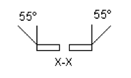
Figure 4: PIR sensor Field of View
Although the sensors almost always detect humans, other sources of heat, especially in the lab, will occasionally trigger the sensors as well. The main sources are electrical equipment in the lab closely situated by the PIR sensors.
Safety
Instead of working directly with a commercial fan, we built a separate platform that can have a fan placed on top of a platform. To avoid tangling wires the fan is permitted to rotate at angle that is no greater than 180 degrees. Except for the fan, all hardware parts in our design can be run with 5V dc.
Interference
Our project did not interfere with other designs as far as we know. However, since our usual testing environment was in a lab full with people, computers, monitors, and oscilloscopes, we did suffer some confusion as to which sources of heat were triggering the sensors. When we tested our design in a separate room, the performance was much more predictable.
Usability
The system is very easy to use. Pressing a switch toggles the operational setting between OFF, Single Tracking Mode, and 2 Person Mode. The system should be used under the right circumstances, meaning anything battery powered can easily be used by simply placing it on the platform. Caution should be observed when using a fan connected to the power lines. There is some risk of wires being tangled together or pulled. Although we account for this using limit sensors we highly recommend caution.
Conclusions
Final design analysis
The results of the project were satisfactory. The platform rotates and stops properly most of the time. Unfortunately, there were some issues with the sensors that were difficult to handle. Mainly, the sensor output is high for a very long time, thus delaying the response of the system. We spent much of our time attempting to change certain circuit parameters to achieve an optimal circuit performance. Looking back, it would have been more productive spending much of that time on coming up with software solutions. Once we realized this we in fact managed to solve many problems using software.
Applicable Standards
We used a standard PIR motion detection circuit which we adjusted for our purposes. In addition, we used LCD libraries which are available on the ECE 4760 web site.
Intellectual Property
Our code uses a real time kernel, called Tiny Real Time, to run processes. The kernel API was introduced in class for our 4th lab. : ECE 4760 TRT Reference
The circuit is heavily based on the circuit provided in the datasheet for the D203B sensor : D203B Datasheet
Ethical Considerations
We do our best to comply with the IEEE code of ethics. Because our project includes the use of a high voltage fan, at all times, testing with a fan was done while both members were present. This was necessary to stop wires from possibly tangling together.
Our project idea and design is our own. We do our best to provide accurate documentation of all aspects of the project and the results in this report. We have posted material that we believe is important, useful, and informative to the readers.
Our platform was constructed from wood and thus required use of sharp tools. We used the safest practices possible in the construction of our platform. We received professional training before using automatic saws. We recommend that those who work with wood wear safety glasses, act cautiously, and adhere to safety standards.
The purpose of our project was to improve an existing technology for the benefit of those that use fans regularly. The purpose of this report is to share the information we have obtained from our experimentation and testing.
Legal Considerations
As far as we know there are no legal restrictions on our project. The project hardware did not include any transmitter and as far as we know does not interfere with the operation of other electrical equipment.
Appendices
A. Commented Code
- final_project_trt.c
- lcd_lib.c (source file) – lcd code from Bruce Land
- trtkernel644.c (source file) – trt code from Bruce Land
- lcd_lib.h (header file) – lcd code from Bruce Land
- trtSetting.h (header file) – trt code from Bruce Land
B. Schematics
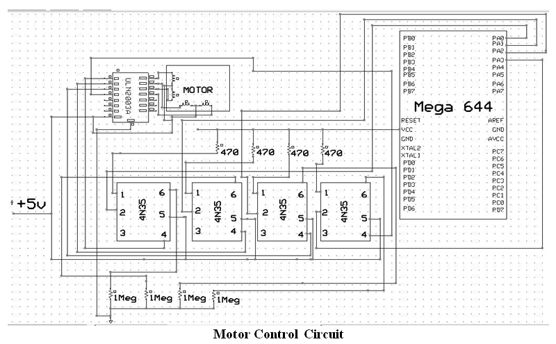
Motor Control Circuit
PIR Circuit
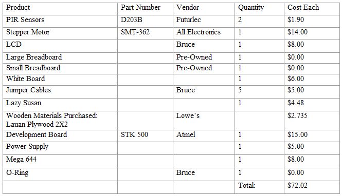
C. Budget Considerations
D. Task Division
- Rotating Platform/Limit Sensors: Joe
- Code: Joe
- Circuit Design: Joe, Emmeline
- Testing/Debugging: Joe, Emmeline
- Report: Joe, Emmeline
- Web page: Emmeline