Our project was to create a new type of controller for a remote controlled helicopter. This new controller is in the shape of a hand paddle that a user can move around to control the movements of the helicopter.
We modified the existing controller for the helicopter and created our own interface for it to digitally control its movements. We modified the helicopter itself to send out infrared signals that allow the paddle to sense where it is in a 3-D space. We thought that toy helicopters were already a cool idea for kids to play with and thought that modifying the controller design to be one similar to the new human controlled controllers such as Kinect and the Wii remotes would be even more interesting to use. In addition to this, if the software logic was good enough to control the helicopter with precision then the helicopter would be easier to control with paddle than with a remote control joystick.
Rational
Our project concept started when we were viewing past years projects and came across the helicopter controlled with a glove. The creators of the project have been referenced in our appendix. We thought it was a really interesting idea to be able to control a helicopter with a different interface than the provided hand joystick controller. We thought that we could expand the concept and create an interactive experience similar to the Kinect or Wii remote. All that was left was the task of figuring out how to actually build the controller. This concept we got from the Digital Tachometer lab, which was using LEDs and phototransistors as our sensors. After that, we started building the Automated Paddle-Controlled Helicopter!
Background Math
Time Constant for Horizontal PWM Control:
Time Constant for Vertical PWM Control:
Hardware/Software Tradeoffs
The only main tradeoff we faced was the responsiveness of the control versus the stability of the helicopter flight. If the helicopter was to correct itself instantly at high speeds, there was a fair chance that it would exceed the range of the paddle and start flying blind. If we made the speed and accuracy of the correction algorithm very slow, then the responsiveness would suffer and the helicopter may not be controlled very well. We decided to pick a range of speeds that maximized both qualities of our design.
Program Details
Introduction
In order to control the throttle and heading of the helicopter, we used four Infrared Sensors spaced in a grid-like fashion and an Infrared Emitter on the face of the helicopter. The program converted these four analog inputs into digital variables. We use these measurements in conjunction with a PID feedback algorithm to control a pulse width modulated signal. The PWM is then low-pass filtered back to an analog signal that would control our potentiometer devices, thus controlling the helicopter directly.
State Machine of the Program
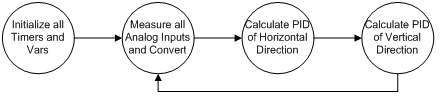
Controlling the Helicopters Heading (Horizontal Direction)
The horizontal IR Sensors were responsible for controlling the helicopters heading direction. The difference in readings between these two sensors was considered our error in the PID algorithm. Ideally, if the helicopter was facing directly between the two horizontal sensors, the error would be zero and the PID algorithm would try and sustain that heading with little to no oscillation. The standard PID algorithm is such that:
We learned that the most important terms of this algorithm were the Proportional (P) and Integral (I) terms. The raw output of the PID algorithm is what we used to determine the duty cycle of our PWM. We created a state machine that would control the motor speed in a linear fashion between the values of -255 and +255 and max out the motor (either left or right, where appropriate) when it exceeded these values. The state machine controlled the A and B channels of the 8-bit Timer0 PWM in such a way that, it would simulate the turning of the potentiometer device. So, if the helicopter was favoring one sensor more than the other, the PWM duty cycle would change and hence turn the helicopter in the opposite direction to correct itself. We went through many iterations of different PID values to get the helicopter to turn quickly and with no oscillations.
Controlling the Helicopters Throttle (Vertical Direction)
We controlled the helicopters throttle in a very similar fashion as we controlled the heading. We used the vertically spaced IR Sensors to control the PID algorithm after converting the analog signals to digital. We then used a similar PWM, this time using Timer1, to control the throttle potentiometer. We also implemented a safe check, so if the program went into a state where it could not recognize the helicopter at all, it would max out the motor to have it float instead of cutting the motor.
The ADC
The way we implemented using four analog signals was that after reading each one, we changed the MUX4:0 bits on the ADMUX register. This allowed us to seamlessly switch between which port pin we wanted to measure. After reading each input, we would wait for each conversion to end before reading in the next value. Each cycle, the program would record four digital values from our paddle for calculations.
The PWMs
We used, in total, four PWMs, two from Timer0 and two from Timer1. Our state machines controlled the output control registers directly from the output of our PID algorithm. These PWMs were then low-passed into our potentiometer devices to control the helicopter through the remote control board.
Global Variables
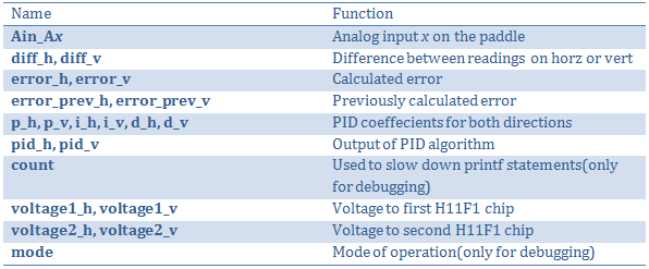
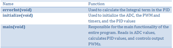
Functions
Hardware Details
Our hardware started with taking apart helicopter itself. It was easy to remove the main body panel allowing us to see all of the internal hardware. After an initial inspection we realized that we would be able to remove an LED on the front of the helicopter and replace it with an infrared LED of our own. This infrared LEDs purpose is to give our receiver information on where the helicopter was with respect to the paddle. We measured the voltage across the helicopter boards pin out and ground, which gave us around 4 volts. In addition we measured the max amount of current that could be produce from the target boards pin out. The max we were able to produce was around 40 milliamps. This was not enough current to power one of the LEDS in our lab, so we had to order an LED that had several specific qualities. One quality was a radiation pattern that was broad, rather than narrow. This allowed us to get good readings from each of the receivers rather than min values for each. Another quality we needed in the LED was to provide enough power with a minimum current. Our original tests showed that we werent able to receive data from the LED at 5 inches away. However, after finding the LED (365-1056-ND), we were able to successfully retrieve a strong signal at 6-8 inches away from the helicopter.
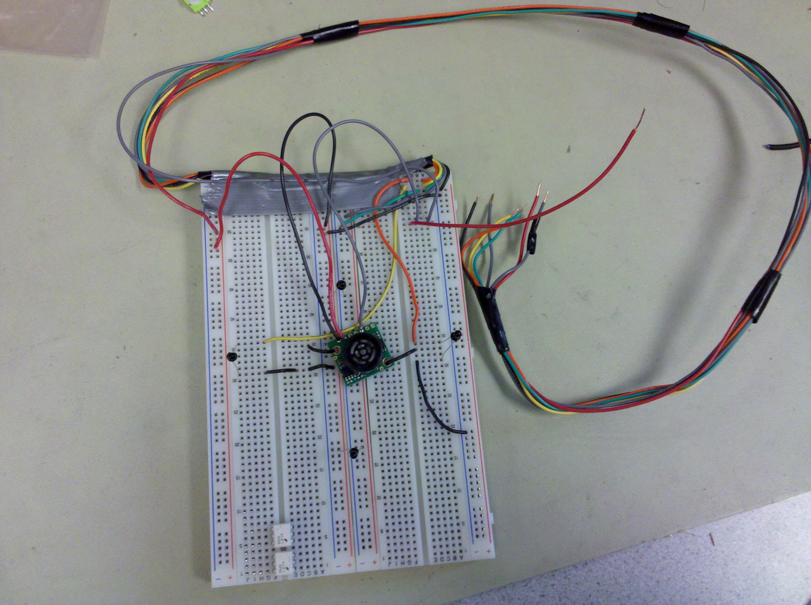
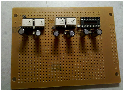
We then needed to build a paddle with 4 infrared receivers in a diamond formation in order to receive data from the helicopters emitter. The final design can be seen below. Each phototransistor was a LTR4206, used from lab.
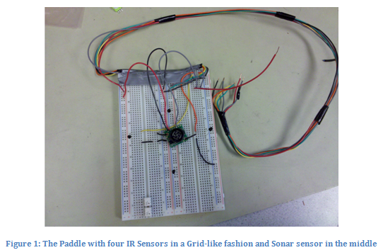
Each phototransistor then had an output between the resistor and itself used for an analog to digital port on our target board. This picture also includes a sonar system with an analog to digital connection as well. This was not used as the sensitivity was not good enough for our helicopter.
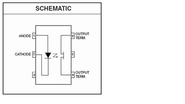
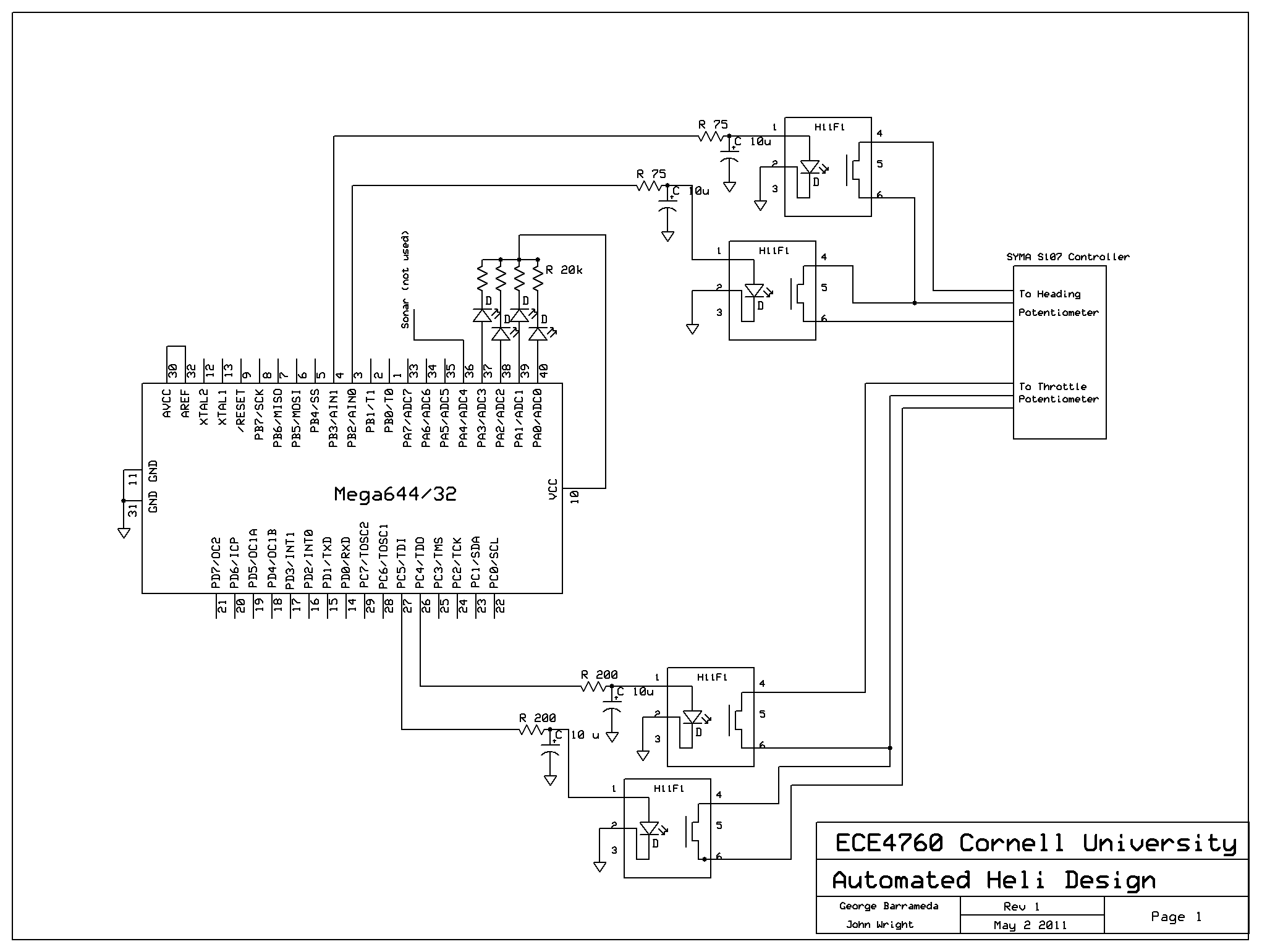
We also modified the actual controller that came with the helicopter. After taking apart the controller we were able to see that the circuit board controlled the horizontal, lateral, and vertical movement of the helicopter with potentiometers. Tilt was controlled internally by a gyroscope balancing algorithm. We decided to remove the potentiometers and create our own digital potentiometers. We used H11F1 opto-coupler chips in parallel to have an output resistance for each original potentiometer. The schematic for a single H11F1 can be seen below.
After consulting Bruce Land for our digital potentiometer design, we decided that we would use two chips for each original potentiometer to simulate the two end connections and a wiper. Our design for each digital potentiometer is as shown below.
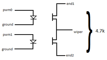
To get resistances out we have a pulse width modulator generate a voltage as described in the software section of this report. The final product of the digital potentiometer circuits is below.
The inputs to the H11F1s have a low pass filter. This filter stabilizes the pulse width modulated voltage for a stable output resistance. The far right empty socket was used to control lateral motion but was unused due to issues with the gyroscope described in the issues section of the report.
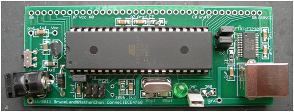
Instead of using the STK500 we decided to build a target board that was significantly smaller. The board used was a mega644 prototype board designed by Bruce Land. We mounted all the components seen below onto the board by soldering.
Ideas That Did Not Work
Controlling Pitch using SONAR
We initially were cautious about being able to control the pitch (forward and backward motion) of the helicopter because we werent sure if we could make it stable enough for proper demonstration. After we had the some control of the throttle and heading of the helicopter, we decided to give it a shot. We bought an Ultrasonic Range Finder (Maxbotix LV-EZ4 x1) and centered in the middle of our IR sensor grid to determine how far away the helicopter was at all times. We used the analog output of the sonar device as an input into our target board and read it in with the software. What we learned is that the device would only output a difference of ~9.8mV/inch. We tried to boost this signal using op-amps and the embedded gain functionality of the Mega644 chip, but we also learned that changing the pitch of the helicopter would cause the program to think that the helicopter had an erroneous vertical displacement which would cause issues in flight. Eventually, we had to scrap this idea since the noise on the signal was too great and the control of the other two directions became unstable using SONAR.
Feeding Voltages Directly to the Controller Board in lieu of a Potentiometer
We initially measured the voltages across the wiper and ground pins of the potentiometer to learn what voltages mapped to what directions. We thought that if we were to just put similar voltages across those pins, the outputs would control the helicopter easily. However, we learned that the resistance across the wiper and output was what controlled the helicopter. It made our design much more complicated since we had to use H11F1 devices which did not act as linearly as we thought. So, we basically had to continually plug in different voltages into the chip and measure the voltages that were actually being read through the controller and create a table mapping that way.
Speed of Execution
We measured the speed of execution based on how long it took the helicopter to correct its position. This relied heavily on the PID values, as well as the speeds that we deemed safe for the helicopter to react with. For instance, we did not want the helicopter's throttle to exceed a certain range where we thought it would fly out of the grid and become unstable. The helicopter's heading was the simpler of the two to implement. After numerous iterations, we got the helicopter to center itself without oscillations in below 4ms. We did this by scoping the output of the low-passed PWM and measuring the time scale until the oscillations ceased. The vertical centering was a lot more difficult, We decided to prioritize stability instead of speed so our helicopter would shoot out of range of the paddle.
Accuracy
Our helicopter's accuracy was solely dependent upon whether it could virtually stay centered in the middle of the paddle. We measured this using the output of the four IR sensors. The purpose of the PID algorithm was to calculate the error of the location of the helicopter vs the middle of the paddle. We were able to see a 2-3 centimeter accuracy error which tracking horizontally only. We saw a 4-6 centimeter accuracy when tracking vertically. During demonstration we were able to effectively maneuver the helicopter at between 6-15 centimeters away from the paddle. However, the responsiveness of the throttle control was not as accurate and required some patience when using. Again, stability was prioritized over accurate control of the throttle so this was a trade-off that we deemed appropriate for demonstration. In addition to this, the accuracy was affected heavily by the battery life on the helicopter. As the battery's charge drained, the accuracy decreased.
Safety
The main safety concern with our project is what the helicopter does when it loses sight of the paddle controller. The way weve enforced this is by setting default helicopter control commands for when the paddle isnt in sight. For example, if the helicopter is hovering and loses sight of the controller, it will safely coast down to the floor. The same goes for when the helicopter is spinning.
A secondary safety concern was what the helicopter would do when it is initially turned on. We installed a start pushbutton. When the helicopters main controller is turned on, it wont start flying until the start button is pushed. This allows the user plenty of time to line the paddle up with the helicopter before it starts to fly.
Interference
We had little to no interference, except for some IR radiation from the fluorescent lab lights. However, this did not cause many problems at all since we rarely pointed the paddle straight up into the ceiling.
Usability
Our helicopter's usability during demonstration was good. We were able to control the rotational calibration of the helicopter in all 360 degrees. We were also able to control the helicopter's hovering and move it up and down vertically in the air. The demonstrations maximum time length was around 30-45 seconds of sustained flight. The reason for this is that the helicopter had a "sliding" motion through the air. The helicopter was very light and was affected by light air currents pushing it through the air. Because of this, we would often have to catch the helicopter and reset its position to continue demonstration. This usability issue would have been fixed with any form of lateral helicopter control, which we were unable to implement using our gyroscope.
The usability of our helicopter for the public would require a slightly larger scale. The helicopter would need to be big enough to support a larger battery for sustained flight control, as well as improved LED current for positional control. With a larger helicopter, gyroscope measurements would work better and would allow it to have lateral position control. This would eliminate the sliding motion in the air.
Results vs Expectations
Remote controlled helicopters are notorious for being unstable and difficult to control. Initially, we were skeptical to see how we could control a helicopter with little oscillation and with enough stability to demonstrate without issue. We were expecting our helicopter to oscillate up and down and left and right in a sort of hunting manner. We also expected to be able to control the helicopter in three degrees using sonar to control the pitch (forward and back motion). Finally, we expected the control of the helicopter to be as trivial as tapping voltages to the remote controller.
The results of the project were both higher than expected and below expected. The use of IR sensors was much more complicated than we expected and it turns out that the viewing angle and intensity of the IR emitter was crucial in determining the accuracy of helicopter flight. We initially wanted to replace the helicopters multi-colored LED with an IR one of similar size. The forward voltage of this IR emitter was 1.7 V and its viewing angle was about 15 degrees. It turned out that the viewing angle was much too small to get register on the both IR sensors of the paddle, and its low intensity made our range of operation way too small for demonstration. We ended up going with a much larger 4.0V IR emitter with a viewing angle of 20 degrees.
Tapping voltages to control the helicopter via the remote controller was also not possible. We needed to simulate an analog potentiometer with the H11F1 device which made the project much more complex and with little linear control.
We actually expected SONAR to be the easiest part of the project. By getting a PWM or analog output of the device, we would be able to accurately control pitch and distance from paddle. However, it turned out that our range of flight was much too short for the SONAR to accurately measure and boosting the signal gave us too much noise to control the helicopter in a stable manner. Finally, as the helicopter dips to move forward, the IR LED points to the bottom IR sensor making it seem like it is further down than it actually is, causing the program to become unstable.
As far as overall control goes, we exceeded our expectations about how quickly the helicopter can correct itself. As we move the paddle from left to right, the helicopter immediately finds the center without oscillating at all. It also has a very quick reaction time. We were also correct to assume that the throttle would be very hard to control. We thought that we would have a free flying helicopter, but due to stability concerns, we had to tie down the helicopter in order to protect it from getting damaged.
If we were to restart the project, I think that we would have focused more on getting brighter LEDs with larger viewing angles. This would help our helicopter be more stable in flight. Also, we would have looked into purchasing digital potentiometers that take in a value and output a resistance. We spent most of our time trying to map out input voltages and output resistances that were non-linear. If we could have just inputted a value and got an expected one, digital potentiometers would have greatly reduced the complexity of this project.
Design Conformance to Standards
Our design doesnt conflict with any regulations at all. We modified the controller that was already part of the purchased helicopter package, which uses LED control. In addition to this we added a single low power LED to the helicopter. The FCC states that it allows unlicensed low power short-power devices, which our project falls under. Neither of our modifications violates any regulation. However, if we were to use radio signals in a future project rather than LEDs we may have had to conform to other FCC standards.
We use a wall socket power supply that has the potential for large current. However, all the safety regulations for the FCC are covered in the actual wall socket plug itself.
Intellectual Property
Our baseline code was derived from ECE 4760s blinky_serial_GCC644.c program since we used it as baseline tests when constructing our target board. The only code that remained implemented in the final design was the included library headers and some of the program structure. We did not copy and code from the public domain.
We are using the remote controllers board provided in controlling the Syma S107 RC Helicopter. We are not claiming the board as something that we designed, but we just retro-fitted it with our own potentiometers and power supply.
Ethical Considerations
In compliance of the IEEE code of ethics, we attempted to follow all the ethically guidelines when creating this project. We have had good interactions with everyone weve spoken to during this project including our professor and other classmates. When other classmates had issues we tried our best to help them in any way possible. We have been respectful when using the equipment in the lab. This includes not overusing the soldering station when other students were in need of the same equipment.
We have been honest in all of our reporting including our budget and have credited those who are due credit to our project. In addition to this, we have not violated anyones intellectual property.
When partnering up together we let each other know our strengths and weaknesses in microcontroller design. At no point did we deceive each other on what we had been working on or what we were able to do. We communicated often with each other and at the beginning of the project, collaborated well to pick a project that we knew we would both enjoy.
This project spanned over four full weeks. We spent equal amounts of time working on this project and believe that following ethical guidelines was the only way to get through the project in a good way.
Legal Considerations
Our project was planned, designed and implemented based primarily on our ability and without engaging in any illegal practices. Our project was essentially a modified toy helicopter using IR LEDs as a form of remote communication and control.
Acknowledgments
The original basis of our project came from Kayla DesPortes, Jayashree Kumar, and Zechariah Dzegede and their Flexicopter project
We would also like to thank Bruce Land for his endless help on our project design and debugging.
//*********************************
// George Barrameda; gmb67
// John Wright; jdw229
// ECE 4760 FINAL PROJECT SP'11
// Automated Helicopter Flight
//*********************************
//Header Fukes
#include <inttypes.h>
#include <avr/io.h>
#include <avr/interrupt.h>
#include <stdio.h>
#include "uart.h"
// UART file descriptor -- putchar and getchar are in uart.c
FILE uart_str = FDEV_SETUP_STREAM(uart_putchar, uart_getchar, _FDEV_SETUP_RW);
unsigned char Ain_A0, Ain_A1, Ain_A2, Ain_A3, Ain_A4; //Raw ADC Inputs
signed int diff_h, diff_v; //Difference Values between IR Sensors
// PID Variables
signed int error_h, error_prev_h, error_int_h, pid_h;
unsigned int p_h,i_h,d_h;
signed int error_v, error_prev_v, error_int_v, pid_v;
unsigned int p_v,i_v,d_v;
int count; // Limits printf statements to console
int voltage1_h,voltage2_h,voltage1_v,voltage2_v; // Input Voltages to Controller
char mode; // Flight mode (1 == hover mode) for debugging
// Error Integral Task
// Calculates the Integral term of the PID
void errorInt(void) {
if ((error_h > 0x00) && (error_prev_h < 0x00)) {
//Sign change, zero the term
error_int_h = 0;
} else if ((error_h > 0x00) && (error_prev_h < 0x00)) {
//Sign change, zero the terms
error_int_h = 0;
} else {
//No sign change, continue adding to the integral
error_int_h += error_h;
}
}
// Initialize Task
// Initializes the UART, ADC, PWMs, PID parameters and all Timers
void initialize(void) {
///////////////////////////////////////////////////////
// Initialize ADC
///////////////////////////////////////////////////////
//Initialize the A to D converter
//Channel zero/Left Adj
//Set AREF to Vcc
ADMUX = (1<<ADLAR) | (0x40);
//Enable ADC and set prescaler to 1/128*16MHz=125,000
//And clear interupt enable
//And start a conversion
ADCSRA = (1<<ADEN) | (1<<ADSC) + 7 ;
///////////////////////////////////////////////////////
//Init the UART -- uart_init() is in uart.c
uart_init();
stdout = stdin = stderr = &uart_str;
fprintf(stdout,"Starting ADC demo...\n\r");
//Intialize PID
p_h = 5;
i_h = 10;
d_h = 0;
error_h = 0;
p_v = 5;
i_v = 10;
d_v = 0;
error_v = 0;
count = 0;
///////////////////////////////////////////////////////
// Initialize PWMs
///////////////////////////////////////////////////////
// TIMER0 PWM
DDRB = (1<< PINB3) | (1<< PINB4); // make B.3 and B.4 an output
TCCR0B = 0x01; // timer 0 runs at full rate
TIMSK0= (1<<TOIE0) ; //turn on timer 0 overflow ISR
// turn on PWM0
// turn on fast PWM and OC0A/B output
// at full clock rate, toggle OC0A (pin B3 and B4)
// 16 microsec per PWM cycle sample time
TCCR0A = (1<<COM0A0) | (1<<COM0A1) | (1<<COM0B1) | (1<<COM0B0) | (1<<WGM00) | (1<<WGM01) ;
OCR0A = 0 ; // set PWM to half full scale
OCR0B = 128;
DDRD = (1<< PIND4) | (1<< PIND5);
TCCR1B = 0x01;
TIMSK1= (1<<TOIE1) ;
// turn on PWM1
// turn on fast PWM and OC1A/B output
// at full clock rate, toggle OC0A (pin D5 and D4)
// 16 microsec per PWM cycle sample time
TCCR1A = (1<<COM1A1) | (1<<COM1A0) | (1<<COM1B1) | (1<<COM1B0) | (1<<WGM11) | (1<<WGM10) ;
OCR1A = 0;
OCR1B = 128;
// Flight Mode (user input) for debugging
fprintf(stdout, "Mode?");
fscanf(stdin, "%d",&mode);
}
// Main Task
//
void main(void) {
initialize();
while (1) {
///////////////////////////////////////////////////////
// ADC Code
///////////////////////////////////////////////////////
ADMUX = ADMUX & 0xF0; //Run A/D off of A0
Ain_A0 = ADCH; //Get the sample
ADCSRA |= (1<<ADSC); //Start another conversion
while (ADCSRA & (1<<ADSC)) {} //Wait for conversion to complete
ADMUX = ADMUX & 0xF0;
ADMUX = ADMUX | (0x01); //Run A/D off of A1
Ain_A1 = ADCH; //Get the sample
ADCSRA |= (1<<ADSC) ; //Start another conversion
while (ADCSRA & (1<<ADSC)) {} //Wait for conversion to complete
ADMUX = ADMUX & 0xF0;
ADMUX = ADMUX | (0x02); //Run A/D off of A2
Ain_A2 = ADCH; //Get the sample
ADCSRA |= (1<<ADSC) ; //Start another conversion
while (ADCSRA & (1<<ADSC)) {} //Wait for conversion to complete
ADMUX = ADMUX & 0xF0;
ADMUX = ADMUX | (0x03); //Run A/D off of A3
Ain_A3 = ADCH; //Get the sample ;
ADCSRA |= (1<<ADSC) ; //Start another conversion
while (ADCSRA & (1<<ADSC)) {} //Wait for conversion to complete
///////////////////////////////////////////////////////
///////////////////////////////////////////////////////
// PID Code
///////////////////////////////////////////////////////
// PID - Horizontal
diff_h = Ain_A1 - Ain_A2;
error_prev_h = error_h;
error_h = diff_h;
errorInt(); //Calculate the error integral
pid_h = p_h*error_h + (i_h*error_int_h)/1000 + d_h*(error_h - error_prev_h);
voltage1_h = 180;
if (pid_h < -255) {
voltage2_h = 275;
}
else if (pid_h < 0) {
voltage2_h = 275 + (112 + (pid_h/255)*112);
}
else if (pid_h < 255) {
voltage2_h = 387 + (pid_h/255)*112;
}
else {
voltage2_h= 500;
}
OCR0A = 255 - (voltage1_h/500.0)*255;
OCR0B = 255 - (voltage2_h/500.0)*255;
// PID - Vertical
diff_v = Ain_A0 - Ain_A3;
error_prev_v = error_v;
error_v = diff_v;
//errorInt(); //Calculate the error integral
pid_v = p_v*error_v + (i_v*error_int_v)/1000 + d_v*(error_v - error_prev_v);
voltage1_v= 0;
if (mode == 0x01) {
voltage2_v = 500;
}
else if (((Ain_A0 > 250) && (Ain_A3 > 250))) {
voltage2_v = 175;
}
else {
if(pid_v < 0) {
voltage2_v = 0;
}
else {
voltage2_v = 250;
}
}
OCR1A = 255 - (voltage1_v/500.0)*255;
OCR1B = 255 - (voltage2_v/500.0)*255;
///////////////////////////////////////////////////////
if (count == 300) {
//results to hyperterm
printf("A0 out: %d, A1 out: %d, A2 out: %d, A3 out: %d, Sonar: %d\n\r",Ain_A0,Ain_A1,Ain_A2,Ain_A3,Ain_A4);
printf("diff_h= %d\n\r", diff_h);
printf("pid_h= %d\n\r", pid_h);
printf("diff_v = %d\n\r", diff_v);
printf("pid_v = %d\n\r", pid_v);
count = 0;
}
count++;
}
}
Click for Larger Image
DataSheets
Mega644 DatasheetA/D and D/A on Mega32
Mega 644 Prototype Board
H11F1
Phototransistor 160-1030-ND
LED Emitter 365-1056-ND
Vendor Sites
DigikeyEthics
IEEE Code of Ethics