CORNELL
UNIVERSITY ECE 4760 FINAL PROJECT
Introduction
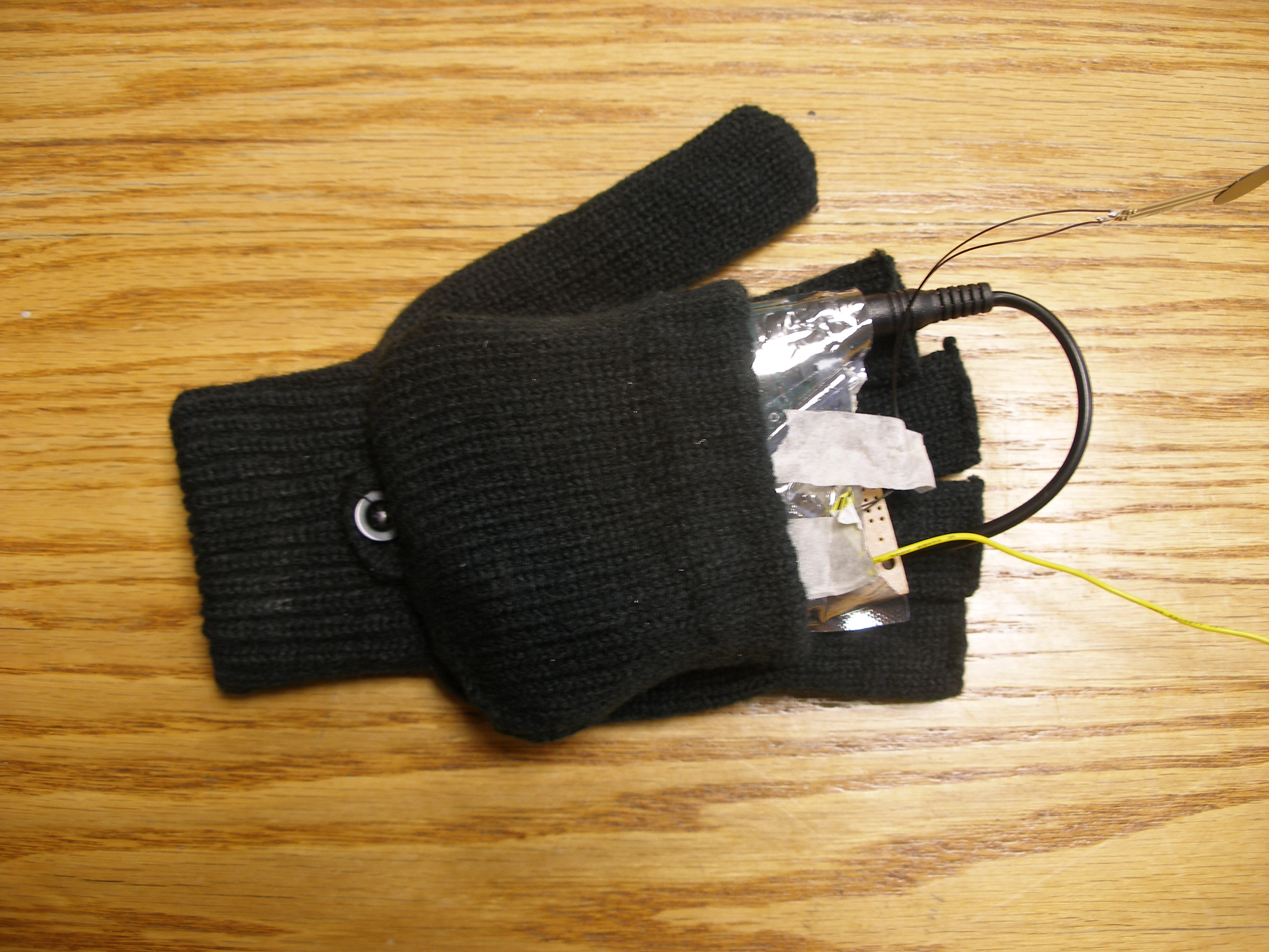
Our project is a
novel hand held
controller in which we use an accelerometer to wirelessly control the
motion of
a Parrot AR Drone Quadricopter.
Rationale:
The main idea of our
project was
building a cool glove controller for a flying platform, a quadrotor in
this
case, which would give the user a different sense of power over the
robot,
unlike conventional controllers like the Xbox controller. Even though this is an ambitious project that aims to make a
moderately good controller, it can open the way to further development
for this type of controllers for flying platforms. This is another
reason for using a quadrotor from the Robot Learning lab. One of the
team members(Mevlana Gemici) is merging this project with his project
and research in the Robot Learning lab which is administrated by Prof.
Ashutosh Saxena. This also allowed the quadrotor to be kept out
of the budget considerations.
Background math:
Other than very
simple math, we didn’t need to do many calculations for our
project. In fact,
other than integration (very simple summing in time steps) in the
receiver end,
there is nothing worth mentioning.
High Level Design and
Logical structure:
Program/Hardware
Design
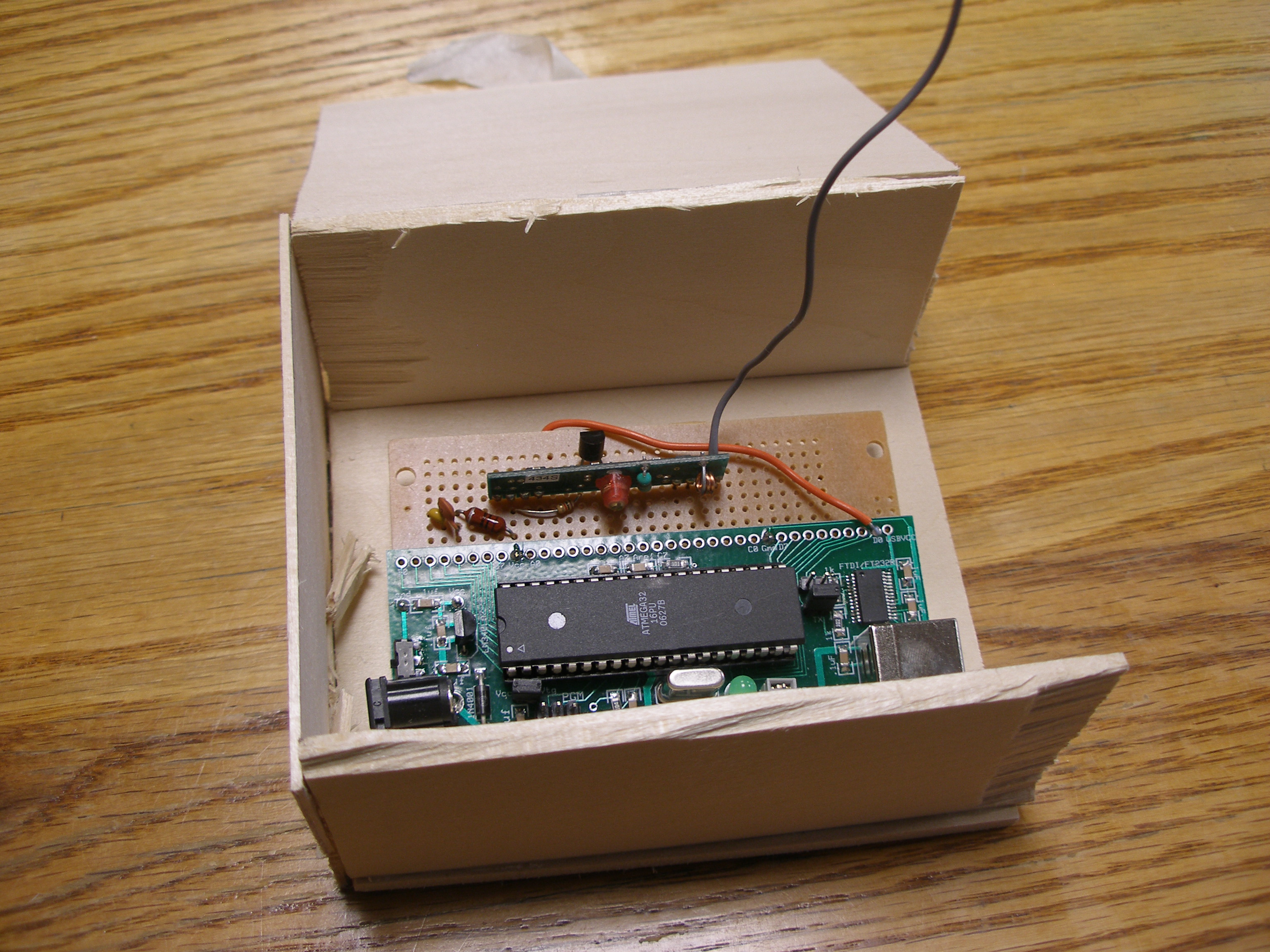
We utilized the
ATMega32
microcontroller in our program. Although we initially wrote our code
for the
ATMega644 microcontroller, we switched to using the ATMega32 chip, as
it
required only changes in registers names in the ATMega644 code.
We took care to
select parts that
were available in DIP packaging, so we could solder on to a prototype
board.
Since we did not ask
for any
samples, we cut the budget fairly close. We already had several of the
necessary items – the gloves and battery connectors/converters
available so we
did not count that in the budget.
Accelerometer
The accelerometer we
chose was
the ADXL335, which including a breakout board, we obtained for $20 from
Adafruit. Our choice of this module was motivated by several factors.
We needed
a low-G accelerometer, since the acceleration that is being detected
would not
be too great, as our application would be controlled by a user moving
his/her
hand. Furthermore we wanted movement in the x, y, and z directions, and
therefore we needed an accelerometer that can sense movement in all
three of
these axes. Furthermore, the accelerometer must be both low cost and
available
on a breakout board, as the cost of a PCB would definitely cause this
project
to run over-budget.
The accelerometer
runs on voltage
supplies of 1.8V to 3.6V. We opted to use 3.3V regulator along with a
separate
9V battery to power the module. Initially we attempted to use a simple
op-amp
voltage shifter to shift the 5V from our microcontroller power supply
to the
3.3V needed. However, the supply voltage provided by this setup proved
to
fluctuate quite a bit, causing the acceleration values from the
accelerometer
to fluctuate along with it, making it difficult for us to detect when
it was
actually accelerating. Therefore, we decided to swap to using the 3.3 V
regulator and a separate power supply altogether, despite the increased
weight
of the extra 9V battery. This resulted in much more stable
accelerometer
readings.
We oriented the
accelerometer
such that the x axis was indicative of forward/backwards motion, the y
axis
indicates right/left motion, and the z axis indicates up/down motion.
Therefore, at rest, there is 0g acceleration on the x and y directions,
but
there is a constant -1g on the z axis caused by gravity. At 0g
acceleration,
the voltage present on the outputs from each axis should be Vs/2, where
Vs is
the supply voltage provided to the accelerometer, which is 3.3 V in our
case.
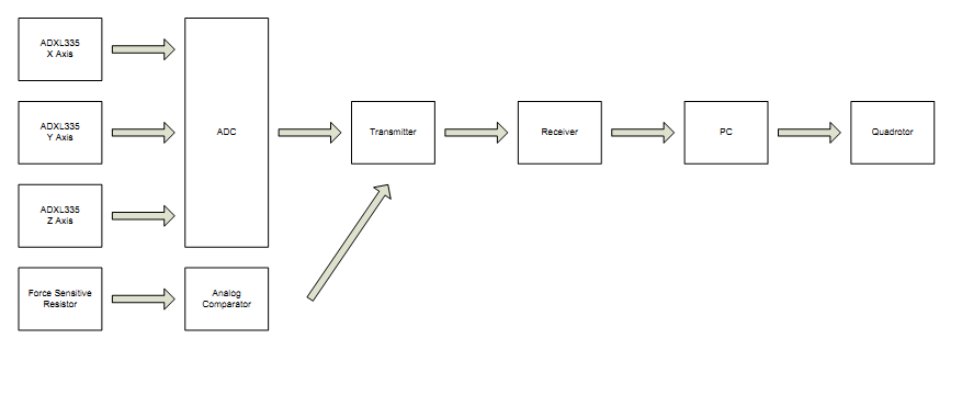
To acquire data from
the
accelerometer, we used the internal ADC in the microcontroller. The
analog
signals were connected in single ended channel configurations as
follows - the
z axis was connected to AD0, the y axis to AD1 and the x axis to AD2 of
the
microcontroller. As the ADC can only read one analog channel at a time,
we used
the internal multiplexer in the AVR to switch between these three ADC
channels.
The ADC value is read in the ADC interrupt service routine, which is
called when
the ADC has finished reading a value. We read all 10 ADC bits- that is
from
both the ADCL and the ADCH registers - but in retrospect, we only
needed to
read 8, as we ended up discarding the two least significant bits in
order to
compress the data to 2 bytes, as we can only send a limited amount of
bytes in
each data packet from the transmitter to the receiver. More on this
will be
elaborated in the section on wireless communication below.
Once the data was
acquired at the
receiver microcontroller, we output information acquired from it to the
PC in a
very specific format. Instead of sending the ADC values directly to the
PC, we
chose to send the change in the ADC values – that is, the change
in the acceleration.
While acceleration can be obtained by subtracting the rest position ADC
value
from the newly acquired ADC value, if we hard coded the ADC rest value
in, it
would confine the user to start at a very specific accelerometer
orientation,
and therefore would probably not be suitable for use on a glove one
would be
wearing. Therefore, we chose to send the change in acceleration. Doing
so made
determining direction of motion slightly harder than it would have if
we simply
passed in acceleration data because then it would have been possible to
perform
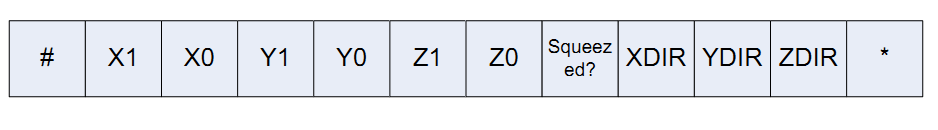
Euler integration to obtain a rough velocity value. The format in which
we sent
data into the PC is as in the picture below. X1 is the tens digit of
the change
in x acceleration and X0 is the ones digit. XDIR is 1 if the change is
positive, and 0 if there is no change or it is negative. The same
applies to
Y1, Y0, YDIR, Z1, Z0, and ZDIR. Squeezed is 1 if the force sensor was
toggled
on and 0 if it is toggled off. Each data string starts with # and ends
with *
for easy identification in parsing.
Force Sensitive
Resistor
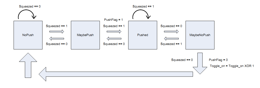
The force sensitive
resistor we
used was an Interlink 402, purchased from Adafruit Industries for
$7.00. We
utilized it in a similar fashion as the pushbuttons in lab 2 and
therefore used
a debounce state machine.
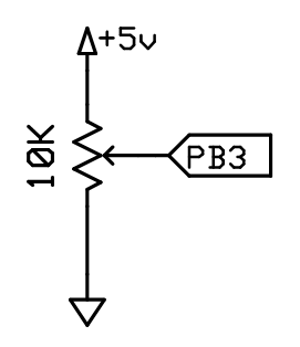
The variable squeezed is 1 if the force sensor is pressed. We use the circuit in the below diagram to detect when the force sensor is pressed. When the force sensor is not pressed, its resistance is in the MOhm range. When it is pressed, its resistance approaches a short circuit. We therefore use the analog comparator to detect when the voltage rises above a certain value by setting it to detect on rising edge. This value can be set using a potentiometer and is useful for setting how sensitive a squeeze the sensor can register.
Even though we implemented the hardware as well as the software for this force sensor button, we couldn't find a good use for it since take off and landing was controlled by another mechanism. However, we are planning to use this part in further development and research on this controller in the Robot Learning lab. One suggestion that we are considering is using this sensor to toggle on/off the control to allow longer motions without having to pull back the hand while the quadrotor is controlled. This would provide easier user control as was suggested by our TA, Rohan Sharma.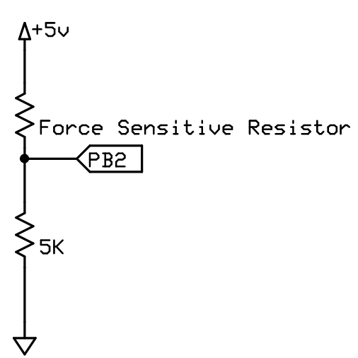
Wireless Communication
For the wireless
communication
between our transmitter unit and the receiver unit, we utilized the
RCT-433-AS
transmitter and the RCR-433-RP receiver, both from Radiotronix and
provided by
Professor Land. The communication protocol we used was heavily adapted
from
Meghan Desai’s Wireless Transmit and Receive Project Report on
the course
website. We made several modifications to it to better suit our project.
The original
communication
protocol on Meghan Desai’s page utilizes the following method to
transmit data.
The full documentation for his protocol is listed in the appendix below.
The transmitter sends
data to the
receiver through on-off keying, in which a logic 0 is transmitted by
turning
the transmitter off and a logic 1 is sent by turning the transmitter
on, which
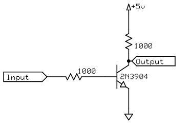
sends out a carrier. In this configuration, the transmitter idles at
logic 0.
As the UART of the microcontroller idles at logic 1, the signal must
first be
passed into an inverter before being sent to the transmitter and the
output
from the receiver must then be inverted again. The inverter we used was
a npn
transistor placed in common emitter mode in the following
configuration.
Professor Land suggested using 1kOhm resistors for best performance.
The original protocol
involved
sending data from a transmitter to a receiver at a baud rate of 4000.
However,
as this is a non-standard baud rate, it was difficult to interface it
properly with
the PC, as we not used the USART ports of the microcontroller on the
receiver
end to accept data from the radio, we also used it to send data to the
PC over
a serial USB connection. Therefore, we elected to utilize a baud rate
of 4800,
which also happens to be the maximum speed at which the transmitter can
transmit to the receiver. This was done by setting the UBRRL register
to 207,
as referenced from Table 68 in the ATMega32 datasheet. This can be
obtained
through the following formula:
(Table
60, Page 143,
datasheet)
Note that this value of UBRR will give an error rate of 0.2%, which we feel is sufficiently small that it can be ignored. The error can be obtained from the equation:
(Page
165 Datasheet)
We
were able to acquire
good data at this maximum speed, but we also had some issues regarding
packet
size. Using the original protocol, if we attempted to transmit data
beyond 6
bytes, the packet contents would end up not being received properly
– e.g. the
values of the bytes at the end of the packet will have changed to
different
values. The data that we needed to send from the transmitter to the
receiver
was the acceleration values for the three axes, a bit representing
whether or
not the force sensor was pressed, and so therefore we had to modify the
transmission protocol slightly so that we could transmit all the data
we
needed.
The
modified packet
that is sent from the transmitter appears as follows:
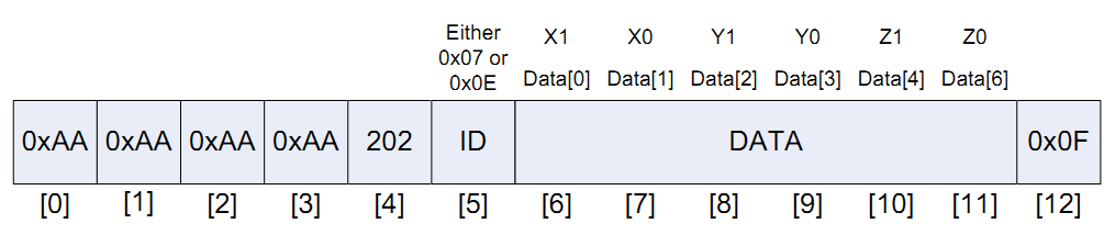
The
first 4 bits are
the 0xAA that Meghan Desai’s protocol uses for synchronization
purposes and the
bit 4, 202, is the start character. The ID we set such that it was 0x07
if the
force sensor was toggled off and 0x0E if the force sensor was toggled
on. By
limiting our ID to these two specific values, we were able to use this
as one
of the many checks to determine if the packet we obtained at the
receiver was
really ours. Following the ID are the 6 bytes of data, 2 bytes each for
the 8
most significant bits of the x, y, and z ADC accelerometer values. We
check
these values to make sure that each data char we obtain at the receiver
is less
than or equal to 0x0F – that is, one byte. In addition, we added
one extra
character, 0x0F, at the end of the packet that is used to determine if
the
packet we obtain is valid. Sometimes, the first several parts of the
packet are
correct but the last part of the packet is not. This occurs especially
when the
transmitter antenna is shakes. Therefore, by inserting this character
to check
at the end of the packet we could use it to help determine if the
packet is
correct. A packet of this size is around the maximum we could send
– longer
packets were not received properly.
Difficult parts and
other things we
tried before settling on the final design
As mentioned
previously, we
initially opted to use an op amp differential amplifier voltage shifter
to
provide the 3.3V power supply that the accelerometer required. This circuit assumed that the input
difference at the + and – terminals was 5V and provided 3.3V at
the output.
With zero input voltage, the circuit provided 0V. While this circuit
did give
us the necessary voltage, it fluctuated quite a lot, which meant that
the input
voltage was fluctuating around 5V. We verified this with a multimeter
and
suspect that this may be due to the transmitter. This made it difficult
to
determine whether or not the accelerometer was actually being moved or
if the
change in acceleration we calculated was due to these supply voltage
fluctuations, as the resting voltage potential at each accelerometer
output is
determined by Vs /2. Therefore we made the decision to switch to both a
separate power supply and 3.3V regulator as described previously and
this
pretty much solved our problem.
We spent a great deal
of effort
attempting to get Meghan Desai’s original receiver and
transmitter code to
work. In the end, it took many modifications in the code, some of which
do not
seem immediately intuitive to get the code working. Furthermore, we
noticed
that it was necessary to pad data bytes at the transmitter with 0x0F or
0x00
depending on which number is being sent or the received value will not
be
correct. To anyone looking to use these radios and the protocol in a
future
project, we would like to mention that a decent amount of time and
effort should
be budgeted to spend on getting the radios to work properly.
Another approach in
this project
that we tried was amplifying the accelerometer output in order to get
better
sensitivity. It turns out that this was not necessary and we eliminated
the
amplifiers from the final circuit.
Range of the Radio
Even
though we are not sure we
have tested it to its limits we can say that the range of the radio is
around
20 meters. Since we were testing the quadrotor and the radio in a room
setting,
we are not sure how it would behave in open environments.
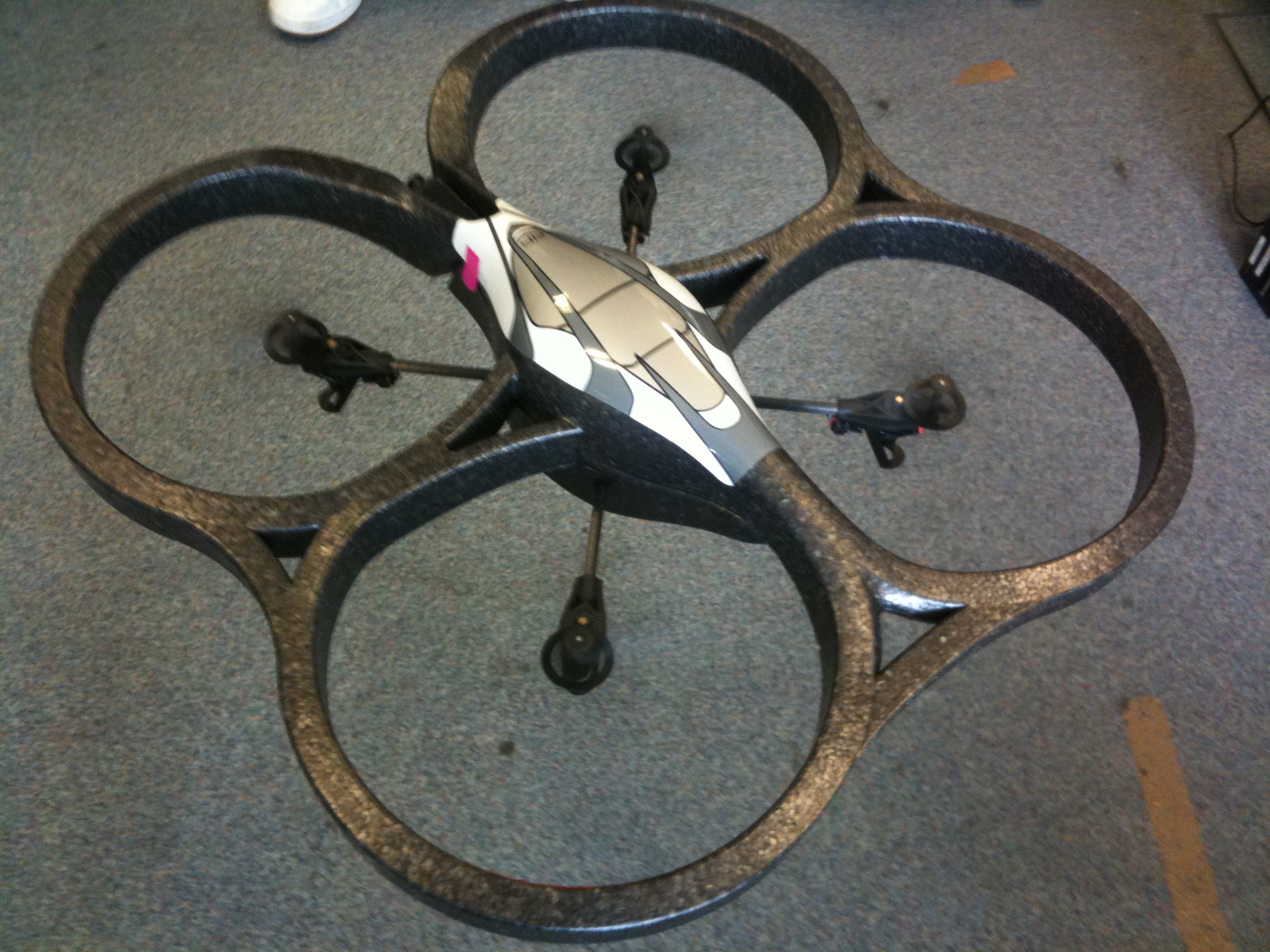
ADrone Parrot
Quadrotor
We used a Parrot Quadrotor as our flying
platform
which is connected to and controlled through wireless from a computer
that runs
an application code using its API in Linux. In order to interface with
this
application program, we used the various IO libraries provided by the
Linux
distribution(Ubuntu 10.10) that we were using and wrote a small driver
to get
the 4800 baud rate serial data from one of the USB ports. The serial
port was
connected to the receiver end MCU which sent the data we acquired from
the RF
link to the channel in a formatted way(with start/end characters) as
explained
previously.
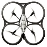
The quadrotor uses four propellers and has
the
ability to move up/down, change its yaw to turn around, move
forward/backward
by changing its pitch and go sideways by rolling right/left. Since we
had three
axes for the glove controller, we could use the force sensor as a
switch
between yaw and roll control. However, controlling the roll seemed
quite dangerous for the robot with a sometimes unstable controller.
Thus we choose to omit the roll control. Since for each of the x,y,z
channels, the
data
that was being acquired contained some errors, either due to the
accelerometer
or the radio transmission, we selectively determined the data in a
series of
transmissions that made sense as valid to get rid of these errors.
We used the x axis as the pitch controller.
As the
hand is moved forward, the quadrotor’s pitch is set to a value
proportional to
the value of the received acceleration. However since the hand motion
created
some immediate spikes in the acceleration data that followed the
initial
movement we chose to consider only the first data that is acquired
after a long
series of zeros. This proved to be considerably more robust for the
pitch
setting.
Y axis of the glove controller is used in
two
different ways depending on whether the force sensor was activated or
not. If
it is inactive(0), this axis is used for setting the yaw of the
quadrotor. If
it is active(1), then the axis determines the sideways roll of the
quadrotor. However this was disabled at the final design for safety
purposes as mentioned before.
The data we get from this channel is also shows some spikes but
the
first two data points seems to be a good indicator of the glove
(instead of one data point as in the x axis) which we integrate(sum in
this case) in each time step in a
weighted
manner and then set the motor values. This axis is used in a dynamic
manner to
keep its motion until a balanced motion is applied in the opposite
direction
since this seems to give the user a better ability to control the
quadrotor for
yaw.
The z axis was used to make the quadrotor
move
vertically. After getting rid of the spikes in a similar fashion to the
other
axes, we set the rotor power(dgaz_final variable in the code)
proportional to
acceleration sum that is calculated.
All the variables that we set for these
four
parameters are represented as velocities(sometimes angular) in these
directions
and take values between -25000 to 25000 which was determined by the API
that
was provided.
Even though we are controlling the
quadrotor once it
is off the ground and its algorithms are activated, we didn’t
attempt to change
the internal mechanisms of the application and the API that uses a Xbox
controller
to take off, enable algorithms and auto-pilot landing since this was
beyond the
scope of this project. Also having a separate controller that works,
allowed us
to safely land the robot without any damage in case of a wrong motion
command
or dangerous environment. It also prevents an intruder to take control
of the
robot using the radio transmission since the algorithms must be enabled
locally
in order to send command signals that will be registered as valid.
Application program and API
Even though we are not going to attempt to
explain
all the details of the source code that was provided, we can say a few
words on
the tread that we used in the application that was provided by Cooper
Bills
from Cornell University’s Robot Learning Lab, which can be
downloaded
from the CS 4758 Robot Learning course website:
http://www.cs.cornell.edu/Courses/cs4758/2011sp/materials/ardrone_codebase_r10.zip
This codebase also includes that API that
is
necessary to interface with the quadrotor.
The application program uses many
concurrent treads
that provides different functionalities, including sensor data
processing,
motor control, camera image feed processing, and Xbee control. The
tread we
used(planner.cpp in the codebase) was designed to run algorithms when a
button on
the Xbox controller is pressed and set the motor control commands
according to
the results of the algorithms. This provides a safe layer that
doesn’t have to
deal with low level mechanics of the whole system. This is the only
file we
changed since we didn’t need to separate our code on different
treads. The
serial connection driver was also implemented here using mainly the
termios.h
file that comes with standard Ubuntu distributions. Therefore we will
only
upload the planner.cpp in our project website along with a link to the
original
rl_codebase10 as presented above.
Enforcing safety in
the design
Safety was an
important issue for
us, given that we were manually manipulating the movement of a decently
large
flying object – the quadrotor. The Parrot AR Drone Quadricopter
already comes
with numerous safety features – for instance, it locks its motors
if one of
them encounters resistance. Furthermore, it comes with a Styrofoam hull
that
protects it from crashes and also shielding the blades from the end
user. Regarding
safety considerations of our hand held controller, we performed
extensive
testing so that the patterns of acceleration change that correspond to
the
movements characteristic of forward, backward, sideways, and vertical
motion
can be detected properly in the vast majority of cases. In addition, we
highly
stress the importance of operating the quadrotor in a large open space
with
minimal obstructions and in its operation by skilled users.
Conclusion
The slower data rate, can be attributed to the fact that the data has
to travel through two wireless channels - the radio and the wifi.
So how would we do things differently next time? We would definitely
use a better radio such as the Xbee, which transmits at much higher
data rates and is easier to interface with a PC.By switching to a
different radio, we would probably have saved much
more time that could have been used to implement more hardware and send
more data from the transmitter.
Furthermore, we would probably be more aggressive in seeking out product samples so we would not be so close to being over-budget. In addition, we would try to use a better accelerometer control scheme.
In general, the controller seems to work when used by a skilled user. Even though it is not as fluid and consistent as it can be, it seems quite promising if further development is done, which will be the case in Robot Learning lab.Intellectual Property
Considerations
For this project, we heavily utilized Meghan Desai’s radio transmission protocol for the Radiotronix transmitters and receivers we used. It can be found in the links below. Furthermore, we also used the uart.c and uart.h files written by Professor Land for sending data over the microcontroller UART to the PC. This code is available on the course web site.
As mentioned, we also used the AR Drone API as well as the application program that was written and provided by Cooper Bills from Cornell University’s Robot Learning Lab.Ethical considerations
We have attempted to
make our
project as compliant with the IEEE code of ethics (http://www.ieee.org/about/corporate/governance/p7-8.html)
as possible. The part of this that is most relevant to us is safety
considerations. We acknowledge that our project has the potential to be
quite
dangerous in the wrong hands. An user who is not familiar with the
operation of
this project will most likely end up crashing the quadrotor into other
objects.
We used a Xbox controller on the PC to manually take control and hand
control
to the glove. This way, we can avoid serious accidents from occurring.
Therefore, we highly stress the importance of having two users operate
this
setup – one on the PC with the Xbox controller and one with the
glove. Both
users should preferably be well trained. We have tested the gloved hand
considerably in an attempt to cause hand motions to move the quad rotor
in
exactly the correct direction. While this is still not 100% perfect, it
is good
enough that an experienced user will not encounter any wrong movements
coming
from the wrong movement being detected.
Furthermore, we have
utilized
numerous checks to ensure that the receiver on the PC is receiving the
correct
data and not the data from another interfering 433 MHz signal. Of
course, this
does not solve the problem of a malicious entity with a 433 MHz radio
sending
deliberately incorrect data in the correct format in an attempt to
hijack the quadrotor.
Nor does this prevent that same intruder from connecting to the
quadrotor
directly via a WiFi connection and hijacking it that way. But this does
eliminate incorrect data coming from the antenna being shaken and
coming from
other radios using a 433 MHz radio and/or the same transmission
protocol.
In addition, we
acknowledge the
fact that this project will no doubt interfere with others using the
same
receiver and same transmission protocol, but the chances of this
occurring are
considerably reduced if operated outside the ECE4760 lab. The effects
of this
difference on these other devices will of course depend on how well
they are
designed and is not something within our control.
Legal Considerations
We believe that our
project is in
compliance with FCC guidelines. Since our project utilizes a 433 MHz
radio, our
transmissions fall into the 410 to 470 MHz band, which allows for low
powered
intermittent control signals and periodic transmissions, of which ours
is the
latter. Had we started this project with the intent of making sure to
fully
comply with FCC standards, we would have performed all calculations on
the
transmitter side and sent a simple up, down, right, left, forward, or
backward
control signal based on the ADC readings on the microcontroller.
More sophisticated
encryption is
needed to prevent an intruder from hijacking the quadrotor by
transmitting a
similar signal as the transmitter.
Appendix with
schematics
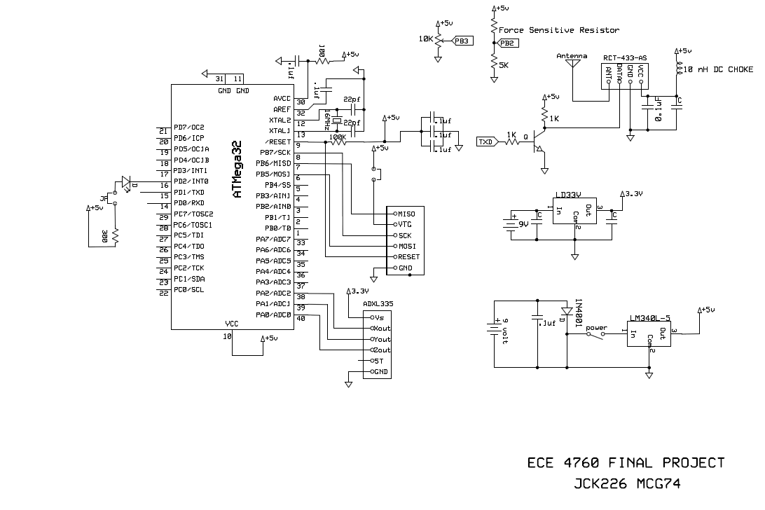
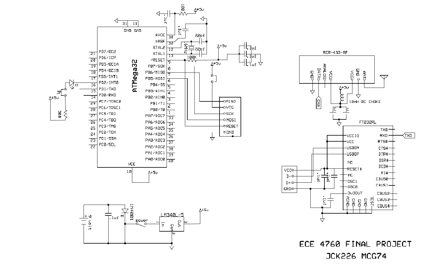
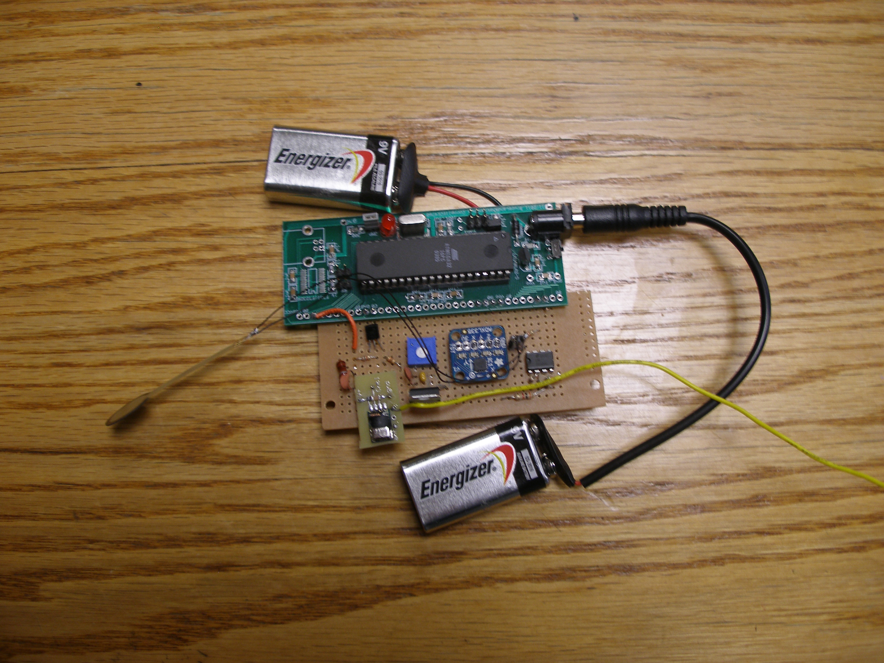
Receiver on the PC side
Transmitter with various sensor(out of the glove)
Appendix with cost
details with
all part numbers, vendors, and their price
|
Component |
Vendor |
Units |
Cost
Per Unit |
Total
Cost |
|
ATMEGA32 |
Bruce
Land |
2 |
$1
|
$2
|
|
Custom
PC Board |
Bruce
Land |
2 |
$4
|
$8
|
|
9
Volt Battery |
3 |
$2
|
$6
|
|
|
Transmitter
RCT-433 |
Bruce
Land |
1 |
$4
|
$4
|
|
Receiver
RCR-433 |
Bruce
Land |
1 |
$4
|
$4
|
|
DIP
Socket |
Bruce
Land |
2 |
$0.50
|
$1
|
|
FTDI
chip and USB connector |
Bruce
Land |
1 |
$8.00
|
$8.00
|
|
Solder
Board |
Bruce
Land |
1 |
$2.50
|
$2.50
|
|
Gloves |
1 |
FREE |
FREE |
|
|
3V
Regulator |
Sparkfun |
1 |
$1.95
|
$1.95
|
|
Header
Pins |
Bruce
Land |
40 |
$0.10
|
$4.00
|
|
Force
Sensor |
AdaFruit
Industries |
1 |
$7.00
|
$7.00
|
|
ADXL335
with breakout board |
AdaFruit
Industries |
1 |
$20.00
|
$20.00
|
|
9V
to Barrel Jack Converter |
2 |
FREE |
FREE |
|
|
9V
connector |
1 |
FREE |
FREE |
|
|
$68.45
TOTAL |
The 9V battery
converters and
connectors came from Justin, who had a couple of them lying around for
miscellaneous projects.
Appendix
Tasks carried out by each member
Hardware selection- Justin KuoReferences
Quadrotor Codebase
http://www.cs.cornell.edu/Courses/cs4758/2011sp/materials/ardrone_codebase_r10.zip
Datasheet links
http://instruct1.cit.cornell.edu//courses/eceprojectsland/STUDENTPROJ/2005to2006/mpd25/report.html
Link to FCC standards
http://www.fcc.gov/Bureaus/Engineering_Technology/Documents/bulletins/oet63/oet63rev.pdf
Code