TI Calculator Wireless Chat
Will Bruey & Michael Boor
wpb35, mdb236

REFERENCES:
Radiotronix Radio Module: http://www.radiotronix.com/products/proddb.asp?ProdID=140
*A Special Thank You to Radiotronix for the radio donations!!!*
Mega644 Protoboard: http://people.ece.cornell.edu/land/PROJECTS/ProtoBoard476/
Chat Programs: http://www.ticalc.org/archives/files/
UART SubCode: http://people.ece.cornell.edu/land/courses/ece4760/labs/s2011/lab1code/uart.c
INTRODUCTION:
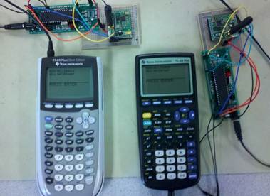
Our project is a wireless communication link which interfaces to the serial ports on the TI-83 and TI-84 calculators.
SUMMARY:
Our group created a wireless communication system for the widely popular TI 83/84 calculators. The system interfaces to each calculator through their 2.5mm serial ports. Using an instant messaging chat program written in TI Basic, and loaded onto all participating parties’ calculators, a user will be able to transmit messages over a wireless network. This device allows for convenient communication between localized parties by utilizing readily available and distributed devices. Our project models the TI calculator low level communication protocol over a wireless communication link as shown in Figure 1.
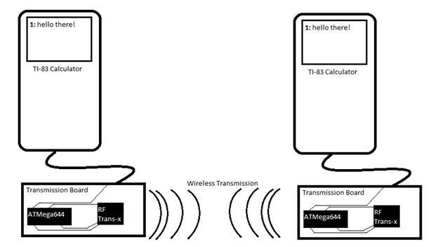
Figure 1: High Level Wireless Link Schematic
RATIONALE AND SOURCES OF PROJECT IDEA:
Mike Boor was a huge nerd in high school and spent the majority of his time trying to make his TI 83 calculator “cool”. He had an idea to make a wireless transmitter so he could communicate with his peers without the obvious serial cable link. Not possessing the skills to design such a device, he decided to become an electrical engineer. After 4 years his ignorance had disappeared but his nerdyness remained. It was time to make his dream a reality.
BACKGROUND MATH:
A small amount of mathematical formulas apply to this project, with the majority of the math present revolving around timing and logic. The serial link between calculators uses a handshake method between two signal lines which eliminates the need for a system clock to regulate data communication. This handshake protocol must execute at a minimum rate of about 200 baud or else communication will fail due to the transmitting calculator timing out while waiting for a response from the receiving calculator.
LOGICAL STRUCTURE:
The logical structure of our project came from modeling the TI serial link low level protocol. Three wires are inside a Texas Instruments Calculator serial link: Two signal lines and a reference (ground) line. The two lines go low and high according to a handshake shown in Figure 2 below. The two wires (red and white) have their High/Low (H/L) status shown at each point in the handshake in Figure 2.
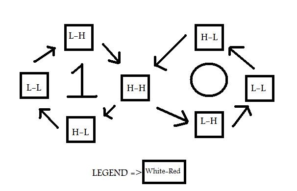
Figure 2: TI Low Level Handshaking Protocol
When the transmitting calculator wants to send a “1” to the receiving calculator, it pulls the red wire low, as shown in bottom left hand box of Figure 2. The receiving calculator responds by pulling the white wire low to achieve the left “L-L” state. Next, the transmitting calculator pulls the red wire back high, and waits for the receiving calculator to pull the white wire back high to return to the neutral state of both wires being high as shown in the middle of the figure 8 shaped diagram. When the transmitting calculator wants to send a “0”, it conducts a loop around the right portion of the figure 8 in the same manor. The process continues for two bytes worth of data (16 handshakes). Then, the receiving calculator sends back a checksum of the last two bytes. The beauty of this project is that the check sum is sent using the same handshaking procedure, so since we are modeling the lowest physical level of this protocol, our system does not need to account for high level routines such as checksums, header packets, etc. The microcontroller that interfaces to the calculator simulates the handshaking protocol with the calculator it is connected to. A calculator behaves no differently than if the other end of its communication link cable was attached to another calculator, and not a microcontroller. The microcontroller stores in memory the current state of the red or white wires (high or low), then transmits this state over the wireless link to another listening microcontroller. This microcontroller then replicates the red and white wire states on the link cable attached to its calculator. By replicating data transmission on the physical level only, we allow our device to work with any calculator software which operates over a physical link.
HARDWARE/SOFTWARE TRADEOFFS:
Speeding up data transfer is at the heart of our hardware/software tradeoffs. Because we are simulating a wire from one calculator to another, we send four pieces of data for each “bit” of information that needs to be sent across the wireless link in order to simulate each of the four stages of the handshake in Figure 2. And, since a char (8 bits) is the smallest portion of data that we can send over the radios we chose to use, we are sending 32 bits of data wirelessly between the two microcontrollers in Figure 1 for each bit of actual information. Although this may seem super inefficient, the advantages of this method greatly outweigh the 32x slower speed obtained.
1) Simulating the wire creates enormous code simplicity since, as mentioned before, we do not need to worry about ANY of the higher level protocol data transfer; we are simply modeling the wire that would be between the two calculators in a traditional serial link.
2) Any type of data, message, or program that has ever been developed to communicate over a TI serial link will still work on our system.
3) These are calculators that were developed over ten years ago, so the amount of data they are transferring is not that great, even for the relatively complex programs. The Atmel microcontrollers communicate over the wireless radio link at a rate of 115200 baud which is orders of magnitude faster than the calculators do over a traditional serial link. Plus, it is important to realize that although we send much more data over the wireless link, this data is not sent to each calculator. So all the extra information generated to simulate the transmission of a bit is done by the microcontrollers and sent over the radios, and is never processed by the actual calculators.
Since our software is way ahead of our project’s hardware when it comes to speed, no other tradeoffs needed to be made.
We chose to use the Radiotronix RF Module Wi.232DTS-EVM-R radios which could interface to a microcontroller over a simple UART connection. The radios could be easily configured upon power up by the microcontroller, and self-perform packetization, transmission, and error checking of data. By using these radios were able to treat packets sent over the UART as if the UART ports of two microcontrollers were physically linked together. This greatly increased the simplicity of our project. The radios have an unobstructed communication distance of about 1 mile.
RELVEANT TRADEMARKS/PATENTS/COPYRIGHTS:
To demonstrate our capabilities, we utilized previously developed chat software that was designed to communicate over the serial link of two wired calculators. We used TI-83 Instant Messenger II developed by MJS2000 inc, and made available on TIcalc.org. We were able to successfully run this software on our wireless link without ANY modifications to the software or calculators. The handshake protocol we modeled was developed by Texas Instruments, and the radio transceivers were developed by Radiotronix. Atmel developed our microcontrollers and we drew from UART communication code developed by Jeorg Wunsch.
PROGRAM DETAILS / TRICKY PARTS:
Two tricky parts of our code were difficult to develop. First, we needed to write code that could both receive and transmit data. The software for each microcontroller (both receiving and transmitting) is identical. Thus, the software needs to be able to know when to listen and when to speak to the radios. We did this by having the microcontroller simultaneously listen for a change in wire state initialized by the calculator, as well as if a new packet containing an updated wire states had been received through the UART via the radios. If a signal line attached to the calculator was sensed to go low as shown in figure 2, then the microcontroller would send this new state of the wires over the wireless link to the receiving calculator’s microcontroller. The receiving calculator’s microcontroller would then create this signal wire status on the receiving end. The receiving calculator then senses this change in wire status and then changes the wire status itself to move to the next part of the handshake in figure 2. The microcontroller then notices this change and reports it to the microcontroller via the wireless link and the process repeats every time a calculators changes the status of the signal lines.
The second tricky part of our code was writing to the data registers of the radios. In their normal setting, the radios are not ideal. They transmit and receive on the same default frequencies as everyone else using the radios, creating interference. The radios transmit speed is also at too low a rate by default. We needed to increase their baud rate in order for the microcontrollers to be able to communicate fast enough before the calculator handshake protocol timed out. We also configured the radio buffer size and speed to meet our needs. In addition, we wrote to some other radio registers in order to bump up the power output of the antenna for maximum transmission distance.
During transmission, the calculators transmit data via a handshake discussed in the previous sections. This means that for every bit sent, the transmitting calculator waits for a response from the receiving calculator and vice versa. If for some reason a response is never obtained, the project would be caught in an infinite loop waiting for a response from the opposing calculator. This must be avoided. If for some reason a calculator transmission fails (i.e. if it takes more than three seconds for a calculator to respond) then a watchdog timer kicks in to bail the software out of any infinite loops. Every time in the code where a calculator is waiting for a response from its counterpart, a millisecond timer counts down from three seconds. If the counter reaches zero, the transmission is aborted and the watchdog becomes active. When active, the watchdog aborts the transmission, resets the radios, signals to the calculators that the transmission failed, and then waits for a few seconds to allow the calculators to abort transmission themselves. Then, once the calculators have aborted, the radios and ports of the microcontroller are reset in preparation for another transmission attempt. The watchdog timer is needed if transmission fails due to distance, power failure, or cable disconnection.
SPEED OF EXECUTION:
The wireless link is slower than the wired serial link as discussed earlier. The net information transmission rate from one calculator to another is approximately 100 baud. This net rate includes checksums and all other protocol needs, but purely describes the information transfer rate. The wireless transmitter device (the microcontroller and radio) takes 6 seconds to load after being turned on. This load time accounts for writing to the registers, setting up a link to the other microcontroller, and establishing a steady wire state with the adjacent calculator. After this initial load time, no other overhead time is required except for a radio reset that may occur if a transmission failed for some reason (the other calculator lost power, went out of range, etc.) If such a failed transmission occurs, the radios reset and the microcontroller attempts to re-establish a stable link. This takes about 10 seconds.
ACCURACY:
As discussed earlier, the data communication protocol of a Texas Instrument calculator is a clock-less handshake over two lines. After each two bytes are sent, the receiving calculator responds with a checksum. Since our project is fooling the calculators into thinking there is a regular serial cable between them, our project is as accurate as the TI data transfer is. If there is ever a failed transmission, a breaking of the handshake, or an incorrect checksum, the calculators automatically try to resend the last two byte packet. If the transmission continues to fail and the calculator’s time out, and the radios reset as mentioned above and the system is reset. The only known reason for this is when the range of transmission nears the maximum distance and the radios begin to fail to communicate with each other.
SAFETY:
The highest voltage created on our project is 9 volts from the battery in the portable version of our device. The leads of the battery are covered and are not exposed. All electronic components are covered to reduce burning hazards if a short occurred. In addition, our project contains no choking hazards for little kids.
INTERFEARING WITH OTHER PROJECTS:
Our project uses radios that are also being used in other projects. We have communicated with them (both intentionally and unintentionally with the radios) and have come to an agreement to use different channels for each of our projects. We are the only project that uses “channel three” of the radios. The radios have slightly different central carrier frequency options which can be chosen by writing to their local registers, which we do every time the project is turned on or reset.
USABILITY:
The project is very easy to use by anyone. There is only one button: the ON switch. The project then automatically acts as a serial link between the calculators. Using the project requires no additional knowledge than is required to link two TI calculators with a conventional, Texas Instruments provided serial link. Plug and Play Baby!
EXPECTATIONS MET? :
Our radios work just as we had hoped. However, the wireless link is slower than a direct wire link. This is due to the radios being the bottleneck and transferring more data than is needed (char instead of single bit). However, this added time is minor. If we were to do this again, we may be able to figure out a way to send a single bit of data over the radios, or possibly spend a lot of extra time recognizing a higher level of the TI protocol in order to send information by the byte instead of the bit. Either method would result in higher data transmission rate. Other than that, our project met all success criteria and specifications laid out in our initial project proposal!
CONFORMATION TO APLICABLE STANDARDS:
We used the RF Module Wi.232DTS-EVM-R by Radiotronix. This transceiver broadcasts at frequencies near 900 Mhz. This radio is declared acceptable by Title 47 CFR Part 15 Section C of FCC Regulations. We also follow the TI Low Level Protocol standard for communicating over a physical link between each microcontroller and calculator.
INTELECTUAL PROPERTY USED:
UART Code by Jeorg Wunsch TI-83 Instant Messenger II code by MJS2000 inc. Downloaded from TIcalc.org
Other than the UART Code, all other Microcontroller code was developed from scratch by us. Our design and implementation is purely our own. Our calculator to radio interfacing algorithms could potentially be of interest to others. However, since this project’s foundation is related to Texas Instrument devices, patents and publications do not seem justifiable.
ETHICAL CONSIDERATIONS:
Our project complies with all parts of the IEEE code of ethics. Our project does not create any waste other than used 9 volt batteries. A low power version is configurable for short ranged transmission to avoid wasting energy and RF noise. Carrier frequencies of the radios are low enough such that no threat is posed to the human body regardless of position with respect to the radios. We have been completely honest with regards to all intellectual material we have used from others. A comprehensive list of this material is as follows and credited in this document: UART linked code, radio transceivers, and chatting programs for demoing. We have honestly reported all specifications, limitations, and capabilities of our project in this document to the best of our knowledge and ability. We have demonstrated our project to several peers and encouraged their verbal feedback while using our product. We actively worked with and assisted our peers when learning how to operate the Radiotronix modules. We rejected all bribery from students who wanted to borrow our devices for finals week. We cannot be held responsible if students try to cheat on tests using wireless chat between TI calculators. We do not endorse such behavior. This project allowed us to improve our technical competence, while contributing to the understanding of a prominent technology.
LEGAL CONSIDERATIONS:
We used the RF Module Wi.232DTS-EVM-R by Radiotronix. This transceiver broadcasts at frequencies near 900 Mhz. This radio is declared acceptable by Title 47 CFR Part 15 Section C of FCC Regulations.
Appendix A: Microcontroller Code
/*
Texas Instrument Wireless Transmission Source Code
Developed by Will Bruey and Michael Boor
This code allows an Atmell 644 microcontroller to communicate with both
a radio and a calculator to create a wireless transmission interface
through the Texas Instrument Serial Port on TI83 and TI84 calculators.
Compiled using Win AVR on a pentium core 2 running windows 7.
*/
//Included Header Files
#include <inttypes.h>
#include <avr/io.h>
#include <avr/interrupt.h>
#include <stdio.h>
#include <math.h>
#include <avr/pgmspace.h>
#include <stdlib.h>
#include <string.h>
#include "uart.h"
#include <util/delay.h>
#define red 0b00000010 //port that controls red serial signal wire
#define white 0b00000001 //port that controls white serial signal wire
#define D_lay _delay_us(1) //small, inacurate delay, to allow voltages to settle
#define power 0b00000001 //pin that controls base of power bjt
#define ctl 0b00000010 //pin that controls binary cntl input for radio
#define radioTimeout 3000 //miliseconds
volatile char watchDogMad=0;//this is true if watchdogtimer has timed out
volatile int counter=0; //counter for watch dog timer.
FILE uart_str = FDEV_SETUP_STREAM(uart_putchar, uart_getchar, _FDEV_SETUP_RW);
//milisecond counter from timer 0
ISR (TIMER0_COMPA_vect){
//Decrement the time if not already zero
if (counter>0){counter=counter-1;}
}
//this fucntion recieves a uart message to the microcontroller
unsigned char USART_Receive( void )
{
/* Wait for data to be received */
while ( !(UCSR0A & (1<<RXC0)) );
/* Get and return received data from buffer */
return UDR0;
}
//clears the UART buffer in microcontroller
void clearBuffer(void){
unsigned char dummy=0;
while ( UCSR0A & (1<<RXC0) ) dummy = UDR0;
}
//this subfunction resets the radios
void resetRadio(void){
_delay_ms(1000);
//set microcontroller to 2400 baud UART
UBRR0L= 160;
UBRR0H = 1;
UCSR0B = _BV(TXEN0) | _BV(RXEN0); /* tx/rx enable */
//turn off power to radios
DDRB=0b00000111;
PORTB=0b00000100;
PORTB|=power; //turn on power
PORTB|=ctl; //turn ctl HIGH
_delay_ms(1000);
PORTB&=~ctl; //turn CTL low
PORTB&=~power; //turn off power
_delay_ms(1000);
PORTB|=power; //turn on power
_delay_ms(1000);
//change data rate
unsigned char header1 = 0xFF;
unsigned char size1 = 0x02;
unsigned char escape1 = 0x4E;
unsigned char regnum1 = 0b00000101;
//change to minimum timeout
unsigned char header2 = 0xFF;
unsigned char size2 = 0x02;
unsigned char escape2 = 0x50;
unsigned char regnum2 = 0b00000001; //full buffer requiered
//change to buffer size to 1 byte
unsigned char header3 = 0xFF;
unsigned char size3 = 0x02;
unsigned char escape3 = 0x54;
unsigned char regnum3 = 0b00000001; //go after 1 byte recieved
//change change power mode
unsigned char header4 = 0xFF;
unsigned char size4 = 0x02;
unsigned char escape4 = 0x4D;
unsigned char regnum4 = 0b00000011;
//change channel to channel 3
unsigned char header5 = 0xFF;
unsigned char size5 = 0x02;
unsigned char escape5 = 0x4B;
unsigned char regnum5 = 0b00000011; //go after 1 byte recieved
unsigned char header6 = 0xFF;
unsigned char size6 = 0x02;
unsigned char escape6 = 0x4C;
unsigned char regnum6 = 0b00000011; //go after 1 byte recieved
//change channel to channel 3
uart_putchar(header5, &uart_str);
uart_putchar(size5, &uart_str);
uart_putchar(escape5, &uart_str);
uart_putchar(regnum5, &uart_str);
uart_putchar(header6, &uart_str);
uart_putchar(size6, &uart_str);
uart_putchar(escape6, &uart_str);
uart_putchar(regnum6, &uart_str);
//change change power mode
uart_putchar(header4, &uart_str);
uart_putchar(size4, &uart_str);
uart_putchar(escape4, &uart_str);
uart_putchar(regnum4, &uart_str);
//change to minimum timeout
uart_putchar(header2, &uart_str);
uart_putchar(size2, &uart_str);
uart_putchar(escape2, &uart_str);
uart_putchar(regnum2, &uart_str);
//change to buffer size to 1 byte
uart_putchar(header3, &uart_str);
uart_putchar(size3, &uart_str);
uart_putchar(escape3, &uart_str);
uart_putchar(regnum3, &uart_str);
//change data rate
uart_putchar(header1, &uart_str);
uart_putchar(size1, &uart_str);
uart_putchar(escape1, &uart_str);
uart_putchar(regnum1, &uart_str);
_delay_ms(100);
PORTB|=ctl; //turn control high
//FOR 115200baud
UBRR0L = 8;
UBRR0H= 0;
UCSR0B = _BV(TXEN0) | _BV(RXEN0); /* tx/rx enable */
_delay_ms(1000);
}
int main(){
//make port B outputs
DDRB=0b00000111;
//set up timer 0 for 1 mSec timebase
TIMSK0= (1<<OCIE0A); //turn on timer 0 cmp match ISR
OCR0A = 249; //set the compare re to 250 time ticks
//set prescalar to divide by 64
TCCR0B= 3; //0b00001011;
// turn on clear-on-match
TCCR0A= (1<<WGM01) ;
//uart setup
uart_init();
stdout = stdin = stderr = &uart_str;
//declare wire settings
const char WHRH= 0b00110000; //0 ascii, 48 decimal
const char WHRL= 0b00110001; //1 asxii
const char WLRH= 0b00110010; //2 ascii
const char WLRL= 0b00110011; //3 ascii
char RX= 0b11111111; //4 ascii
resetRadio();
clearBuffer();
DDRA=0b11111111; //port A outputs
PORTA=0b00000000; //set all pin defaults to gound.
DDRA=0b11111100; //all outputs except two listen pins
PORTA=0b00000000; //pullup resistors off ground non used pins
_delay_us(5); // Let defaults settle
PORTB|=0b00000100; //set port high for light make blinky blink
//turn on ISRs
sei();
while(1){
//if the watchdog has triggered, do the following
if(watchDogMad==1){
//turn on the pullup resistors
PORTA|=0b00000111;
_delay_ms(1000);
//flash the LED
PORTB|=0b00000100;
//reset the radios, watchdogtimer, and watchdog flag
resetRadio();
counter=0;
watchDogMad=0;
_delay_ms(500);
//blink the LEDs
PORTB^=0b00000100;
_delay_ms(500);
PORTB^=0b00000100;
_delay_ms(500);
PORTB^=0b00000100;
_delay_ms(500);
//turn the pullup resistors back off
PORTA&=0b11111000;
//flash the LEDs
PORTB^=0b00000100;
_delay_ms(100);
PORTB^=0b00000100;
_delay_ms(100);
PORTB^=0b00000100;
_delay_ms(100);
PORTB^=0b00000100;
_delay_ms(100);
PORTB^=0b00000100;
_delay_ms(100);
PORTB^=0b00000100;
_delay_ms(100);
PORTB^=0b00000100;
_delay_ms(100);
PORTB^=0b00000100;
_delay_ms(100);
}
PORTB^=0b00000100; //blink light during data transmission
// CALCULATOR ON PORT A///////////////////////////////////////////////////////////////////
if(!(PINA&white)){//if the white pin on Port A goes low
D_lay; //wait 1 miliseconds
fprintf(stdout,"%c", WLRH); // Transmit line state to other calc
counter=radioTimeout;
while( !(RX==WLRL) && !watchDogMad) { // Wait for other calc to pull Red low
if(1==counter){
watchDogMad=1;
}
if ((UCSR0A & 0x80)){
RX=USART_Receive();
clearBuffer();
}
}
counter=0;
DDRA^=red; //make the red pin on Port A an output
D_lay; //wait 1 miliseconds
PORTA&=~red; //make red pin on Port A go low
D_lay; //NEW_DELAY
counter=radioTimeout;
while(!(PINA&white) && !watchDogMad) { // Wait for calc on Port A to pull White High
if(1==counter){
watchDogMad=1;
}
D_lay;
}
counter=0;
fprintf(stdout,"%c", WHRL); // Transmit line state to other calc
counter=radioTimeout;
while(!(RX==WHRH)&& !watchDogMad) { // Wait for other calc to pull Red High
if(1==counter){
watchDogMad=1;
}
if ((UCSR0A & 0x80)){
RX=USART_Receive();
clearBuffer();
}
}
counter=0;
D_lay;
PORTA^=red; //make red pin on Port A go high
D_lay;
DDRA=0b11111100;//go back to listening to the two pins on Port A
RX= 0b11111111;
D_lay;
}
if(!(PINA&red)){//if the Red pin on Port A goes low
D_lay; //wait 1 miliseconds
fprintf(stdout,"%c", WHRL); // Transmit line state to other calc
counter=radioTimeout;
while( !(RX==WLRL)&& !watchDogMad) { // Wait for other calc to pull White low
if(1==counter){
watchDogMad=1;
}
if ((UCSR0A & 0x80)){
RX=USART_Receive();
clearBuffer();
}
}
counter=0;
DDRA^=white; //make the White pin on Port A an output
D_lay; //wait 1 miliseconds
PORTA&=~white; //make White pin on Port A go low
counter=radioTimeout;
while( (!(PINA&red))&& !watchDogMad) { // Wait for calc on Port A to pull Red High
D_lay;
if(1==counter){
watchDogMad=1;
}
}
counter=0;
fprintf(stdout,"%c", WLRH); // Transmit line state to other calc
counter=radioTimeout;
while(!(RX==WHRH)&& !watchDogMad) { // Wait for other calc to pull White High
if(1==counter){
watchDogMad=1;
}
if ((UCSR0A & 0x80)){
RX=USART_Receive();
clearBuffer();
}
}
counter=0;
D_lay;
PORTA^=white; //make White pin on Port A go high
D_lay;
DDRA=0b11111100;//go back to listening to the two pins on Port A
RX= 0b11111111;
D_lay;
}
if ((UCSR0A & 0x80)){
RX=USART_Receive();
fprintf(stdout,"%c\n",RX);
clearBuffer();
}
if (RX==WLRH){
DDRA^=white; //make the white pin on Port A an output
D_lay; //wait 1 miliseconds
PORTA&=~white; //make white pin on Port A go low
D_lay; //NEW_DELAY
counter=radioTimeout;
while( ((PINA&red)) && !watchDogMad) { // Wait for calc on Port A to pull Red low
D_lay;
if(1==counter){
watchDogMad=1;
}
}
counter=0;
fprintf(stdout,"%c", WLRL); // Transmit line state to other calc
counter=radioTimeout;
while(!(RX==WHRL)&& !watchDogMad) { // Wait for other calc to pull White High
if(1==counter){
watchDogMad=1;
}
if ((UCSR0A & 0x80)){
RX=USART_Receive();
clearBuffer();
}
}
counter=0;
PORTA^=white; //make white pin on Port A go High
counter=radioTimeout;
while( (!(PINA&red)) && !watchDogMad) { // Wait for calc on Port A to pull Red High
if(1==counter){
watchDogMad=1;
}
D_lay;
}
counter=0;
D_lay;
fprintf(stdout,"%c", WHRH); // Transmit line state to other calc
D_lay;
DDRA=0b11111100;//go back to listening to the two pins on Port A
RX= 0b11111111;
D_lay;
}
if (RX==WHRL){
DDRA^=red; //make the red pin on Port A an output
D_lay; //wait 1 miliseconds
PORTA&=~red; //make red pin on Port A go low
D_lay; //NEW_DELAY
counter=radioTimeout;
while( ((PINA&white))&& !watchDogMad ) { // Wait for calc on Port A to pull White low
if(1==counter){
watchDogMad=1;
}
D_lay;
}
counter=0;
fprintf(stdout,"%c", WLRL); // Transmit line state to other calc
counter=radioTimeout;
while(!(RX==WLRH)&& !watchDogMad) { // Wait for other calc to pull Red High
if(1==counter){
watchDogMad=1;
}
if ((UCSR0A & 0x80)){
RX=USART_Receive();
clearBuffer();
}
}
counter=0;
PORTA^=red; //make red pin on Port A go High
counter=radioTimeout;
while( (!(PINA&white)&& !watchDogMad) ) { // Wait for calc on Port A to pull White High
if(1==counter){
watchDogMad=1;
}
D_lay;
}
counter=0;
D_lay;
fprintf(stdout,"%c", WHRH); // Transmit line state to other calc
D_lay;
DDRA=0b11111100;//go back to listening to the two pins on Port A
RX= 0b11111111;
D_lay;
}
}//end while
}//end main
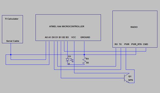
APPENDIX B: DEVICE SCHEMATIC
Complete Device Schematic
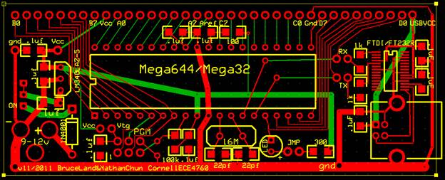
Mega644 Protoboard
Radiotronix RK-Wi.232DTS
|
Pin Name |
Pin Description |
|
JP2 Pin 1 |
4V to 12V Vdd |
|
JP2 Pin 2 |
RxD0 |
|
JP2 Pin 3 |
TxD0 |
|
JP2 Pin 4 |
CTS0 |
|
JP2 Pin 5 |
CMD (Active Low) |
|
JP2 Pin 6 |
RxD1 – Reserved for Future – No Connect |
|
JP2 Pin 7 |
TxD1 – Reserved for Future – No Connect |
|
JP2 Pin 8 |
RTS1 – Reserved for Future – No Connect |
|
JP2 Pin 9 |
DTR1 – Reserved for Future – No Connect |
|
JP2 Pin 10 |
DTR1* - Reserved for Future – No Connect |
|
JP2 Pin 11 |
GND |
|
JP2 Pin 12 |
GND |
|
JP1 Pin 1 |
GND |
|
JP1 Pin 2 |
GND |
|
JP1 Pin 3 |
AD1 – Reserved for Future – No Connect |
|
JP1 Pin 4 |
AD0 – Reserved for Future – No Connect |
|
JP1 Pin 5 |
RSSI – Reserved for Future – No Connect |
|
JP1 Pin 6 |
PD5 – Reserved for Future – No Connect |
|
JP1 Pin 7 |
PD4 – Reserved for Future – No Connect |
|
JP1 Pin 8 |
PD3 – Reserved for Future – No Connect |
|
JP1 Pin 9 |
PD2 – Reserved for Future – No Connect |
|
JP1 Pin 10 |
PD1 – Reserved for Future – No Connect |
|
JP1 Pin 11 |
GND |
APPENDIX C: COST LIST
|
Part |
Quantity |
Unit Cost |
Total Cost |
Vendor |
|
Atmel Mega644 Microcontroller |
2 |
$8.00 |
$16.00 |
Bruce Land |
|
Radio-frequency Transceiver RF Module Wi.232DTS-EVM-R |
2 |
Free (Donation) |
$0.00 |
Radiotronix |
|
Power Supply |
2 |
$5.00 |
$10.00 |
Bruce Land |
|
Custom PC Board |
2 |
$4.00 |
$8.00 |
Bruce Land |
|
Solder Board (2 inch) |
2 |
$1.00 |
$2.00 |
Bruce Land |
|
2.5mm jack and Cable |
1 |
$1.00 |
$1.00 |
Amazon.com |
|
NPN Transistor |
2 |
Free |
Free |
Bruce Land |
|
Pins |
40 |
$0.05 |
$2.00 |
Bruce Land |
|
Total Cost: |
$39.00 |
|||
APPENDIX D: SPECIFIC TASKS
Will Bruey Tasks:
· Wrote radio configuration code.
· Wrote watchdog code.
· Wrote major portion of final write up.
· Designed radio power/control technique.
Michael Boor Tasks:
· Came up with idea.
· Bought supplies.
· Built proto boards.
· Planned labs.
· Wrote code to execute handshake.
· Built radio boards.