
Introduction
We created a system that takes input from a piano and displays the musical notation for it on a television screen.
The system uses hardware amplification and filtering of a microphone output with code in C compiled on two Atmel Mega644 microcontrollers.
The basic tasks required are pitch identification, measurement of note duration, and video generation. We chose this project because both of us play
(or have played) musical instruments and know how frustrating it can be to write out sheet music, whether by hand or using a computer program.
We felt that this Sheet Music Notator could be a useful tool for beginning musicians and composers.
High Level Description
Rationale and Sources
We wanted to choose a project that could be both useful for a large group of people and rewarding to design and build. As previously mentioned, we are both musicians, so one of the first things that came to mind when we started brainstorming final project ideas was tools for musicians. We were both surprised that such a tool was not already widely used (in fact, we only found one such program on the market, and that, too, after a long search), so we decided to build it.
Logical Structure
We chose to take input from a keyboard specifically because it outputs a synthesized sound and will have clearer frequencies than human-produced sound (though we found that this instrument is actually far from an ideal synthesizer).
The notator consists of the following subsystems: a microphone and preamp stage, a filter stage, a note detection stage, a video driver stage, and then a display stage, arranged as shown in Fig. pi below.
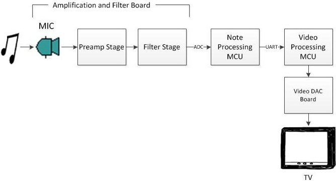
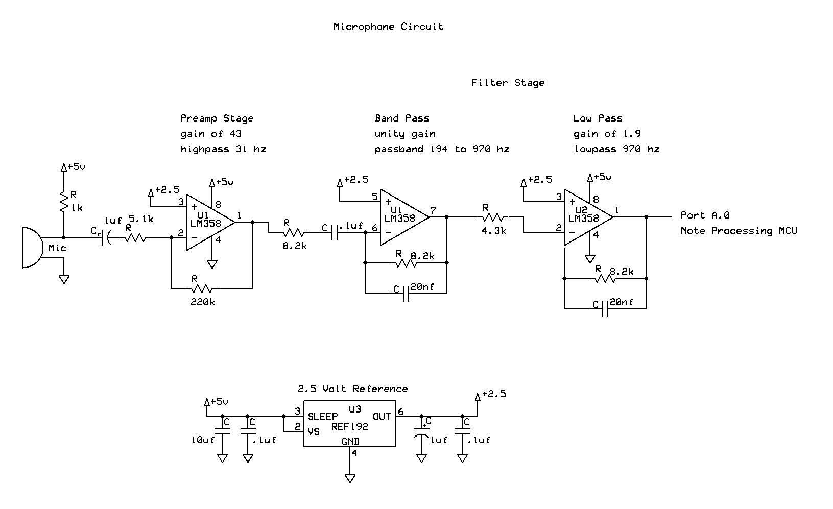
We input the sound from the piano to our system through a microphone. This way, any sound source could theoretically be used with our system, though our program has it tuned for the Casio keyboard we will be using to demo, and calibration for other instruments is outside of the scope of our project. The microphone signal is fed into a preamp stage designed to get the signal to a level that can be read by our ADC. It also has a high pass filter/DC block so that we can center the signal around a frequency of our choice and remove some low frequency noise.
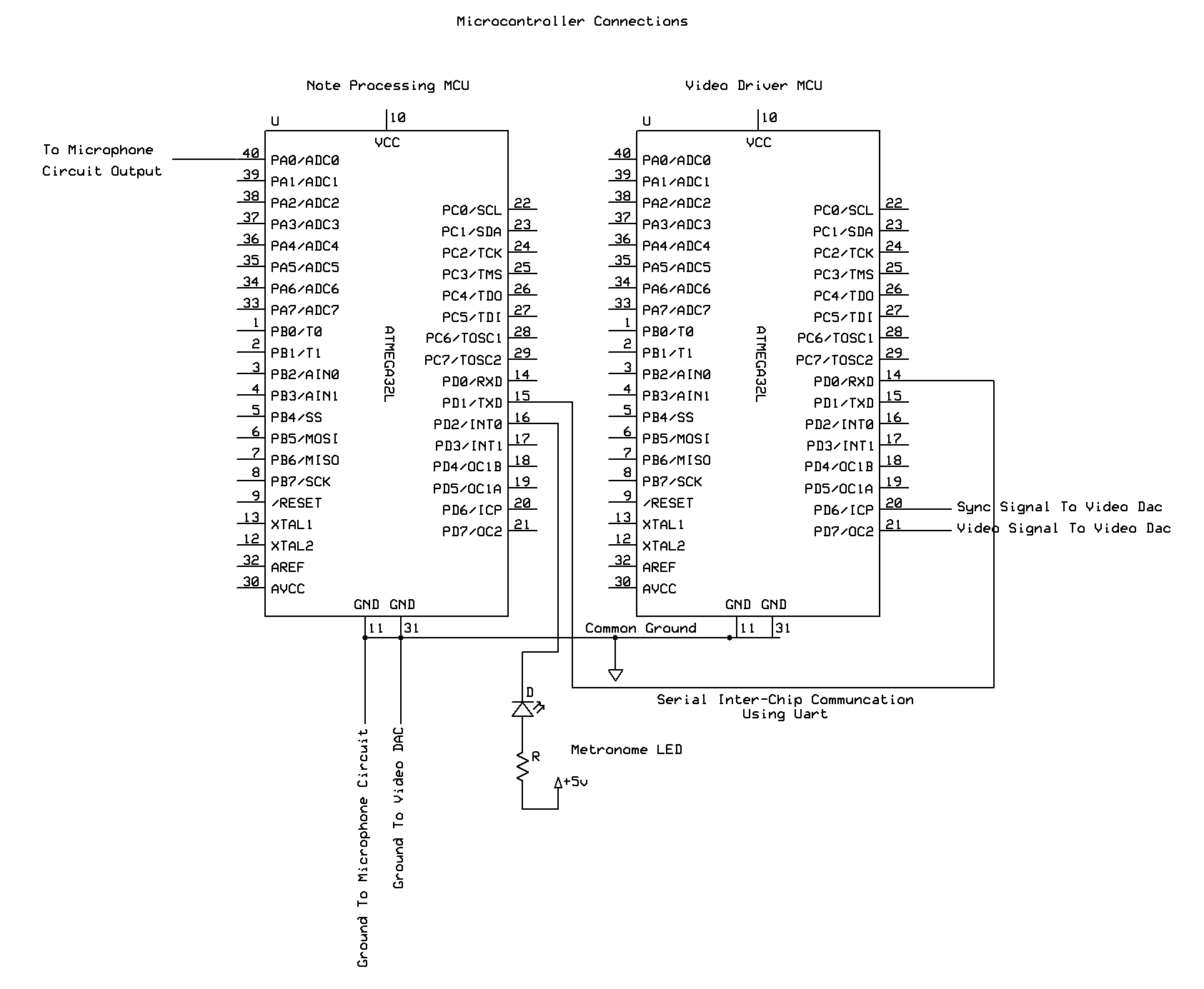
After the preamp stage is a filter stage where all frequency components not in our note range will be filtered out. One of the filter stages also adds gain to give us more resolution. The microphone, preamp, and filter stages are all on one breadboard, called the filtering and amplification board in Fig. pi above. The filtered and amplified signal is read by the ADC of an AtMega644 microcontroller, which detects note pitches and lengths using the note detection methods described in the background math section below. It then sends this information to the video processing MCU using a serial connection.
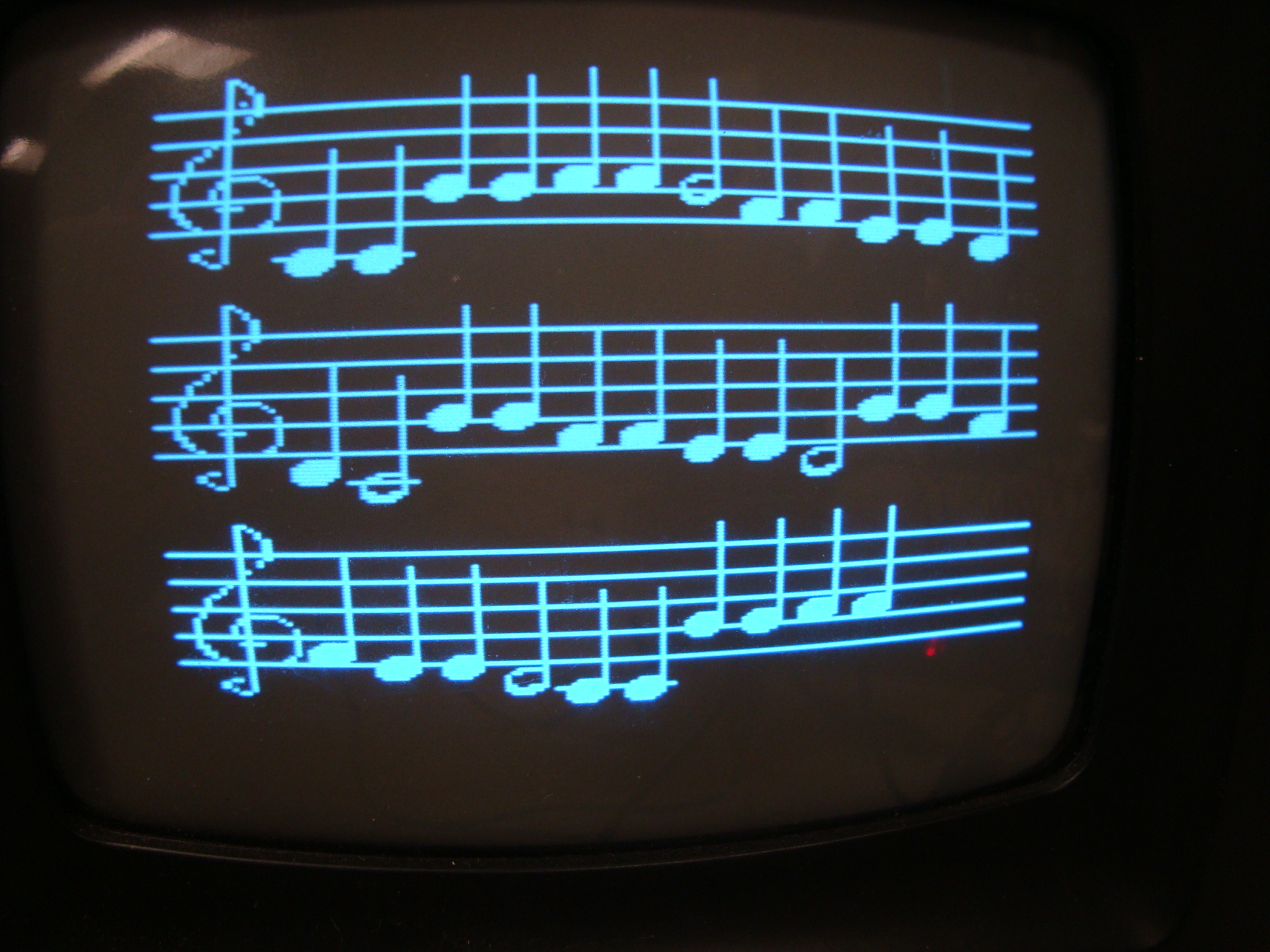
The video processing MCU takes the length and pitch information for each new note and converts it into a picture drawn onto a black and white television using the NTSC protocol. Notes are correctly displayed on a staff in the sequence they were played. For example, Fig. 2 below shows the output after someone has finished playing "Twinkle, Twinkle Little Star". This MCU is connected to the TV itself using the same circuit that was used in Lab 3.
Verify this here.
We use two MCUs because both FFT and video are fairly memory-intensive operations and simply cannot be implemented on the same chip.
Background Math
Pitch Determination
A fast Fourier transform (FFT) is used to determine the pitch, or frequency, of each note. A Fourier transform takes a signal that is in the time domain and transforms it to the frequency domain, and an FFT is any algorithm which quickly calculates a discrete Fourier transform, i.e. one in which the input time domain signal and the output frequency domain signal are both discrete.
To take an FFT of continuous time piano music, the FFT algorithm first samples the data to generate the input signal, using the ADC on the microcontroller to get input from the microphone. It takes the real and imaginary components of the signal at discrete time intervals and outputs a one pair of real and imaginary amplitude components corresponding to each sampled frequency. The output frequencies are evenly spaced from 0 to the Nyquist rate (half the sampling rate), so n samples taken at m Hz yields n/2 discrete frequencies starting at 0 and incrementing by 2m/n Hz.
We chose to use a 2 kHz sampling rate with 128 samples for the fft, giving a frequency spacing of 15.625 Hz. Starting at A bellow middle C (A3), notes on a piano are all at least 13 Hz apart, and spacing increases with pitch. The sampling rate set our highest note at A5, which is just below m/2, or 1kHz. With the discrete frequencies for which amplitudes are sampled in this system, no two note frequencies are closest to the same discrete frequency. There is now an injective mapping from piano notes to discrete frequencies from the transform, so every note between A3 and A5 can be detected using this algorithm.
After completing the FFT, we have a vector set of complex amplitudes. Normally, to determine the magnitude of the signal at each frequency, one would take the square root of the sums of the squares of the real and imaginary parts: |H(w)| = sqrt[ (real)^2 + (imaginary)^2]. However, squaring and square rooting are both time-consuming operations, so we simplified the algorithm to only take the sum of the absolute values of the parts: |H(w)| = abs(real) + abs(imaginary). This was appropriate because we were only interested in the frequency with the highest magnitude, and not the actual value of the magnitude.
Length Determination
To determine note length, the program first determines the envelope of the audio signal by first rectifying and then low passing the signal. The filter cutoff is set well below the signal's lowest frequency component. The sine waves that make up the audio signal will then essentially be averaged so the output after the low pass will be proportional to the amplitude of the audio signal. If the signal isn't rectified the low pass will average to 0 for any amplitude, but with rectification it will average to about half the amplitude of the sine wave.
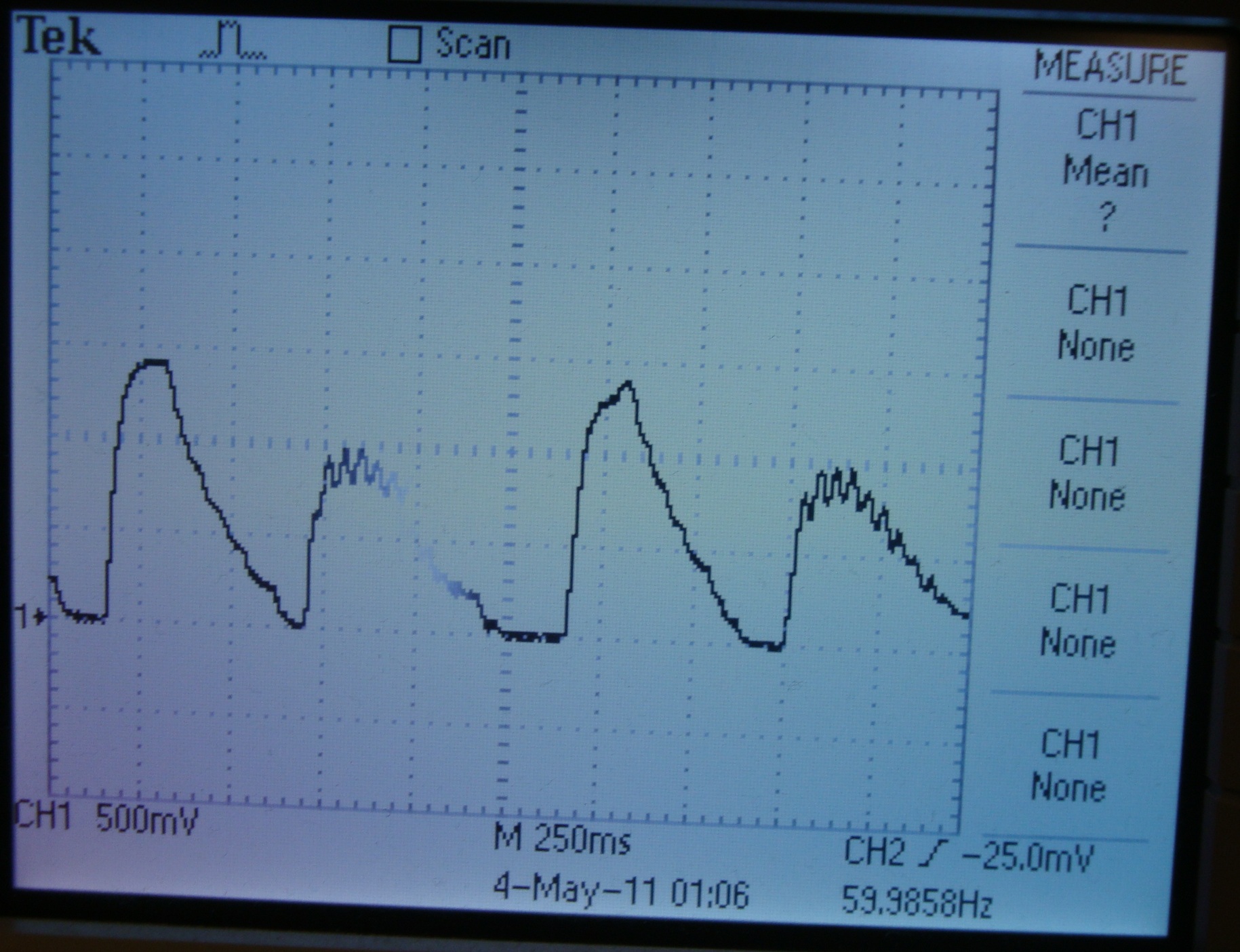
Once the envelope has been determined, an algorithm is used to detect when a new note starts. Even with as much low passing as we can afford without excessively attenuating the higher frequencies, the envelope is fairly noisy. Different frequencies have different maximum amplitudes, and a note usually hasn't decayed completely before the next is played, so a simple threshold or even a simple hysteresis loop won't work. Figure 3 below shows a shot from the oscilloscope displaying alternating notes, one with a fairly smooth envelope (E3) and one with a very noisy envelope (D4).
The algorithm we implemented detects rising and falling edges. If envelope values are rising, it keeps track of the maximum value since the previous falling edge ended by comparing new to the current maximum value. If a value is above the maximum, it sets the stored maximum to the new value. If it is between the maximum and a threshold somewhat lower than the maximum, the algorithm moves on to the next sample. If the new value is below the threshold, it then considers the signal to be on a falling edge. Falling edges are handled similarly, by checking for a minimum and some amount above the current minimum.
Using this algorithm, the time between two rising edges can be measured to get the note length. We tuned the thresholds by experimenting. If the value is too low, notes will double trigger since the noise will push the envelope beyond the threshold. But, if the threshold value is too high, then the shortest note that registers will be longer, since the time where the decay is less than the threshold will be increased, and if you play a second note before the threshold is crossed it will not register. This algorithm is thus resistant to noise, different max amplitudes for different notes, notes not fully decaying before the next note is played.
Video Generation
This part of the project required only elementary math. Two global position variables are used. The point in the x direction is incremented each time a new note is displayed. The amount of the increment depends on how much space the note displayed takes up. In general, a two-pixel pad is added between each note to make reading easier. The vertical coordinate of a note is always determined relative to the top line of the musical staff. The global y direction pointer is incremented only when one line of music fills up on the screen and we have to move to the screen.
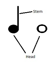
Since the pitch of a note determines the vertical coordinate for the head of the note (see Fig. 4 below for an explanation of the terms "head" and "stem"), a constant value is added to the global y coordinate for each note. Most notes have a stem that extends for 3.5 staff lines above or below the head. The whole note is an exception to this rule, but we treat the whole note as if it has an undrawn stem so that we can always use the same increment of the global y-coordinate to determine the y-coordinate for a pitch. Simple case statements sufficed for this purpose (see Software section and lab5vid.c in Appendix A).
Basic condition checking on the number of pixels used by each line allowed us to move to new lines and new scores as appropriate.
Hardware/Software Tradeoffs
We encountered several tradeoffs when designing are system. The first tradeoff we encountered was cost vs quality in the microphone and in the design in general. The more expensive the microphone the better it would perform so the quicker notes could register and the more accurate the frequency detection would be, but that would also means a more expensive end product. For a consumer device the key would be to find the cheapest microphone that would give you the performance that you desire. For us the microphone we used detected all our picthes correctly nearly 100% of the time so a more expensive microphone wouldn't have helped in that area, but it would have probably had less noise and as such we could have detected shorter notes. Noise can also be filtered out, but similarly a more robust filter requires more components and would be more expensive.
Another tradeoff was ease of simplicity of implementation vs robustness for a communication protocol. A simpler protocol has less features but is easier debug and get working. While a more complex protocol would be harder to implement but would give better performance and have more features. The key here is similar to the one with cost, to find the easiest protocol to implement that still gives all of the required features and performance. In our system we only needed to send 2 bytes at 10hz or lower and only in one direction so we used the UART to send individual characters.
Another tradeoff is hardware versus software filtering. With hardware filtering it doesn't require any additional microcontroller processing power since it is happening externally and you don't need to wait for an algorithm to finish in your code to get the filter output, but it also requires building more circuits so it ups the cost, and complexity of the hardware. Also for somethign like rectifying you need to use diodes and therefore you lose voltage to the turn on voltage of the diode. With software filtering you lose processing power, but it also doesn't take up any additional space and you can manipulate the data a lot more since you aren't bound by the physical laws of the universe like you are in a physical hardware filter. In our design we utilized both hardware and software filtering to get the best results.
Standards Implemented
Universal Asynchronous Receiver/Transmitter(UART)
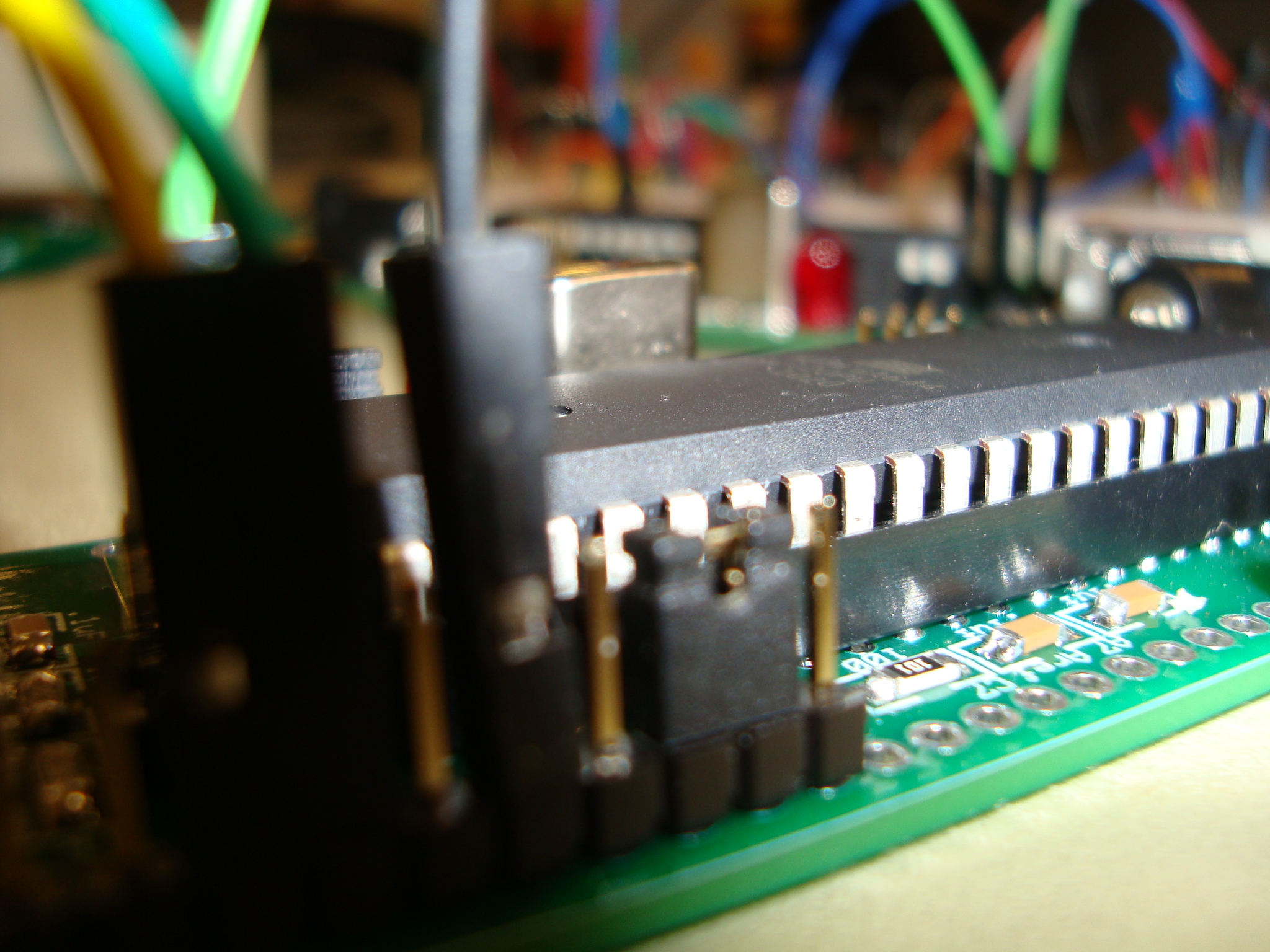
Serial communication between our two microcontroller chips is achieved using the UARTs included on the Atmega644s. A UART is a standard device for asynchronous serial communication. UARTs send the following packages: a start bit which is logic low, then a number of data bits, an optional parity bit, and one or more logic high stop bits. In our system, the UARTs are configured to use one stop bit and no parity bit. Between data packets the line is set high. Each UART has a transmit pin and a receive pin, and data is sent from the transmit pin of one UART to the receive pin of another. The lines are independent, so both MCUs can receive and transmit simultaneously, but our system requires only one-way communication. A close-up of this connection is included in the sidebar on the left.
National Television System Committee (NTSC)
For the video code, we used a variant of the NTSC standard. Frames in our system refresh at 60 Hz (i.e., each frame has exactly 1/60 of a second to be displayed) and must be synced from a known state. However, our signal is not interlaced, as standard NTSC is; we draw every line every frame rather than every other. All of the code to generate the actual signal is adapted from code provided by the ECE 4760 staff for Lab 3. There are 262 lines on the screen, but our settings for variables screentop =10 and screenbottom =190 mean only 180 lines are visible. All computation is carried out during the time in which the remaining 50 lines would be drawn. The MCU output is input to the television through a coaxial stripped coaxial cable as in Lab 3. A close-up of this connection is included in the sidebar on the left.
Relevant Patents
Initially, it seemed (to our surprise) that the Sheet Music Notator was a completely novel idea. After some thorough searching, however, we found that Akoff Music Labs' Music Composer 2.0 accomplished similar goals. However, this is a purely software implementation that uses much more complicated processes for polyphonic recognition, file type conversion and score editing. Consequently, it requires a more robust processor to function properly. We did not reference this program at all, and neither of us has ever used it.
A much more powerful version that could save the music displayed on the screen and take a variety of musical inputs could conceivably be used in place of sheet music bought from a vendor, and those who chose to use it for those purposes would be infringing copyright and royalty laws on the music. However, the technology itself does not violate those laws, and since our notator currently has no memory and is only capable of recognizing and displaying simple melodies that wouldn't be too difficult to notate by hand, it is highly unlikely that it would be used for such purposes.
System Design
Hardware
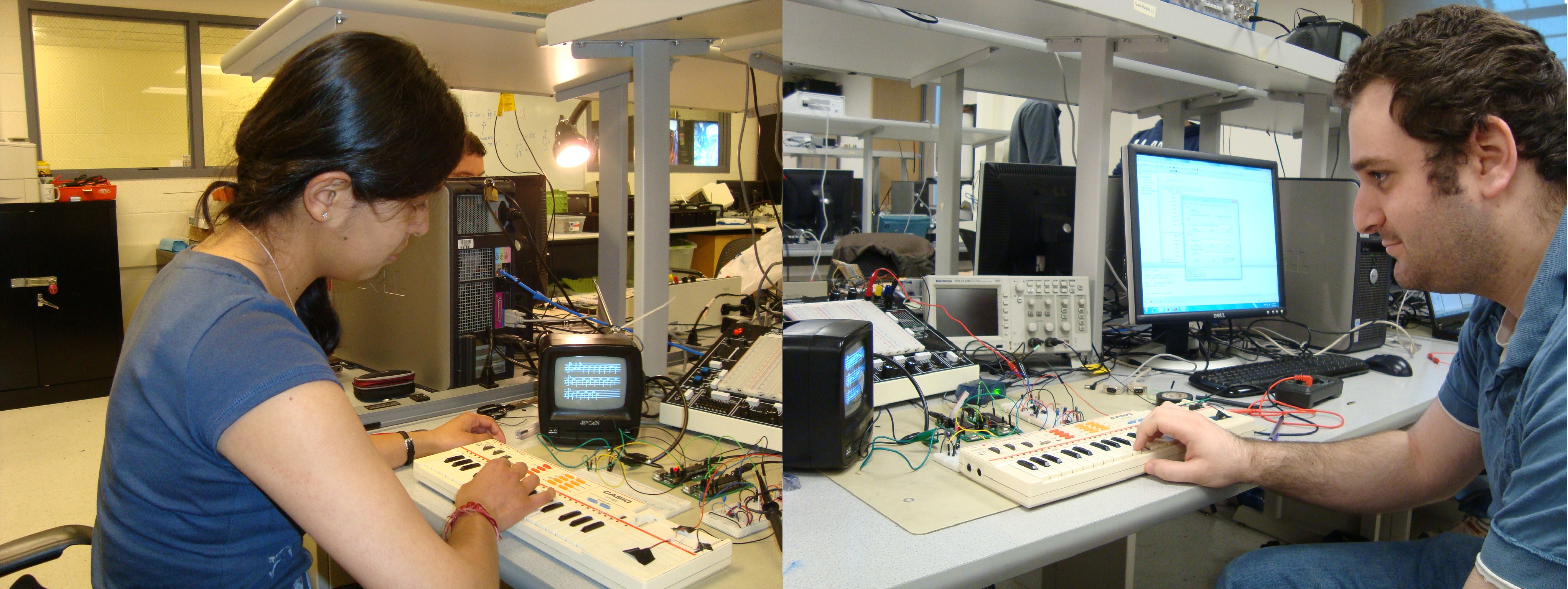
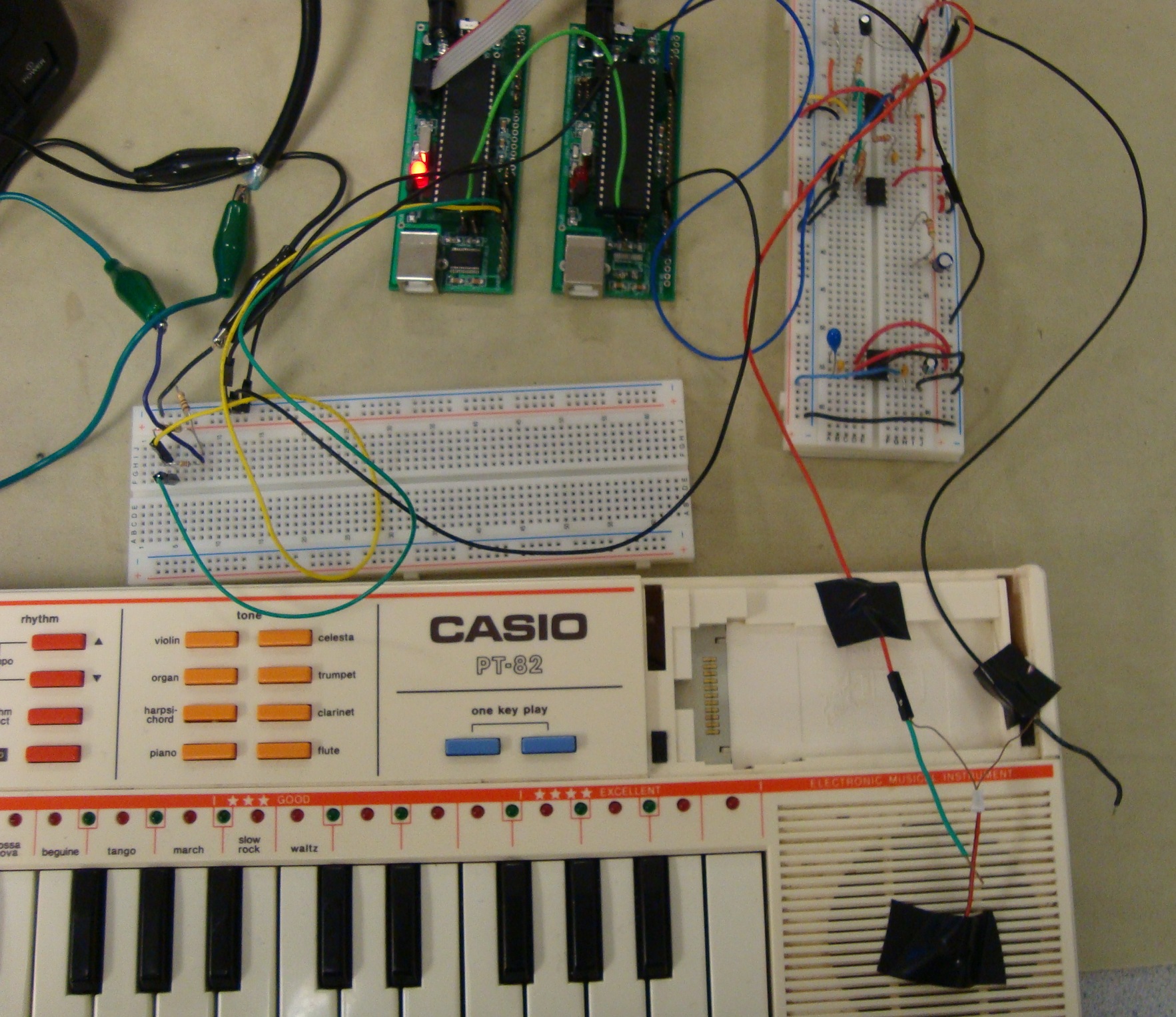
The hardware component of this lab is fairly simple and could easily be reproduced, as we used only very standard electrical components: LN358 op-amps, a 2.5 voltage reference, resistors, capacitors, wire, connector cables, alligator clips and a microphone in addition to the Mega644 boards. Figure 5 below shows a photo of the final set-up. Full schematics for each segment of our circuit can be found in Appendix B.
Preamp and Filtering Stage
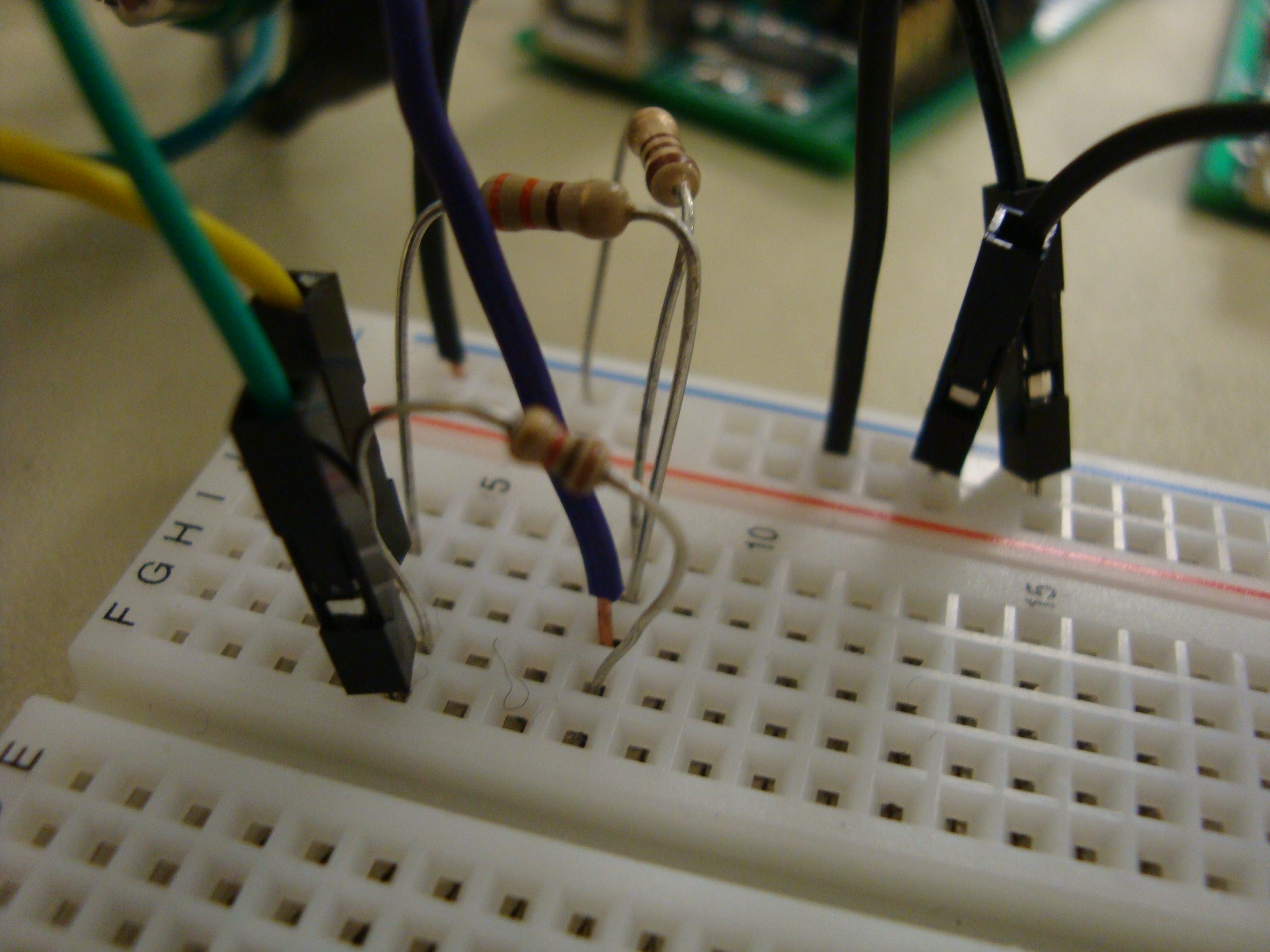
The microphone must be biased at 5V DC for its internal transistors to work properly. However, we do not know exactly what the microphone output looks like other than that sinusoids are centered around some DC value. We pass the mic output through a DC blocking capacitor to isolate the AC component. The ADC on the microcontroller reads values from 0V to 5V, so to get maximum resolution on our data, we want it to be centered at 2.5V. The preamp stage uses a 2.5V reference to DC bias the signal around 2.5V. We also choose our resistor values to add a high gain (~43) to the signal so that it uses up as much as possible of the ADC's 2.5V amplitude allowance.
Once the signal is centered and amplified, we use a first order active bandpass filter with a passband from 190 Hz to 970 Hz, which is the range of frequencies that we are interested in capturing. However, the unity gain bandpass filter lowers the levels of the signal, so we add another low pass filter with a cut off of 970 Hz but with a gain of 2 to bring output levels back up. Cutoff frequencies for these filters are determined using the usual method of fc = 1/(2*pi*RC). Fig. 6 below is shows the schematic for this part of the circuit. There is one RC low pass filter there that is not shown in the schematic that is in the photo of our board to the left. We used it to display the PWM signal onto the oscilloscope while debugging, but it is not a part of our final design.
Information Transfer Between Chips
The ADC of MCU1 reads the output of this stage, and the chip processes the signals to extract pitch and duration information for each note (see software section below), and transmits the information to MCU2. The connection between the two chips is simple: to use the UART to transmit characters, we simply linked the Transmit (tx) pin of MCU1 to the Receive (rx) pin of MCU2. A diagram of this connection, as well all other schematics, is available in Appendix B, and a photo of the connection between our two MCUs is included in the panel on the left.
Video Generation
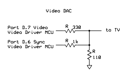
On the video end, a simple resistive network creates a Digital Analog Converter (DAC) to attain the appropriate voltage levels for the sync pulse and video pulse width modulation. The schematic is included in Appendix B, and the connection between the resistor network and the television is pictured on the left-hand panel. Note that all circuit components were connected to a common ground.
Software
All our code is included in Appendix A. Borrowed code is referenced in Appendix E.
Fixed Point Math
We included the fixed point multiply and the fixed to non fixed conversion definitions written by Professor Land. We needed the fixed point multiply for the FFT algorithm we used. The multiply was written in assembly, and is the only usage of assembly in our code.
UART Intialization
We used the uart.c, uart.h, and uart initialization code that we have been using in all of the labs since the beginning of the semester. However, we changed it to remove the special cases that are performed for numbers 7 and 10 so that we could transmit those as well. This change can be seen in uart.c in Appendix A.
Intialization
We initialized port A0 of the ADC, which we are using that to sample the output of the filter and amplification white board. Timer2 is initialized to interrupt at our FFT sample rate, 2000 Hz, chosen for the reasons described in the background math section above. Port D2 is set as an output since it is connected to the led on the target board and is used as a metronome. Several global variables that are used later are initialized to 0. A PWM channel is set up on PD5 since it can be used to display the envelope of the signal output from the amplification and filtering board on the scope. This was not required in our final demonstration, but we left it in because it was very useful for debugging. Finally, the interrupts are enabled.
ISR
The ISR is used for three main purposes: Timer 2 is used to sample the audio signal at 2 kHz; toggling PD2 causes an LED to blink at 100 beats per minute, acting as a metronome; and note length calculations. The ADC output has 0V at 128, positive numbers above that, and negative numbers bellow that. In the ISR, the ADC output is rectified by subtracting out the 128, and then taking the absolute value. This rectified sine wave is passed through a Cascaded Integrated Comb (CIC) filter and then a low pass filter.
The CIC algorithm was taken from the DSP link on the course website. We used the fourth order four times down sampler version to get the resolution required for our project. We needed to down sample before our low pass filter since digital filters' cutoff frequencies are a percentage of the sampling rate, and the sampling rate is easier to modify. We would have like to downsample by more than 4 to further eliminate the effects of noise, but when we tried to raise the down sample amount, the CIC code stopped working for reasons we still do not understand.
For the final low-pass filter, we adapted a one-pole Butterworth filter from in the Karplus-Strong section on the DSP link on the course website and cascaded it to low pass the output of our CIC code to get the envelope. The necessity of the low pass filter is described in the background math section above.
All borrowed and adapted code can be found in Appendix C.
After the envelope is extracted from the low pass filter, a series of conditional statements are used to detect rising and falling edges using the algorithm described earlier. The ISR also sets the pulse width modulation duty cycle to be proportional to the envelope, which was then low-passed to be displayed on the oscilloscope for debugging.
The ISR also measures the time between two rising edges in milliseconds, and also on every rising edge sets a flag called newNote. When there is a new note and the buffer isn't already full with samples from the current note, the ISR stores 128 samples into a buffer for use in the fast Fourier transform portion of the code.
Main
Main starts by running the initialize function, creating a table of sine values that is used by the fft algorithm and then entering the while loop. The loop repeatedly checks if the sample buffer is full. If so, it transfers the samples to a new array and clears the buffer and then clears a flag so the ISR will begin refilling the buffer. It then runs the FFT algorithm on the sampled data.
The fft algorithm we used was taken from the DSP link on the course website, where it is altered from its original version to only take real inputs and transform in the forward direction. Only the first half of the real first half of the real inputs (and therefore the first half of all the outputs) is meaningful for our use. We set it up to sample 128 points to get maximum resolution without causing memory overflows as previously described.
After the FFT finishes running, function findMaxes takes its output and stores the index of the fft output that has the maximum amplitude as described in the background math section above. We originally tried using the amplitude values to determine note lengths, but found they were too unstable (possibly because of the optimization used to calculate them) did not correspond well enough too overall volume level.
The main loop then stores the last detected note in into a variable called lastNote. This is because the most recent note length calculation from the ISR corresponds to the previous note, as the length of a note can only be determined after it has ended, i.e., after the next note has been played. Finally, functions noteSelect and lengthSelect take the frequency and time information associated with a note and use conditional statements to translate those numbers to char indices that can be decoded by the video code. Function noteSelect can use a simple Switch-Case statement because there is a discrete number of frequencies in which we are interested; lengthSelect, on the other hand, has to recognize a large range of times as corresponding to a certain type of musical note, so it uses traditional if and else if statements.
Lastly, if the note that was stored in lastNote isn't 0, which will happen if the FFT doesn't recognize the note or it is too short to be picked up by the envelope detector, then the note code and the length code are sent to the video MCU using the UART as described below.
Inter-chip Communication
Our inter chip communication is very simple. The TX (transmit) pin of the UART on the note processing MCU is connected to the RX (receive) pin of the video driver MCU's UART. Whenever the note processing MCU has a new note it sends two characters, one representing the note pitch and one the note length to the video driver MCU using the uart_putchar command. The video driver MCU checks its UART's receive flag, which tells it if there is unread data in its receive buffer, at the beginning of every time through its main loop. If something has been received it reads the UART's receive register, URD0. Note codes have a 0 as their most significant bit, and length codes have a 1 to ensure that the video driver MCU can tell them apart correctly. The subsequent sections explain how the video code uses the output of MCU1 to display musical notation on at TV.
Global Variable Declarations
Initially, some variables are declared for video output and some for plotting. The former came with the video code. The latter include the global position pointers, constant y values for drawing each pitch, a variable to denote which sort of accidental to use, and a flag to indicate a switch to a new, blank staff page.
Video Code
This code was provided by Prof. Land on the Video on the GCC page, and we have not altered it. It includes an assembly routine to interpret and place a byte of information to the screen, and a function byteblas() that uses the assembly routine to write many lines to the screen.
ISR
This portion also was written for us in the video code provided by Prof. Land. We tweaked it slightly in an attempt to get the LED to toggle, but it seems that the video code uses PORTD in such a way that makes this impossible. Our changes did not affect the functionality of the video code (for the original, see Appendix E), so we have not changed it back. The ISR generates the sync pulse and video is outputted for the first 231 lines of every frame using the function in the immediately preceding section.
Basic Plotting Functions
The code from the 4760 website includes many basic plotting functions for lines, points, determining the value of a point, printing characters, etc. We have used the point- and line-plotting functions exntensively, and have removed the rest from our code.
Note Plotting Functions
These were written after long hours with graph paper to determine each pixel location for each musical note or object. One of these sheets of graph paper is pictures on panel on the left. Given the video_pt and video_line functions, the rest were not difficult to write.
In addition to drawing the note, these functions increment the global x position to be two pixels greater than their width by calling incGlobX(). This function not only increments the x value, but determines if the x value is far enough along that a new line of the staff should be used. If the last line of the staff has been used, it sets a flag, newScreen, that the main function acts upon to clear the screen and start over. Functions that call other drawing functions are written so that glob_x is not over-incremented. This was tested by displaying each type of note on the screen and making sure note spacings were reasonable.
Main Function
The main function initializes variables for note pitch and length, and the newNote flag. It also initializes the ports used by the video sync and those used to determine whether to draw flats or sharps. We accomplished this by attaching a jumper to either PC1 and PC2 to indicate sharps or PC2 and PC3 to indicate flats. Since this declaration happens only once every time the board is prorammed, to change the setting, one must reprogram the board. The function then initializes the UART so that it can receive information from the other MCU, draws the staff and clef, enables interrupts and enables sleeping. Sleeping is important because the video sync must begin from the same state every time, as is specified by the video code.
Each time the code wakes up from sleep, it checks to see if there is new data in the receive buffer. If there is, it determines whether it's a pitch (0 as the most significant bit) or lenght (1 as the most significant bit). Since lengths are sent second, if it's a length, a flag is set to indicate that there is a new note for which there is more information. It's okay to check for new notes once per for loop because this code is executing a lot faster than a user can be playing.
The next segment of code checks the newNote flag, and if there is one, it decodes the information and draws it to the screen. In addition, if the newScreen flag has been set by incGlobX(), then it temporarily disables interrupts, clears the screen, draws a fresh staff set, resets the newScreen flag and re-enables interrupts. The disabling of interrupts is essential, because trying to sync while the screen is being cleared causes problems. Screen clearing is accomplished by setting each pixel to black.
Note Length Choosing Functions
The functions drawNoteUp and drawNoteDown simply use a Switch-case statement based on the length sent by MCU1 to draw the appropriate note at a given location. They are called only by the main noteDecode function, described below, which feeds them the coordinates so that they need to do no calculation and can just draw. These functions could probably be combined into one function a second draft of the code.
Note Decoding Function
This long function is really just a large switch case statement. It takes several things into account. It switches on pitch, adding a global value to the global y-coordinate to place the note in the correct vertical position on the staff. However, before calling the function to draw the note, it draws the accidental if appropriate, then the ledger lines, and then finally the note. This order is important because accidentals increment the x position variable, and are always drawn to the left of the note head, so they must be drawn first. Ledger lines need not increment the position variables, so they must be drawn before the note itself is.
Particularly Tricky Components
The most challenging part of the project by far was determining the envelope of the signal so that we could determine note lengths. We tried several algorithms including counting FFT samples at the same note and different types of digital filters, before settling on the final one. We tried looking for a derivative switch from negative to positive, a switch in the derivative value averaged over several cycles, using the FFT amplitudes, and a couple other things, though all of them either never triggered or had a bunch of false positives. Also, the PWM output showed that a few of the notes (particularly As and Ds) had some very odd noise characteristics and would oscillate wildly around the expected general shape. Some notes were also more prone to being aliased down an octave (to half their frequency), even though they were well below the Nyquist rate. This could be due to some undiscovered problem in our digital filtering or a problem with the instrument itself, but our algorithm was able to handle this noise and still have decent performance. However, if these problems did not exist, we would have been able to set tighter thresholds and therefore detect faster notes.
Testing
To test and debug our system we used a variety of different methods. At first we used the UART and LEDs on an STK. The UART allowed us to print a large variety of types, while the LEDs allowed us to test character and integer values even within an ISR. Our programs didn't require the use of PORT C, so we connected that to an LED bank and used them. Later when we moved to a target board we could no longer do this, but we made heavy use of the one LED on the target board to toggle inside various conditional statements to see when they were executing. This was particularly helpful when debugging the code that found rising and falling edges as we could toggle it whenever it detected an edge to see if it was working.
We also set the envelope level of our audio signal to the duty cycle of a PWM channel and put that through a low pass so we could see the signal on an oscilloscope. This helped tremendously with debugging the note length algorithm since we could see what sort of noise we were dealing with.
When debugging the video code, fprintf() used too much memory and crashed out code since the video buffer itself took up most of the chip's memory. So we instead used uart_putchar() directly to print to the terminal to debug the code.
Results
Speed
From the user's perspective, this system is essentially real-time: a note displays on the TV screen as soon as it is over. While spectators have remarked that it seems odd that a note shows up as soon as the next one is played, this is actually only natural. A note's length cannot be determined until the next note is played, because that is the only indication that the previous note has ended. Since one note in music conveys informatino about both pitch and duration, a note can be displayed at most as soon as the next is played.
We would have like to be able to detect faster notes than we were able to, but we were seriously limited in this respect by the envelope of the waveforms synthesized by the piano. More pronounced peaks in volume and faster decay times once a key was lifted would have enabled us to greatly increase the speed at which people could play and still register notes correctly. It is possible that using a different keyboard would have mitigated this problem, but that was not an option given our budget.
Accuracy
The accuracy of the video, which is the output from our system, is measured with respect to pitch, rhythm, and musical notation.
Pitch
Pitch determination was nearly 100% accurate within our chosen range (A3 to A5, or 245 Hz to 970 Hz), because of the parameters we chose for the FFT. In several days of testing, we did not have any problems with notes with frequencies somewhat close by being mistaken for each other by our algorithm. There are two problematic notes, however, that are aliased down one octave about 5% of the time that they were played, irrespective of duration. Because the aliasing was always exactly an octave apart, we believe that this may be due to the output waveform of keyboard, which could have a stronger first harmonic frequency component for those specific notes.
We did not fully account for key signatures, but did allow a user to move a jumper to select whether flats or sharps would be displayed. This is a reasonable design choice because most of the simple melodies that will register fully with our system generally do not have key changes that require displaying both flats and sharps at the same time. This jumper is shown in a photo on the left-hand panel.
Here is a video that demonstrates music displayed with sharps and one with flats. Both use "Frere Jacques" to demonstrated, the former in the key of D, and the latter in the key of Eb. These videos were taken before we were finished fine-tuning the code, so there are some bugs in parts of them, but they display the flats and sharps correctly. Finally, this video shows a perfect capture of "Ode to Joy", which was stuck in everyone's head by the time we demonstrated our project.
Rhythm
We would have liked to be able to do more rhythmically, but we were severely limited in speed by the noisy envelopes of the musical signal. However, the system picks up eighth notes through whole notes quite well at the 100 beats per minute tempo that we have hardcoded. Humans are actually fairly bad at timing notes (the ear is a forgiving input device in this respect), so until a user gets used to playing at the specified tempo, it is not unusual for some quarter notes to register as dotted eighth notes. Decreasing tempo would increase accuracy because the bins into which each note could fall would become larger, but most simple songs that we wanted to use to test the system will sound rather boring at lower speeds, and since we found that a little bit of practice drastically decreases rhythmic accuracy (by the second day, we were playing 30-second clips without any rhythmic mistakes), we decided to keep the higher tempo.
Though it would have been easy to do so, we do not draw measure lines, because that would be assuming a certain time signature, which we have no way of setting. This way, users can play in whatever time signature they choose as long as they can keep the beat (duple, triple, or otherwise).
Musical Notation
The aspects of musical notation that have been included in this design work essentially perfectly when given the correct note codes by the input processing MCU. Once the artwork was completed, there was little alteration required to the video code. However, due to time constraints, we did not include several important aspects of musical notation, such as rests, bar lines, and altered symbols for eight- or sixteenth-note pairs.
Safety
Our design is very safe. Other than pressing the keys on the piano there are no moving parts and there are no high voltages anywhere in our circuitry. The only somewhat risky part was soldering our two target boards. We took ample precautions by wearing safety glasses when soldering, only holding the soldering iron in our dominant hand and never pointing it towards ourselves or other person, keeping the iron in its holder except when actively soldering something, and being generally cautious and aware of our surroundings.
We did run into one slight safety hiccup when building our circuit, though. Initially, the output from the serial to USB converter seemed to be incoherent. We later realized that this was likely due to the chip running on its internal clock rather than the 16 MHz external clock. However, at that time we decided to check for shorts in the soldering of the USB IC. We disconnected the power connector from the target board before using the multimeter but forgot that USB itself was powered and accidentally shorted USB to ground with the multimeter probes. The chip started smoking so we immediately took the probes away, and removed the USB connector as soon as we realized what had happened. We then removed the IC itself and checked for shorts before powering up the target board again.
Interference with Other Projects
People working on or using their projects often created a lot of noise, so the background noise level in the lab was often fairly high. This somewhat interfered with our project, and we had to raise the volume of our piano higher to compensate. Of course, this probably caused some interference to other groups as well. We also taped the microphone to the speaker of the piano, which helped it register the piano output much more accurately against the background noise.
Usability
Several people were able to use the system with minimal instruction. We included an LED blink that functions as a metronome to help the user play in tempo, thereby helping the software identify the correct note length. Thus, anyone who can play a piano reasonably in tempo can get good results from the notator. A couple of tries to better acquaint the user with the instrument (for example, sustained notes sometimes don't register as well as staccato ones) help greatly, as hitting the keys in a manner that coincides with the LED blink and outputs as smooth a waveform as possible takes a little getting used to. As designers, we have little control over this aspect, because the instrument that we are working with has its intrinsic inconsistencies.
A common consideration in music is usability for those who are hard of hearing. Since the microphone requires a fairly high volume to function anyway, those who are slightly hard of hearing should not have too difficult a time.
Practicality
Currently, both tempo and pitch are hard-coded in the design: the pitches used are those output by the Casio keyboard (it's an old keyboard, and is a major second below concert pitch, though we discovered too late that its intonation can be slightly adjusted) and the tempo is fixed at 100 beats per minute. As described in the discussion on accuracy above, it is also missing a lot of the elements of musical notation.
Thus, in its present state, the notator is a lot of fun to play with, but not actually a useful tool, because it only captures music correctly that can be fairly easily scored by hand. However, with a little more memory, processing power, and time, it would not be difficult to create a more widely usable system in which tempo and pitch could be calibrated for a specific user or instrument and displayed a more full set of musical characters.
Conclusions
Recommendations for Further Development
In terms of detecting pitch and displaying notation, this project met our expectations. As previously mentioned, we would have liked to have a little more flexibility with tempo, and had we not spent as much time trying to tune our system to messy envelopes, we would have been able to do more with other parts of the project. However, we feel that for the amount of time we were given to complete it, we have produce a sufficiently complex and interesting system.
There are many things that can be added to this system without a great deal of effort. These include: tempo calibration rather than hardcoding; pitch calibration rather than hardcoding; more robust musical notation; and connecting to a computer and saving the score.
Adherence to Standards
Our design conformed to applicable standards. We conformed to the normal usage of a UART for our inter chip communication and we generally confirmed to the NTSC standard when displaying video onto the television. Both have been discussed in more detail in previous sections.
Intellectual Property Considerations
We reused code for the video display from Lab 3 and code for the FFT, CIC, and low pass filter from the DSP page of the course website. We have permission to use all of this code in our project. We did not reverse engineer anything, sign any non-disclosure agreements, or come across any patents or trademark issues so there are no IP considerations there. There aren't really any patents or publishing opportunities since similar commercial products do exist. Using an FFT to determine pitch is a standard practice, and while our note length algorithm is nice it is probably too specific to be worth patenting or publishing. The only IP considerations are that if you play a copyrighted work on the piano you are then displaying essentially the sheet music to a copyrighted work on the television which is similar to reproducing a copyrighted work. But we have been testing with songs that don't have an active copyright such as Ode to Joy and Twinkle Twinkle Little Star. This would likely fall under fair use as well and there is no way to store the notes produced.
Legal and Ethical Considerations
Our project is consistent with the IEEE code of ethics. It in no way endangers the safety, health, or welfare of the public. In fact, the choice to make a device that would make composing music easier is by itself very consistent with the IEEE code of ethics since it could only promote public welfare, since music and entertainment in general enrich people's lives and bring them together in enjoyable social interactions. Furthering art is generally considered an ethical undertaking.
We are also honest in stating the claims of our device to anyone that asks in a way that is consistent with the IEEE code of ethics. We say that it can reproduce melodies with no chords to a reasonable accuracy and with a reasonable speed and note range, but we make no claims that it will be 100% accurate every time or recognize very fast notes over any range since that would be untrue and unethical. Furthermore, conducting this project helped to improve our technical competence and understanding of technology, which is an ethical pursuit according to the IEEE code of ethics. By doing this project we learned how digital signal processing can be used to analyze music, something with which we personally hadn't had much experience with prior to this project.
Throughout the project we sought honest criticism about our project from those working around us and took any such criticism to heart. Furthermore when testing our project we tried to not overly annoy others with our music playing by only testing for short periods at a time which is consistent with the IEEE code of ethics mandate not to injure others.
Acknowledgements
We would like to thank Professor Land and the TAs for their help throughout the project, and especially with note length detection.
Appendices
Appendix A: Budget and Parts List
| Part | Source | Unit Price | Quantity | Total Cost |
|---|---|---|---|---|
| Total | -- | -- | -- | $68.69 |
| Mega644 chip | 4760 Lab | $8.00 | 2 | $16.00 |
| Black and white T.V. | 4760 Lab | $5.00 | 1 | $5.00 |
| Custom PC Board | 4760 Lab | $4.00 | 2 | $8.00 |
| Breadboard | 4760 Lab | $6.00 | 2 | $12.00 |
| 2.5V Reference | Digikey | $3.47 | 2 | $6.94 |
| FT232RL TSSOP Serial-USB Connector | 4760 Lab | $4.00 | 2 | $8.00 |
| DIP socket | Digikey | $0.50 | 2 | $1.00 |
| Casio Keyboard | Previously Owned | $0.00 | 1 | $0.00 |
| Microphone | 4760 Lab | $0.00 | 1 | $0.00 |
| 1-pin jumper cables | 4760 Lab | $1.00 | 8 | $8.00 |
| ISP head pins | 4760 Lab | $0.05 | 75 | $3.75 |
| Wire, Misc. Other Components | 4760 Lab | $0 | -- | $0 |
Appendix B: Schematics
Musical Signal Processing - first white board
Connection between the 2 MCUs
Video DAC - second white board
Block Diagram
Appendix C: Code Listing
Video Code
Musical Signal Processing
FFT
Function noteSelect
Function lengthSelect
UART C file and UART hex file
Appendix D: Distribution of Tasks
-
Stephen Prizant
- Soldering prototype boards
- Inter-chip communication
-
Ragini Sharma
- Video art and logic
- Web Page
-
Joint
- Implementation of pitch and length detection
- Testing and debugging
- Final Report
Appendix E: References
Code
FFT,
CIC filter,
and Karplus Strong filter
used unadapted from the ECE 4760 DSP webpage
Video generation code adapted from ECE 4760 Video Page
Parts
Prototype Board from expressPCB
2.5V Reference: Part Number REF192GPZ-ND from Digikey
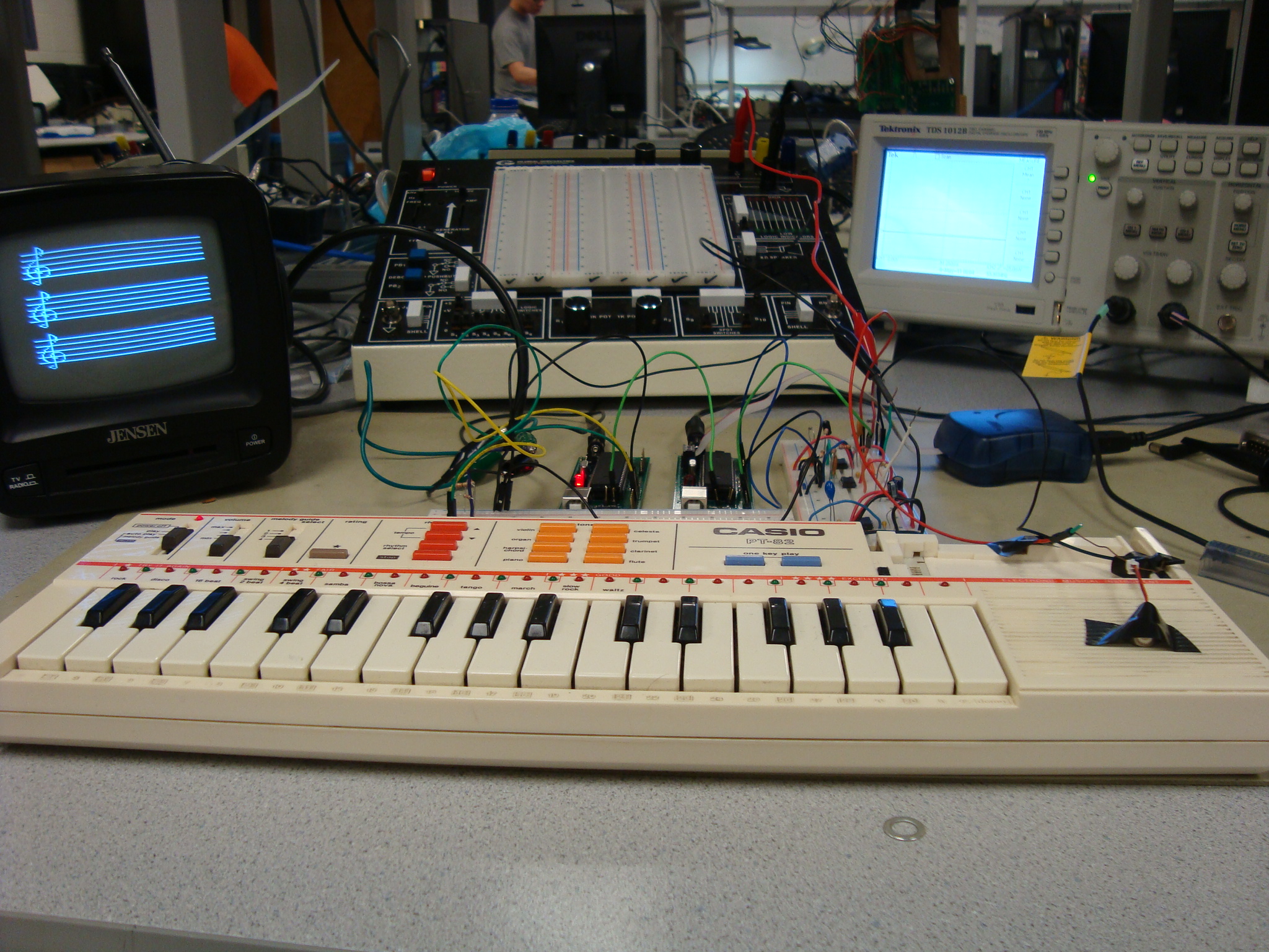
The full setup.
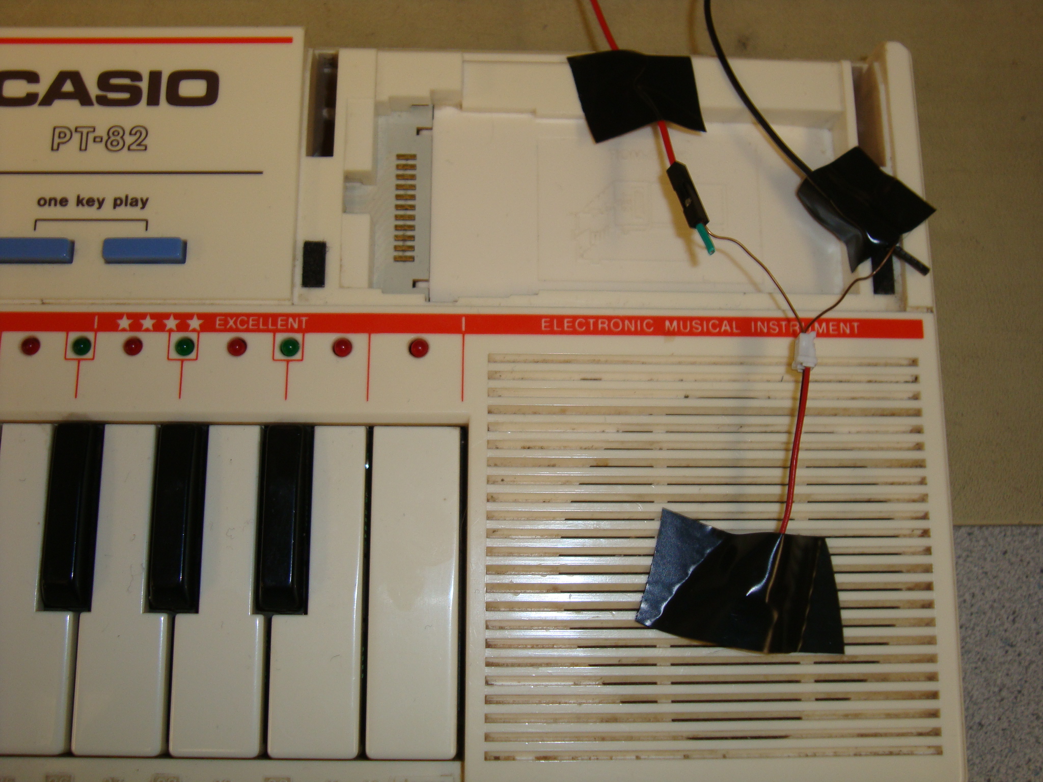
We taped the microphone to the piano speaker so we wouldn't have to play as loudly for everything to register.
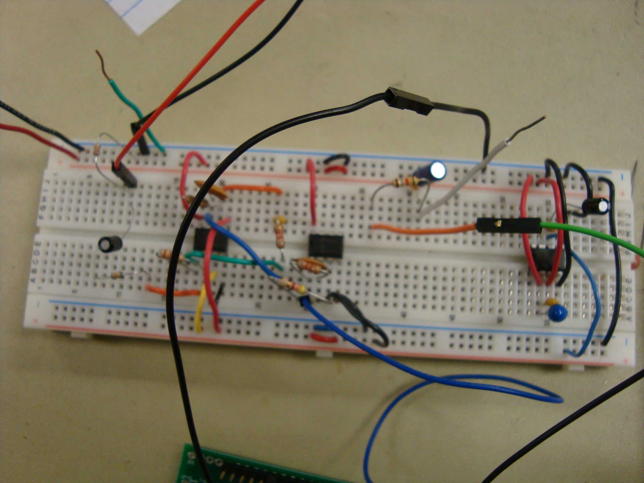
White board with the hardware for all the input signal processing.
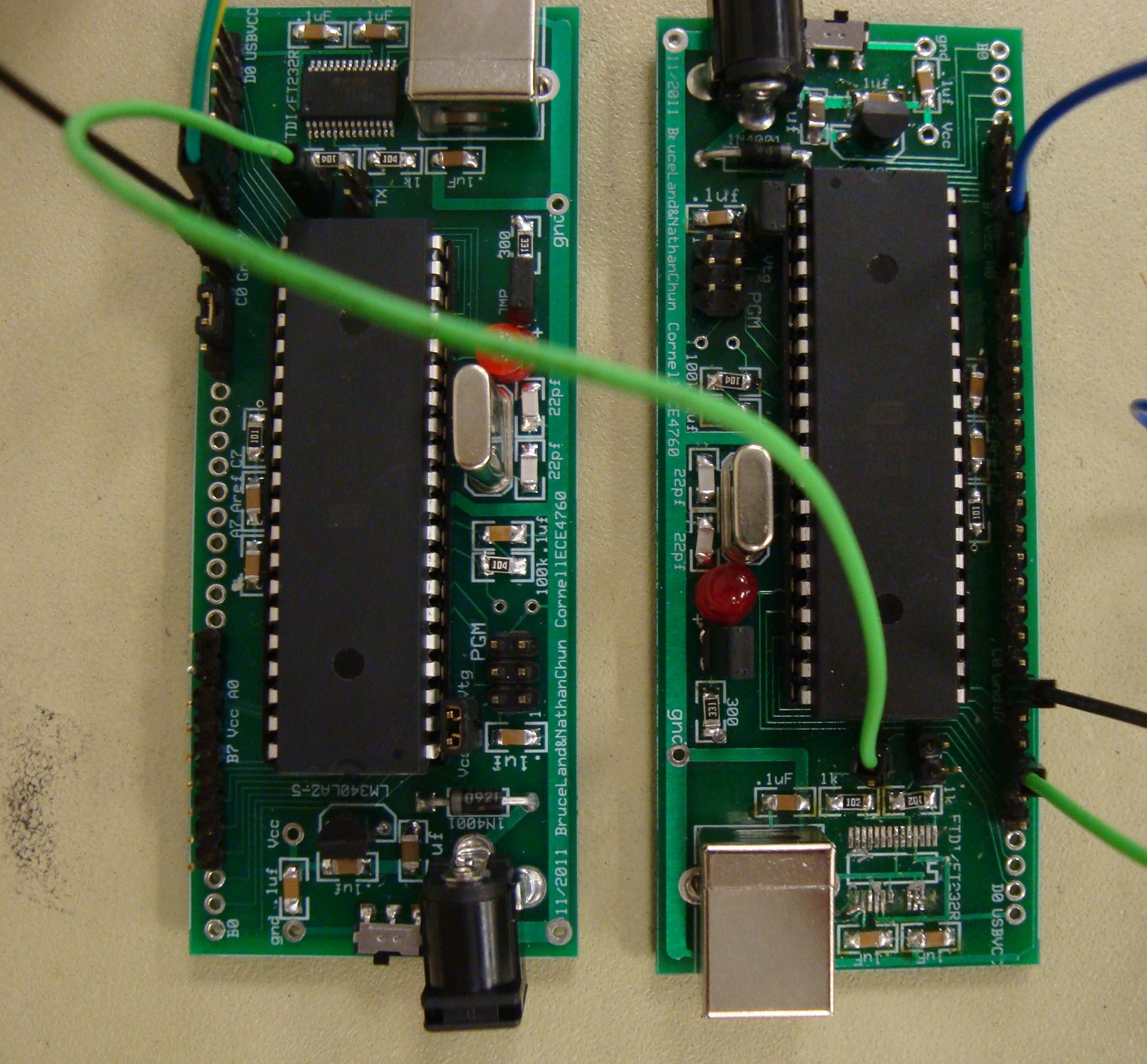
The bright green wire connects the transmit pin of the audio processing mcu (right) to the receive pin of the video processing mcu (left).
We moved this jumper between two pairs of pins to set whether to display flat signs or sharp signs.
DAC used to connect the video signals to the television
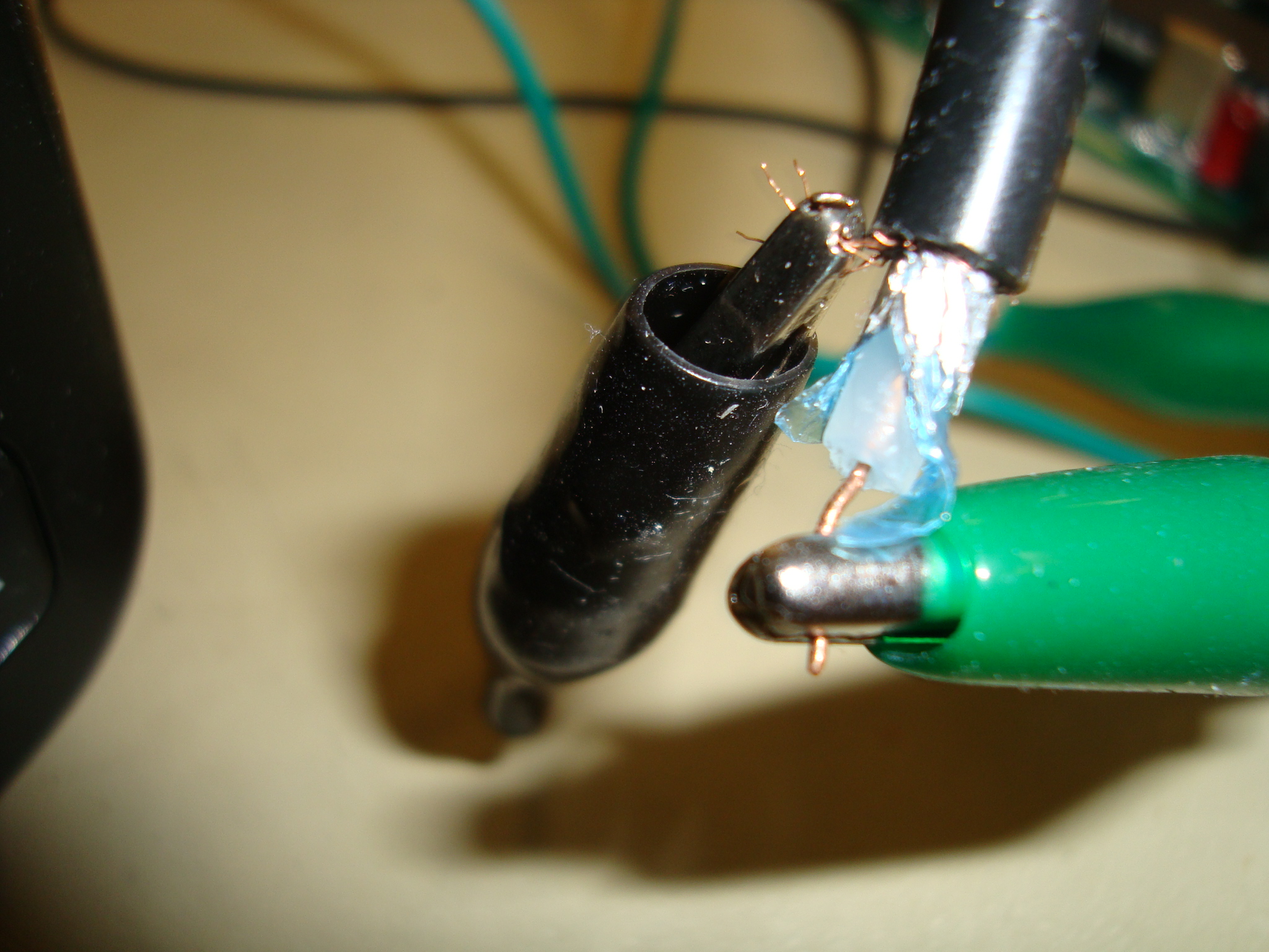
Output from the second mcu was fed through the DAC into a coax cable for the Video input to the telvision.
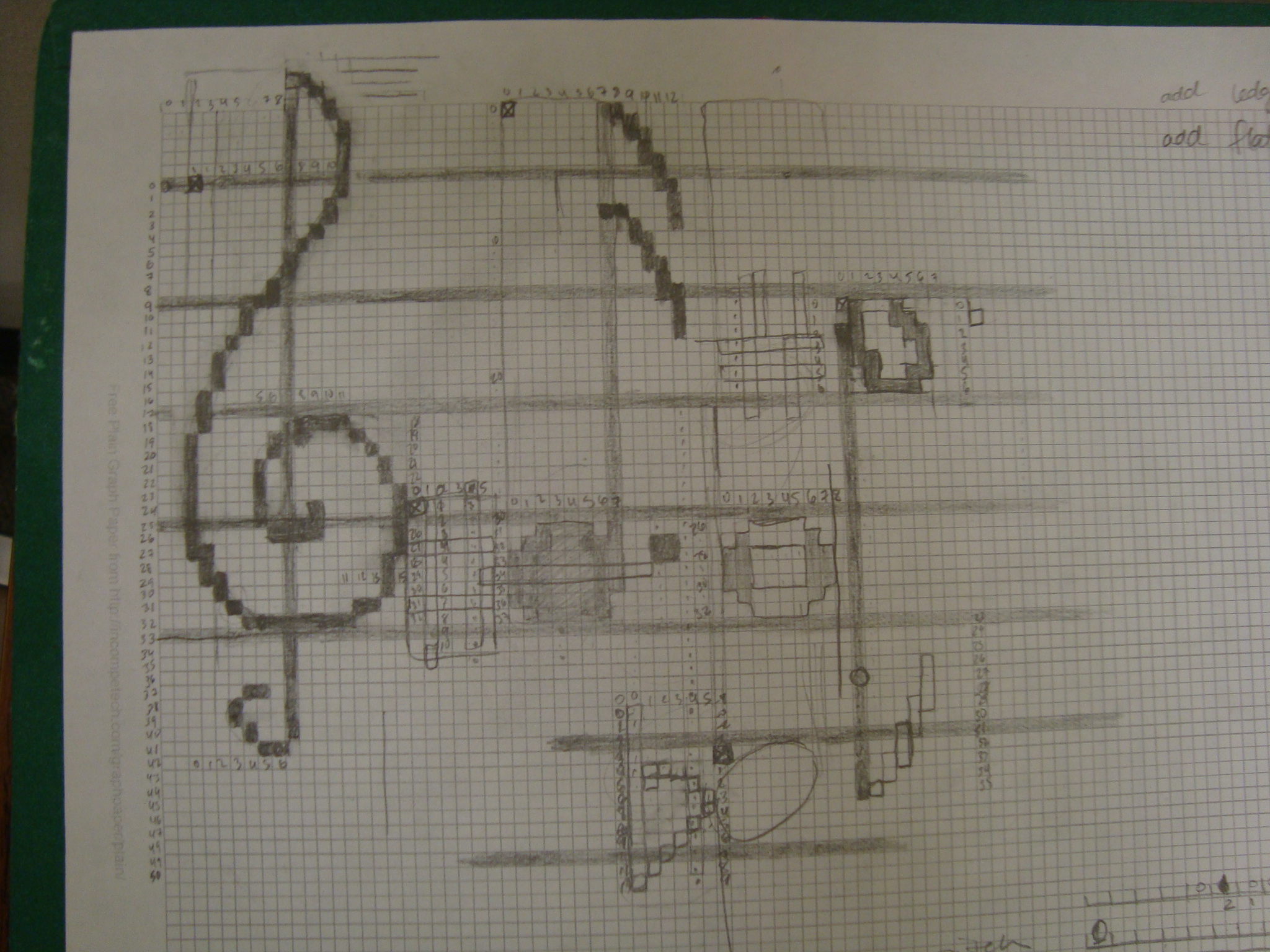
We went through lots and lots of graph paper before we got to the tv screen.
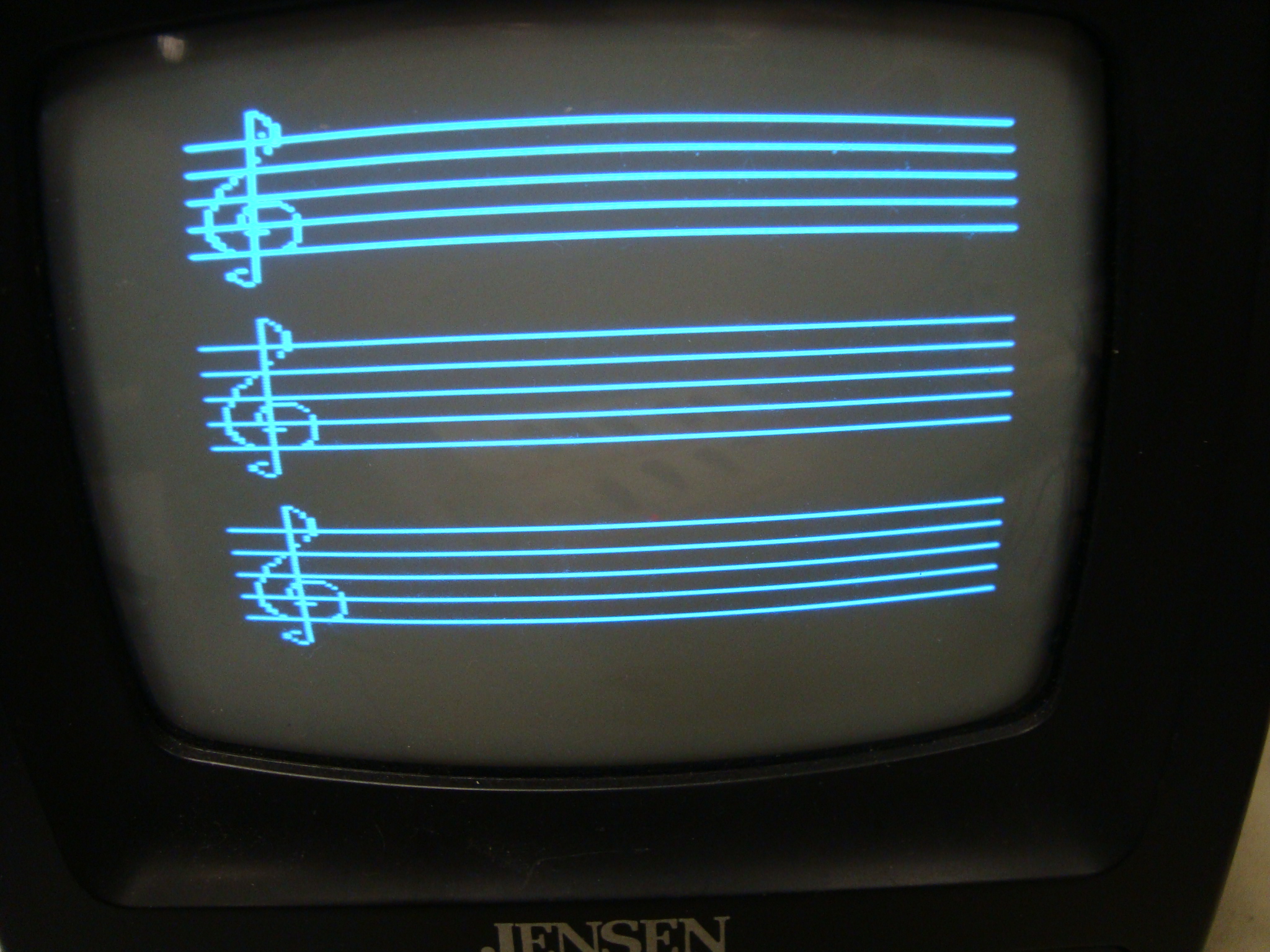
Blank staff displayed on startup
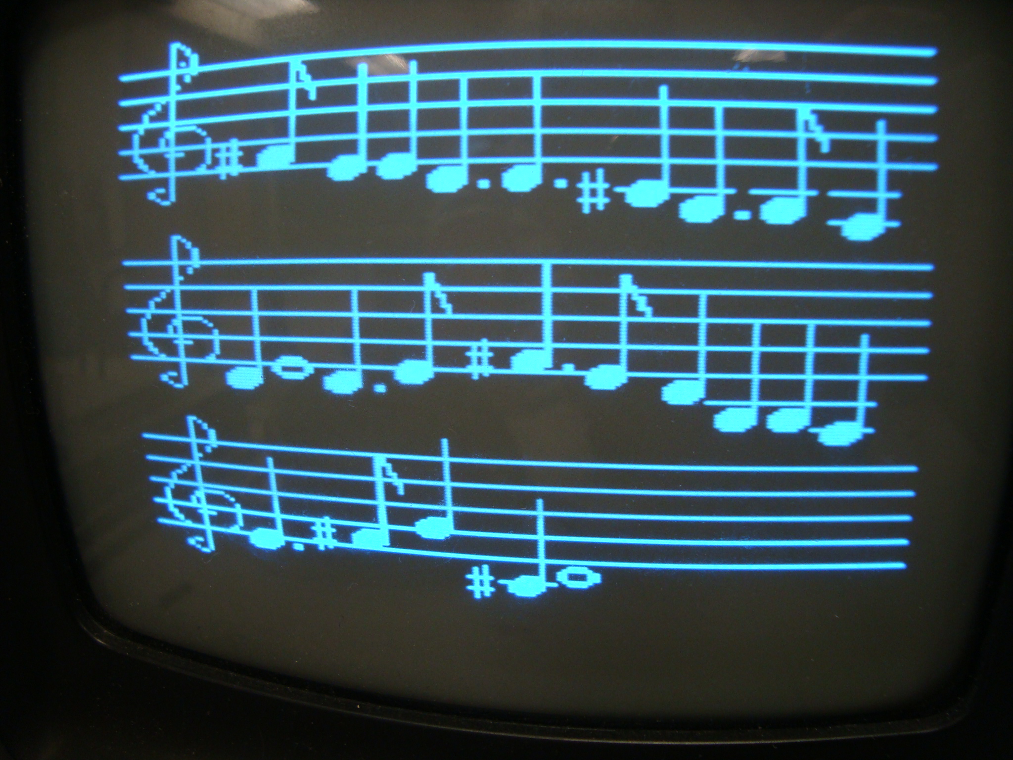
The output for the Cornell Alma Mater, "Far Above Cayuga's Waters" in D major. This is the second page.