The signal value U is sent continuously to the driving circuit with every corresponding new output begin measured as the process continues. Table () summarizes the pros and cons of each term of the PID controller.
The most common controller used in the HVAC industry is the proportional, integral, Derivative PID controller. In brief, Proportional, Integral, Derivative PID controller is a feedback controller that helps to attain a set point irrespective of disturbances or any variation in characteristics of the plant of any form. It calculates its output based on the measured error and the three controller gains; proportional gain Kp, integral gain Ki, and derivative gain Kd. The proportional gain simply multiplies the error by a factor Kp. This reacts based on how big the error is. The integral term is a multiplication of the integral gain and the sum of the recent errors. The integral term helps in getting rid of the steady state error and causes the system to catch up with the desired set point. The derivative controller determines the reaction to the rate of which the error has been changing. In most of the HVAC systems, it is not necessary to use the derivative part of the PID, hence in this project, only PI controller has been designed and used. The final output of the controller (U) is calculated using the following equation:
![]()
The signal value U is sent continuously to the driving circuit with every corresponding new output begin measured as the process continues. Table () summarizes the pros and cons of each term of the PID controller.
Controller |
Pros |
Cons |
P |
|
|
PD |
|
|
PI |
|
|
Table (1) : summary of the affect of changing PID functions
The wind up action happens when the output of the controller reaches saturation (255 for 8bit PWM). Due to the error is still positive, the integral part continues to increase causing more inputs applied to the system. This causes the control signal to remain in saturation and the feedback loop is basically broken. This windup action is avoided by restricting the output signal of the controller (U) to be within the acceptable range of the actuator. Here, we have restricted the output signal between 0 to 255 (8bit PWM signal).
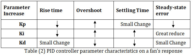
There are a couple of strategies on how PID can be tuned; this includes trial and error tuning method, Ziegler-Nichols tuning method etc. Our approach was calculating the controller output function U such that the final output signal (U) applied to the actuating circuit was divided by the number of shifts determined in PID structure. This is a systematic way of changing the PID parameters. We started by 7 shifts to the right; meaning we divided the output signal by 2^7 or the value 128. This way we are half way through either increasing division factor by 128 or reducing it by 128. We started by making an initial guess of the value of the Kp gain where Ki=Kd=0. We noticed that when Kp had a large value, we had a faster rise time, but an increase in overshoot. To improve on the effect of Kp, an additional Ki was also set to a small value. Adding integral gain had a great effect on reducing steady state error between the desired temperature and the actual temperature. The following table gave us a rough idea of how changing each PID parameter could change our system response.
After establishing a functioning single input, single output PI control which was the simplest in design since we used data from one sensor to control one actuator, we moved to designing a single input, multiple output SIMO PI control as shown in figure (2). In this case we used one data from one temperature sensor to control both the Peltier Heater and the fans on the heat exchanger in the condenser loop. In this case, both controllers were aiming to meet one set point, the advantage of such a method is that we could reach to the set-point faster than before but amount of overshoot set point increased. To overcome such a problem, we detuned PI gain parameters and after tuning both controllers, we were able to get a very good response.
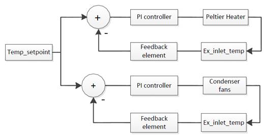
Figure (2) Two SIMO PID loops
Table 3 summarizes the best gains at which we got the best response with less oscillation and faster rise time.
|
PID type |
Kp |
Ki |
Max |
Min |
Peltier controller |
PI |
20 |
1 |
255 |
10 |
Fan Controller |
PI |
20 |
1 |
255 |
0 |
After establishing a working SIMO control, we decided to implement two decoupled PI loops i.e. MIMO control. We worked on controlling the temperature of the chiller water supply loop. The first PI loop was to control the temperature of the Chilled water supply T_CHWS by controlling the Peltier Module. The second PI control loop was to control the temperature of the air supply AS by controlling the chilled side pump. The slower the flow rate, the longer the water stays in the cooling coil, the hotter the CHWR return temperature gets, This CHWSR acts as a load on the Peltier cold side, resulting in conveying more heat to the hot side of the Peltier. Figure ( 3) shows MIMO PI loops where one loop acts as disturbance. Such a system is difficult to tune specially, when one controller acts as a disturbance to the other controller.

Figure (3) Two MIMO PID loops