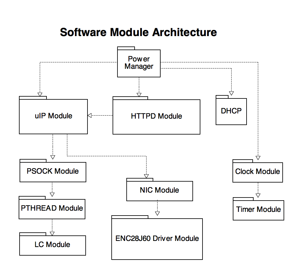
ECE 4760 Final Project Report


Adam Goudarzi (AG537)


Jeremy Fein (JDF226)

Introduction

Overview


PowerManager is a remote power management system that can be controlled through a web browser on a local area network (LAN). Devices plugged into PowerManager's outlets can be turned on or off with the click of a button on a webpage. PowerManager runs on an ATMEGA644 microcontroller and an ENC28J60 Ethernet controller. Together, this embedded system acts as a web server to serve a web page that allows the user to turn on or off the supply of power to the connected devices. The project serves as a fundamental element in a home automation system.

Rationale


These days, everyone has a smart phone in their pocket connected to their home LAN. With such a powerful device, why should anyone have to physically control their home's power and lighting? With the advancement of micro controller technology, it is now possible to have every device in a home be connected to a home LAN. These home devices can act as web servers to provide a web-based GUI to control and monitor the device. The simplest and most necessary kind of control is turning a device on or off. PowerManager fulfills this need in a standard way; any device with a standard electrical plug can be controlled (on or off) through home LAN.


High Level Design

System Overview


The PowerManager system is based on a client server model of communication. The PowerManager acts as a web server embedded on the ATMEGA644 MCU and ENC28J60 Ethernet controller. The MCU connects to the Ethernet controller through an SPI interface; the controller handles the physical and MAC layers of networking, and provides a standard interface to the MCU to send and receive packets. With this interface, the MCU is able to run IP, TCP, and HTTP layers. Additionally, the MCU connects through an audio cable to a power box. The power box contains a relay to control the flow of power to standard electrical sockets; the other end of the audio cable is used to control this relay, allowing full control of power from the MCU.

To use the system, a client (perhaps a browser on an iPhone) sends a request over HTTP to the PowerManager web server, which returns a page indicating the current state of power (on or off) and a button to toggle the state. When receiving a state change request, the MCU calls a CGI function to change its output to the power box, effectively changing the state of power flow to the electrical outlets. The flow of data through the system is best described in Figure 1 below.


Figure 1 : Data Flow

Software Overview


The design architecture for PowerManager can best be described on a modular level. The system is made up of both networking and system modules. The networking modules work together to provide data transmission and retrieval functionality. The system modules implement system dependent data structures and timers. All of these modules work together to provide the functionality that PowerManager requires to accomplish its goals. The module dependencies can best be described with a dependency flow chart in Figure 2 below.


Figure 2 : Software Module Dependencies

Hardware Overview


PowerManager uses an ATMEGA644 micro controller (MCU) embedded on the standard ECE 4760 custom PC board. The MCU connects to an ENC28J60 Ethernet controller chip through an SPI interface on Port B. A module for the Ethernet controller was custom built on a solder board, and appropriately connects the controller to power, ground, I/O, etc. The Ethernet controller runs a 3.3V, so a power regulator is used to drop the MCU's 5V VCC signal to 3.3V for the chip. Since the Ethernet controller's outputs to the MCU are at 3.3V, level shifters are used to turn the signal back to 5V. This is not needed in the reverse direction, since the controller's inputs are 5V tolerant. An RJ45 Ethernet jack is connected to the Ethernet controller.

In terms of power control, a custom power box was built. This box can plug into any standard U.S. electrical outlet, and contains 2 outlets, a master switch, and a 3.5mm audio port. Another audio port is on the MCU and wired to pin A7, and a 3.5mm audio cable can connect between the two. This audio cable provides input to a relay inside the power box, which controls the power from the main wall line to the 2 outlets.


Networking Open Systems Interconnection (OSI) Model


The OSI model is a standard way to do networking at all levels, from the physical electrons on the wire to the applications communicating with eachother. PowerManager implements all layers of this model. Figure 3 presents each layer of the model. In our system, the ethernet controller is responsible for the physical layer


Figure 3 : The OSI Networking Stack (src: WikiPedia)

Physical Layer

The physical layer is the first and lowest layer in the OSI model of computer networking. This layer abstracts different hardware transmission technologies on a network. The physical layer defines electrical and mechanical specifications for devices and is perhaps the largest and most complicated layer in the OSI model. Protocols in this layer define means of translating digital information into analogue signals and vice versa. It handles the bit by bit transmission of data over both wired and wireless communication mediums. PowerManager uses the ENC28J60 module to handle this layer, and allows the MCU to use this layer through an SPI interface.


Data Link Layer

The data link layer arranges the bits handled by the physical layer into logical sequences called frames. It abstracts the physical layer by providing the functional and procedural means to transfer data between adjacent nodes or devices in a network. The data link layer also provides specifications for correcting certain errors that may occur over the physical layer. The ethernet protocol is defined in the data link layer for LAN. Ethernet is a fundamental standard for networking primarily because it is the first layer where nodes are differentiated on a network. In the ethernet protocol each device is mapped to a globally unique 48-bit address. This address provides a means to route frames to their correct destination. PowerManager also uses the ENC28J60 module to handle this layer. PowerManager spltis this layer between the MCU and the Ethernet controller. The MCU must first generate (and write into it's device's EEPROM) a globally unique MAC address. Once this MAC address is configured and set, the ENC28J60 driver stamps packet headers with both this address and the MAC address of the device where the packet is designated to go. With this information, the Ethernet controller is then able to push data onto the network using a built in Media Access Control (MAC) module.


Network Layer

The network layer provides the functional and procedural means for communication among different networks. This is different from the data link layer because the data link layer supports communication in the same network. IP is the de facto communications protocol used for relaying datagrams across an internetwork. Although this layer is not entirely necessary for PowerManager, it provides the foundation for reliable protocols in higher layers like TCP. It also makes it possible to control power in devices that may be in subnetworks managed by multiple routers in an encompassing LAN. PowerManager handles this layer using the uIP module. This module handles stripping IP addresses from packets generated by a browser client. It handles both IPv4 and IPv6 addresses. The uIP module abstracts away lower layers by providing functions which accept any form of an IP address along with the content for a desired packet and interfaces with the NIC and ENC28J60 modules to correctly structure and transmit it. It also provides a means to accept packets in their raw form and deconstruct them to pull out the relevant information. PowerManager also uses the uIP module to perform Address Resolution Protocol (ARP) broadcasts and requests. ARP is a popular standard used to resolve an IP address from a MAC address. Every device on the LAN (including PowerManager) maintains an ARP cache which is necessary for routing packets to their correct destinations. ARP is necessary because IP addresses are dynamic and have the potential to change (unlike MAC addresses which are persistent throughout a device's life) with the devices life cycle within its network.


Transport Layer

The transport layer is the last layer that is relevant to the uIP module. It encompasses the most important protocol for PowerManager known as the transport protocol layer. TCP provides a reliable one to one connection between two nodes in a network. PowerManager requires this technology because it must only transmit and receive datagram packets with the client browser it is communicating with. TCP defines a standard to ensure that packets arrive in the correct order and completely. Even if this means that it must send multiple sub packets to get the information across. TCP is a complicated protocol and is beyond the scope of this design documentation. It's important to note however, that uIP handles all aspects of TCP like SYN-ACK connection establishment, checksums, datagram fragmenting, datagram assembly, and much more. uIP along with most of the other modules used in PowerManger was designed and implemented by other programmers that will be credited in the reference section of this report. We leveraged this module to help with the networking aspects of PowerManager. We also tweaked the module to make it work with our specific environment.


Hardware Design


Figure 4: Entire System


Figure 5: System Breakdown (without power box)

Micro Controller


An ATMEGA644 micro controller was used on the standard ECE 4760 custom PC board. A schematic of the board can be seen in Figure 6. This MCU is clocked at 16MHz. Since power is drawn from the MCU to power the rest of the PowerManager system (including Ethernet controller, RJ45 jack, relay, etc.), the standard 5V regulator provided with the custom PC board could not provide enough current. Thus, a larger 5V regulator was used with a heat sink to guarantee a steady 5V power supply with large currents. To provide a serial connection to UART for debugging, a serial port, custom ECE 4760 serial board, and a Max233CPP serial controller were used; pins D0 and D1 are wired to control this serial connection. The serial board can be seen in Figure 7. Additionally, pin A7 is used as an output to control the relay in the power box; outputting HIGH keeps the power on, while outputting LOW keeps the power off. This connection between the MCU and the power box is completely electrically isolated through the relay. A 3.5mm audio port is connected to pin A7 and ground; the stereo lines to the port are shorted together to produce a 2-pin port. A 3.5mm audio cable plugs into this port and then into the power box to transfer the signal.


Figure 6 : ECE 4760 Custom PC Board


Figure 7 : ECE 4760 Custom Serial Board

Port B of the MCU is used to interface with the Ethernet chip, primarily through SPI. Pin B1 is an input from the Ethernet controller and used as an interrupt for new packets or dropped packets. Pin B2 is an output that connects to a hardware reset on the Ethernet controller. Pin B4 is an output for slave select on the SPI interface. Next, pin B5 acts as a master out, slave in (MOSI) for the SPI interface, where the MCU is the master and the Ethernet controller is the slave. Pin B6 acts as an SPI master in, slave out (MISO) from the Ethernet controller. Finally, pin B7 is an output for the SPI clock. SPI is run at a frequency of the MCU's frequency divided by 16, meaning a bit rate of 1 MHz. Higher bitrates could be achieved if the SPI interface was done on an integrated PC board; however, our long wires connecting the MCU to the Ethernet controller requires a lower bit rate.

Ethernet Controller


The Ethernet controller used is a MICROCHIP ENC28J60 Stand-Alone Ethernet Controller with SPI interface. This chip contains a PHY module to handle the physical layer of the OSI model, a MAC module to handle part of the data-link layer, an internal buffer to store packets, and an SPI module to talk to a MCU. It runs at 25 MHz through an external 25 MHz crystal. The chip requires a 3V3 power source. Power is drawn at 5V from the MCU's VCC pin and passes through a LD117-3.3 regulator to produce a 3.3V signal; capacitors are used on the input and output of the regulator to remove noise in the power signal. The schematic can be seen in Figure 8 below, and a picture of this unit can be seen in Figure 5 above.


Figure 8 : 3.3V Regulator Circuit

The ENC28J60 chip is connected to a custom module built on a solder board. The schematics for this module can be seen in Figure 9 below, and a picture can be seen in Figure 5 above. Schematics were made in accordance to the data sheet of the chip. All constant 3.3V inputs to the chip have a 100 nF capacitor close by to ground in order to remove noise from the power flow. The RESET, CS, SCK, and MOSI pins are inputs to the controller from the MCU, and are 5V tolerant. The interrupt (INT) and MISO outputs, however, are at 3.3V; thus, level shifters consisting of two 2N3904 NPN transistors are used to create a non-inverted 5V signal from the original 3.3V signal. The TPIN-, TPIN+, TPOUT-, TPOUT+, LEDA, and LEDB pins connect directly to the RJ45 jack circuit (see next section). A 10 microfarad capacitor is used on VCap to bias an internal regulator to produce a 2.5V signal to power some of the internal modules of the chip.


Figure 9 : Ethernet Controller Module Cicuit


Ethernet Jack


The RJ45 Ethernet jack used is a MagicJack 10/100 BTX connector with internal magnetics and two LEDs. The schematics for the jack can be seen below in Figure 10, and a picture can be seen in Figure 5 above. Header pins were soldered to the tiny pins of the connector to allow standard conenctions to the rest of the board. A ferrite bead rated for at least 100 mA is used to reflect noise when transmitting packets; such a bead is not needed for receiving packets. Capacitors to ground stabilize the packet signals.


Figure 10 : Ethernet Jack Circuit

Power Box


The power box provides a standard way to control the flow of power to any device that plugs into a standard U.S. wall socket. A picture of the box can be seen in Figure 11 below, and its schematics in Figure 12. On the surface, there is a light switch and two standard plugs. The light switch is a master control override switch that can control the power flow into the relay; thus, this master switch overrides any power control made by the MCU. The box has a long cord to plug into any wall socket, providing the main power. This main power feeds into the light switch, and then outputs from the light switch to the relay. A Gordos GA8-2B02 solid state relay is used, which has a 240V output rating - this is enough to control the 120V main line power. The other end of the relay's output feeds into the live side of the exposed plugs of the box. From the main power, the neutral line connects directly to the exposed plugs, and a ground wire connects to the exposed plugs and the light switch. The two low-voltage input lines of the relay (which control the flow of power to the output side) connect to a 3.5mm audio port that's exposed to the outside of the power box; the stereo lines to the port are shorted together to produce a 2-pin port. If there is a 5V voltage across these pins, the relay will allow power to flow to the plugs; if not, there is no power to the plugs. Any 3.5mm audio cable can plug into this port with the other end on the MCU to send the control signal to the power box.


Figure 11 : Power Box


Figure 12 : Power Box Circuit

Software Design

System Modules


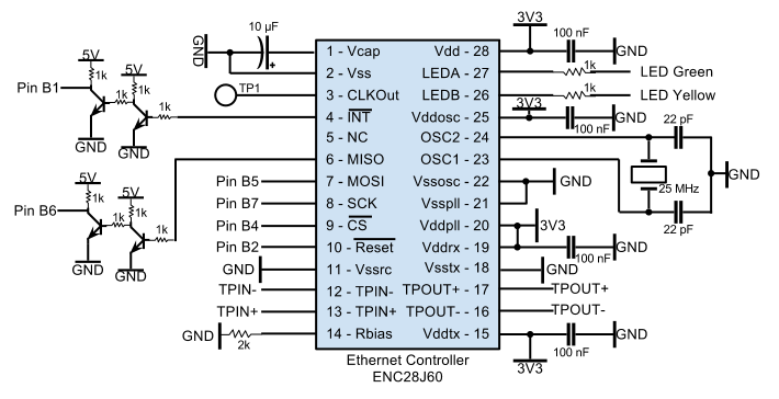
ENC28J60 Ethernet Chip Driver Module


This module is composed of exactly two header files and a source file. The purpose of this module is to define and implement all of the driver functions that are necessary to transmit and receive data packets from the local area network. The enc28j60.h header file defines different pin configurations for the board where the chip is 
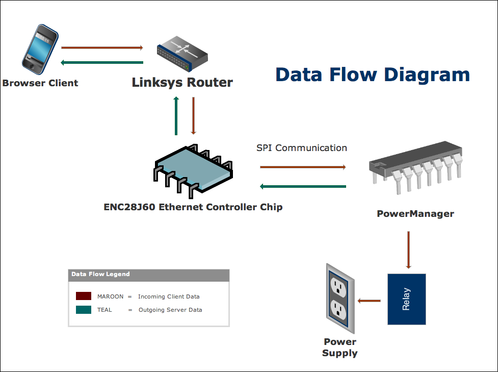
located.The driver abstracts away all of the complicated SPI communication between the MCU and the ENC28J60 board from other components that make up PowerManager. This makes writing and receiving packets into a matter of a few simple function calls. The enc28j60def.h header file defines all of the memory locations for the different bank registers, register bits, and SPI operation codes for the ethernet controller. The header file also defines where the in memory the start and stop address should be for its incoming/outgoing packet buffers. Most of this information is available in the official ENC28J60 design documentation.


Network Interface Card (NIC) Module


This module further simplifies the process of sending and receiving packets by abstracting away the ethernet driver details. Basically the NIC defines functions to initialize itself, send packets, and to poll the network for any new packets. We input packets by polling (through SPI) the chip's packet buffers for available information. The system's method handles the situation of importing packets that are too big for its buffer by simply dropping it. Once the packet has been received it stores it in a buffer for the uIP module to break up and process.


DHCPC Module


Dynamic host configuration protocol (DHCP) is a networking standard responsible for resolving host or domain names from IP addresses. IP addresses are generally difficult to remember and constantly changing. This makes host names extremely useful because they are able to map to a device's current IP address. A DHCP server (usually located on the LAN router) is responsible for resolving host name conflicts and is also responsible for updating every connected device's DHCP cache. This way IP addresses can change and the host mapping to it can remain persistent throughout its operation. The DHCPC module is responsible for checking if DHCP is available on the LAN. If so, it provides functions to handle DHCP initialization, requests, application calls, and configurations. This is all unnecessary if the user doesn't have a DHCP server available on their router or LAN. If this is the case then the user must manually assign a static hostname that doesn't conflict with other hostnames on the LAN.


uIP Module


The uIP module is a TCP/IP protocol stack designed to be as compact as possible for embedded devices like the ATMEGA644 MCU. It handles 
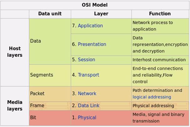
all of the mid level networking protocols as defined in the open systems interconnection model (OSI). To simplify communication in a network, the OSI standard hierarchically abstracts communication functions into logical layers. These layers help provide naming and routing information for a device to be able to send its packets to its correct destination.


HTTPD Module and Website CGI


PowerManager runs an HTTP web server over its TCP/IP stack. It is able to listen to HTTP requests and respond with an HTML web page. The HTTP web server lies on the application layer of the OSI model. When an HTTP request is received, the requested page is loaded from program memory. This page contains calls to Common Gateway Interface (CGI) functions; each CGI function call spawns a new protothread to run the function. In fact, the initial HTTP request is abstracted as its own CGI function call; the request loads a protothread which loads the page from memory and outputs it on an HTTP response buffer. Additional CGI function calls are made at this time and add to the HTTP response buffer. Once all CGI calls are made, the HTTP response buffer is sent to the client and displayed on their browser.

The PowerManager system contains three web pages: index.shtml, action.shtml, and 404.shtml. These web pages provide a GUI to view the current state of power flow in the power box and to control the state of power flow. The 404 page is displayed on default when a page that doesn't exist is requested. The index page displays the current state of power, and a button to toggle the power. The button makes a request to action.shtml with the requested action. If the action is "on", then HIGH is outputted on pin A7 to turn the relay on; if the action is "off" a LOW is outputted to turn the relay off. These actions guarantee that power will be at the requested state despite the initial state. As soon as the action is performed, an HTTP redirect is issued to return the user back to the index.shtml page to display the new state. A picture of the index.shtml page can be seen below in Figure 13.


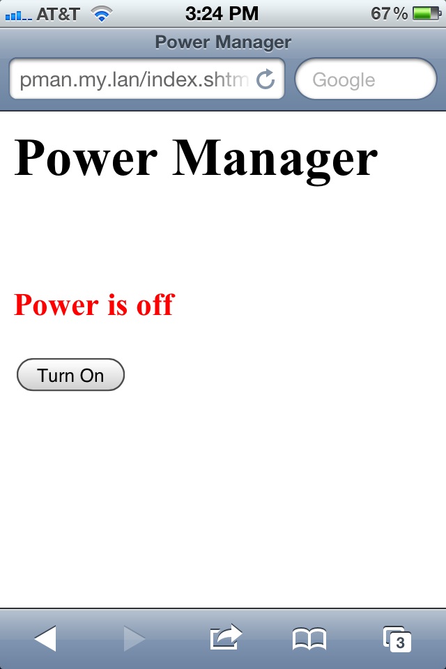
Figure 13 : PowerManager GUI


Miscellaneous Modules


These consist of the modules that we leveraged from other sources but didn't touch. This includes the modules that support protothreads, protosockets, timers, clocks, and local continuations. Protothreads are stack less threads that were designed for memory constrained embedded systems such as the ATMEGA644 MCU. Protosockets work with protothreads to help provide sockets for TCP to work. A socket is an abstraction that encapsulates a connection between a client and a server. It is used with the uIP module to provide a means for TCP to make reliable connections. The timer and clock modules serve to periodically signal PowerManager to perform its list of required tasks (e.g. ARP broadcasts and incoming packet buffer polling). The clock and timer modules are fundamental to PowerManager because events are handled synchronously using polling methods. They are also important because different tasks need to be performed in different time intervals. ARP broadcasts don't have to be done on every clock cycle because IP addresses don't generally change that frequently within networks. NIC polling on the other hand needs to be done more frequently because packets come in all the time. These different tasks must be managed and performed and different rates to ensure that everything goes smoothly. The local continuations module provide support for local continuations which are fundamental protothreads.


Conclusions

Testing & Results


The PowerManager system is effectively able to run IP, TCP, and HTTP stacks on an AtMega644 MCU and interface these layers with the physical layer on an ENC28J60 Ethernet controller through SPI. All of this is done given the memory and processing constraints of the AtMega644. To work with these constraints, all packets are limited to at most 400 bytes; anything more is instantly dropped when received and broken into multiple packets when transmitted. Additionally, the processing constraints and the fact that long wires were used meant that the SPI interface had to be run at a slow 1MHz.

Power turned out to be an issue with the system. On the ECE 4760 board, a regulator generates a 5V power signal. We use this signal to power the MCU, the Ethernet chip, the RJ45 jack, and the relay. The original regulator could not provide current to power all of these devices. Thus, a larger regulator was used instead. This larger regulator would get extremely hot and sometimes cut power, so a heat sink was added to stop this.

Since CGI is used to generate HTTP responses, the CGI function calls provide a serialization point for power control. Thus, multiple users can control the power at the same time; however, the MCU can only handle a few simultaneous connections at once, and is not meant for large scale use. A single client can effectively control power from the web-based GUI with very little delay, performing basically instantaneous power control.


Standards


PowerManager uses the following standards:
-NEMA 1-15 North America Electrical Outlet Standards
-ARP
-TCP
-IP v4
-DHCP
-HTTP
-CGI
-Ethernet
-RJ45 10/100 R-BTX
-SPI
-UART


Intellectual Property


The majority of the fundamental modules were based on other people's code. A lot of configuration was necessary to port the libraries to our environment, and we glued the libraries together with our own main PowerManager module. The majority of our code was based off the uhttpd-avr project. We want to give credit to Adam Dunkels, whose library we leveraged for PowerManager's uIP-1.0 minimalistic TCP/IP stack. We configured Dunkel's HTTPD module which PowerManager uses to communicate with client browsers on a local area network. This can be found on the same website as the uIP module. We also leveraged the uIP version 0.9 port to AVR ATmega32 with ENC28J60 which was written by Jonathan Granade (edi87 at fibertel.com.ar). We give credit to the original writers of all modules we used.

The ENC28J60 module was based off of designs from Olimex, MICROCHIP, NuElectronics, and TuxGraphics. These designs were ported to work with our ATMEGA644. We give these designers full credit for their work.

Finally, we do not plan on selling PowerManager or to make a profit from PowerManager. A patent for a similar product to PowerManager already exists, and can be found under patent #2011/0153108.

Ethical and Legal Considerations


We abide by the IEEE code of ethics so we aren't worried about ethical and legal issues. Although a significant amount of our code was based off other modules, we give credit to the authors for their work and reference the links for their original frameworks. Our source will be open source because all the code we leverage is also open source under the creative commons license.


Final Conclusions


PowerManager meets all of our goals initially set out. Power to standard electrical outlets, and thus to any plugged in device, is successfully controlled remotely through a web-based interface, served entirely on an AtMega644 and ENC28J60 Ethernet controller. Future iterations of this design would do everything much smaller on an integrated circuit and be placed inside of the power box rather than as a separate unit connected with an audio wire. Additionally, WiFi could be used instead of Ethernet to allow easier placement in one's home. Overall, we are happy with the final outcome of our project.

Considerations


We would like to thank Professor Bruce Land for working with us throughout the semester to finish this project and patiently answer all of our questions. We would also like to thank all of the TAs and course staff for ECE 4760 for working closely with us to debug our issues, answer our questions, and keep the lab open late for our benefit. Thank you all.

Appendix

List of Parts


DescriptionPart #Unit CostQuantityTotal
Ethernet ControllerENC28J60-I/SP-ND$3.861$3.86
3.3V RegulatorLD117-3.3$0.641$0.64
RJ45 Jack380-1106-ND$5.571$5.57
25 MHz CrystalCTX1158-ND$0.601$0.60
High Voltage RelayGA8-2B02From Lab1$0.00
Ferrite BeadFrom Lab1$0.00
100 nF CapacitorFrom Lab7$0.00
10 µF CapacitorFrom Lab2$0.00
22 pF CapacitorFrom Lab2$0.00
Misc. ResistorsFrom Lab15$0.00
NPN Transistors2N3904From Lab4$0.00
Audio PortsFrom Lab2$0.00
HeatsinkFrom Lab1$0.00
Electric Wall PlugFrom Home1$0.00
Electric Wall Socket$2.971$2.97
Electric Wall Switch$1.241$1.24
Electric PVC Box$1.971$1.97
Electric PVC Box Cover$1.191$1.19
Solder Board$2.501$2.50
Power Supply$5.001$5.00
ECE 4760 Custom PC Board$6.001$6.00
ECE 4760 Custom Serial Board$5.001$5.00
Serial ChipMax233CPP$7.001$7.00
Serial ConnectorRS232 Connctor$1.001$1.00
MicrocontrollerAtMega644$6.001$6.00
DIP Socket$0.502$1.00
Jumper Cables$1.006$6.00
SIP sockets/plugs$0.0580$4.00
TOTAL$61.54