A persistent of vision display that is able to receive images wirelessly to display in a two dimensional grid.
Project Soundbyte
Introduction top
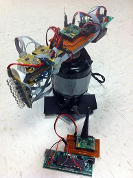
The purpose of this project is to design and to create a persistence of vision (POV) display. This display will allow users to upload an image to be displayed through wireless communication. A persistence of vision (POV) refers to the phenomenon of the human eye in which an afterimage exists for a brief time (10 ms). A POV display exploits this phenomena by spinning a one dimensional row of LED's through a two dimensional space at such a high frequency that a two dimensional display is visible. In our case, we created a cylindrical display by spinning a column of LED's around a central motor shaft (Figure 1). The rotational speed of the LED's is fast enough such that the human eye perceives a two dimensional image.
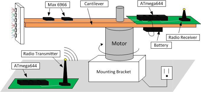
Figure 1. Hardware setup of POV display.
The overall design of this project can be grouped in the following three categories: electrical design, mechanical design, and software design. The most labor intensive portion of this project was the mechanical design. While the electrical schematics and software design appear trivial, integrating the hardware with an adept firmware proved to the biggest challenge of all. Mounting the electrical components onto the mechanical structure - i.e. the spinning arm - was also quite a challenge. As one can foresee, the nature of our mechanical design introduced various safety issues that we also had to take into consideration.
High Level Design top
The original idea for this project came from the brilliant mind of David Bjanes who has many projects in his project queue. The inspiration came when David saw a video of a similar POV display on Youtube.com. We approached Bruce Land, our professor, to discuss whether or not this would actually be a viable project idea. Next, we started brainstorming about the orientation of our POV display. Some ideas we had seen oriented the display on a propeller or circular clock, while others spun the display around a cylinder. We chose to build column style POV display in order to reduce the complexity of mapping a Cartesian coordinate system (found in most rectangular displays) to a polar coordinate system.
The logic behind our project is very straightforward. Our software must calculate the rotations per minute (RPM) and the release and deadline times which set the time duration to display each "pixel" of the display (explained in software section). From a high level design, we simply measure the period of each rotation, divide time the cantilever takes to rotate through that section by the number pixels we want to display and then calculate the amount of time each pixel occupies during the rotation. By turning on a light emitting diode (LED) for just that duration of time, we can then display the pixel. Thus, we've mapped the entire display area to a 14 by 90 matrix where each element in the matrix represents a pixel that can have any red, green, and blue (RGB) value.
The nature of our design allows the software and hardware design to be independent of each other in terms of tradeoffs. The more robust our hardware becomes (i.e. tying down wires and securing boards), the safer our project becomes. The more robust we make our software (i.e. robust state machine and LED mapping), the more optimized and error free our project becomes. The only case where our decisions about which hardware we used affected software decisions was when we ran into memory issues in RAM when the resolution of our display grew too large. On our microcontroller, the ATmega644, in order to increase the resolution of the display (i.e. to store a larger matrix which contained the pixel information), we would need additional memory modules to provide this functionality. We decided against this due to time and space constraints on the arm itself.
Our project uses two standards, serial peripheral interface (SPI) and IEEE 802.11 for our wireless radio communication. The standard for SPI consists of a 4-wire serial bus that allows a master/slave communication mode. The wires are the following:
- SCLK: serial clock (output from master)
- MOSI: master output, slave input (output from master)
- MISO: master input, slave output (output from slave)
- SS: slave select (output from master)
The IEEE 802.11 standard is for the wireless radio which is controlled by the FCC regulations for radio frequency devices. This regulation can be found in Title 47 part 15 section 243 on the FCC regulations website. Since our radio transceiver was designed within the FCC regulations, it meets all the specifications noted in the section, especially the 500 microvolts/meter at 30 meters.
Our project does not include any existing patents, copyrights, or trademarks. We've designed all the hardware from scratch and all the software is our original work with some assistance from classmates and Professor Land.
Design top
Electrical Design
The electrical components used are:
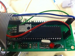
Figure 2. Onboard ATmega644 microcontroller.
- On-board ATmega644 microcontroller (on development board)
- Stationary ATmega644 microcontroller (on development board)
- 5 MAX 6966 controller chips
- 14 RGB LEDs
- 1 9V battery
- 1 pair of IR transmitter and receiver
- 2 WI.232FHSS-25-R radio transceivers from Radiotronix
- 2 WI.232FHSS-25-FCC-R break out boards from Radiotronix
- LP2951 Linear Regulator
- LM340-15 Linear Regulator
- Various Resistors and capacitors
- Various wires and header pins
There are two main electrical designs to this project, the onboard (attached to spinning arm) system and the stationary system. The primary purpose of the onboard is to actually turn on and off the LED's based on a two dimensional matrix (further described in the software section). The onboard circuit consists of an ATmega644 (Figure 2) microcontroller which is powered by a 9V battery (also onboard). In order to turn on the LEDs, the microcontroller will act as an SPI master and the MAX 6966 will act as SPI slaves. The master, the microcontroller, will communicate to the slave chips via the SPI bus. It will send serial commands to write the registers on the MAX6966 chips. On the slave end, the target MAX 6966 chip will receive an 4-bit value that it will correspond to a PWM duty cycle outputting on specific port connected to a target LED. The onboard circuit schematic shows all five MAX 6966 chips controlling 14 RGB (red, blue, and green) LED's. The max chips are powered by a 3V3 regulator from the 5V rail from the microcontroller and the LED's will be powered from that rail as well. Also, the onboard microcontroller will be calculating the RPM (Rotations per Minute) at every rotation to adjust the display depending on how fast the arm is spinning. Lastly, the onboard microcontroller will communicate with the stationary microcontroller via radio units.
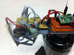
Figure 3. Onboard MAX 6966 chips that control the LEDs.
Each MAX6966 chip (Figure 3) has 10 output pins and an SPI input bus. Since each LED is controlled by 3 pins, each MAX6966 chip can control 3 LED's. The SPI control bus comes from the microcontroller (master) and chooses which MAX 6966 chip (slave) to talk with and control pin outputs. Each pin on the MAX6966 chip can be chosen to turn on or off a color for a specific LED. Since we have 14 LED's (needing 42 driver pins), we decided to use 5 MAX6966 chips (corresponding to 50 outputs), each with its own chip select.
To collect the RPM data needed for our timing calculations, we have the microcontroller connected to an infrared (IR) circuit board. This circuit consists of an IR transmitter and receiver which face downwards. Each time the circuit board passes by the white piece of paper, it will send a signal to the microcontroller to trigger an interrupt to calculate the rotation period.
The wireless transceivers used to send images are connected to their respective microcontroller boards using the UART TX and RX pins. The RX and TX pins on the wireless transceiver are connected to their counterparts TX and RX, respectively, on the microcontroller.
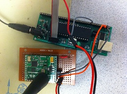
Figure 4. Stationary transmitter connected to computer.
All of the power needed by the electrical components (not including the microcontroller) is from the VCC from the microcontroller. In order to allow the microcontroller to provide enough current to power all 14 LEDs, 5 MAX 6966 chips, IR circuit, and wireless transceiver, we have a high current (1A) LM340-15 linear regulator on the microcontroller to limit the 9V from the battery to 5V. Furthermore, since the MAX 6966 chips take 3.3V, we have an LP2951 linear regulator to limit the 5V VCC output from the microcontroller to 3.3V.
The primary function of the stationary circuit is to act as the user interface so that the user can upload whatever image to be displayed (Figure 4). Another function of the stationary circuit is to select different functions for the onboard board to perform such as animations, clearing the display, etc.
Since our motor is an AC motor that spins at 1,600 RPM as soon as it is plugged into the wall socket, this is too fast for our application. Thus, to reduce the speed and to prevent the motor from going from 0 to 1,600 RPM instantly, we are using a variable AC adapter. It is actually a light dimmer from Lutron Electronics, but it is essentially a variable AC, and it has a dial for choosing how much amplitude we want to give to the motor. This allowed us to perform safer tests, without worrying about pieces flying off of the spinning arm.
Hardware Design
- Bodine Electric Company AC motor
- Base support plate
- Vertical support plate
- Plexiglas support arm
- Plastic arm (for LED)
- Several 3M dual locks
- Electrical tape
- Hot glue
- Various size screws
The main components of our hardware design is an AC motor, a mounting bracket for the motor, and the spinning arm which is comprised of a Plexiglas piece and a plastic piece. The Plexiglas acts as the main support for the arm and is connected to the spinning shaft of the motor, while the plastic piece has for the 90 degree bend at one end to provide a platform for mounting the LED's.
Our AC motor does not have any self-supporting component to stand upright. Thus, we have built a mounting bracket that will hold to make sure the motor is standing upright. The bracket consists of the base piece and the vertical support piece. Both pieces are approximately ¼ of an inch thick. The vertical support piece is connected to the base piece at a 90 degree angle with two size 8-32 screws. Next, the motor is attached to the vertical support piece with four size 10-32 screws in a square orientation. The four tapped screw sockets on the motor was initially already there, so we had to just drill four holes in the vertical support that are lined up with the provided sockets on the motor. This mounting bracket provides great stability while the motor is spinning at high rates. Load balancing of the spinning cantilever is the main reason for the stability during spinning. As an addition precaution , the user should clamped the bracket to a table during the spinning.
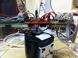
Figure 5. Spinning arm attatched to rotor.
For the spinning arm, a piece of Plexiglas 1/4 of an inch wide and 1/2 foot long is attached to the spinning shaft of the motor. This shaft is approximately a size N hole with a small flat edge. In order to secure the Plexiglas firmly to the shaft without it sliding along the shaft in any way, we drilled a hole size that is just a bit smaller than size N (to make it a very tight fit), and drilled a small hole on the side to insert a set screw that will push against the flat edge. We decided to use Plexiglas because it is a strong yet light material. Lastly, a thin plastic piece was bent at 90 degrees near one end and attached to the Plexiglas. We are using this plastic piece mostly because it is easily bendable while also light.
In order to make sure we don't get too much wobbling when spinning at high rates, we positioned the electrical components on the spinning arm to provide good counterbalance on both sides (Figure 5).
Software Design
The software design of this project is relatively simple. We are running three tasks; task1 to record and calculate the current RPM at every revolution, task2 to write the appropriate data (based on matrix) to the respective MAX6966 chip port via SPI, and task3 to run the animations. The frequency of task2 being executed depends on the measured RPM values by setting the release and deadline to the amount of time per "segment" (each column in our matrix). Each "pixel" of the image is represented by one element in the matrix. Currently, we have a 14x90 matrix displaying only on half of a circle, but it is possible to expand the resolution in the future. Furthermore, each element in the matrix is a 16 bit number where the first 4 bits are for the red value, the next 4 are for the green value, and the last 4 bits are for the blue value of an LED. These 4 bit values are mapped to 8 bit values to actually set the intensity level of the LED's. The main difficulty of the software was to setup the SPI communication between the microcontroller and the MAX6966 chips.
The MAX6966 has 10 I/O ports, each capable of outputting an 8-bit PWM signal. Each port is controlled by registers onboard the chip. The SPI bus is used to communicate with the MAX6966 and set both the explicit registers which control the ports and the implicit registers which control the state of the chip (power up sequences, shutdown mode, run modes, etc). The MAX6966 is a current sync which means to turn on an LED, we short the Port pin to ground completing the circuit and turning on the common anode RGB LED. To program the chip, we send commands to the register to allow maximum current draw through each pin (20ma) and set every port high (LED's are wired low logic). We put the chip in run mode and then we are ready to set the outputs of every pin and control three RGB LED's (per MAX6966 chip).
In order to display anything, a transmitter must send pixels to the onboard receiver which will then populate the display matrix in the microcontroller with the sent pixels. Thus, there are two components: the transmitter code and the receiver code. The transmitter code is very straightforward; we transmit each pixel at a time as a packet. Before we send each packet, we must send a SYNC byte and then an ADDR byte. The SYNC byte will sync the transmitter and the receiver, and the ADDR byte will let the receiver receive data only from a transmitter with that expected ADDR byte. After these 2 bytes are sent, we send the column and row byte. Next, we break the 16 bit data into 3 bytes that contain the first 3 nibbles of the 16 bit data and send them across. Lastly, we send an antisync byte to let the receiver know that it has finished sending data.
The code for the receiver is a bit more complicated. It involves a state machine with states WAIT_SYNC, WAIT_ADDR, and WAIT_DATA. State WAIT_SYNC waits for the SYNC byte from the transmitter and once it sees that, it goes to the WAIT_ADDR state. State WAIT_ADDR waits for the ADDR byte and when it sees it, it goes to the WAIT_DATA state. Otherwise, it goes back to WAIT_SYNC state. In WAIT_DATA state, the processor waits to get data for the column and row byte and then the data bytes. After all the data bytes and the antisync byte are received, the state machine will proceed to recompile the individual bytes back to a 16 bit data and put it in the matrix element at the received row and column.
We have also added animations to our project. This specific animation was hardcoded to move the 'S' in "SEXY" back and forth repeatedly. We did this by turning off the LED's in the previous location of 'S' and then turn on the LED's in the next location of 'S'. As of now, our animation code remains to be hardcoded and a possible extension for this project can be a more user-interactive animation.
Testing top
Hardware Testing
The structural components of the design were very straightforward; we needed a design that would allow the motor to stand upright instead of lying down. Thus, we eventually came up with the L shaped mounting structure. The actually machining process for this piece took time since neither my partner nor I have had much machining practice. However, it was just a matter of drilling two holes through the vertical plate which lined up with the two holes in the base plate. The important step was to tap the base plate, but use a body drill for the vertical plate for the same hole size. This allows the screw to push the vertical plate against the base plate tightly. Our original efforts had both holes in the vertical and base plate tapped, causing the joint to be very weakly attached. After the holes on the vertical plate were drilled with the body drill, the joint became very strong.
After attaching the spinning arm (the last structural component), we tested spinning the motor. The first test proved that it was necessary to clamp the mount to the table while spinning. This was because since the motor was just an AC motor with the power outlet as the power source, the motor settings were either off or on at maximum speed. Even with the mount clamped down, when the motor was turned on, the motor would shake the entire bench. This was clearly too dangerous to actually test with any electrical devices attached to the arm. To allow a variable speed for the motor, we used a light dimmer that is basically just a variable AC controller. This allows us to adjust the speed of the motor progressively, allowing us to test with much lower RPM's.
Next, the electrical components were added to the arm. The electrical components that we used in our initial light test consisted of a 9V battery, the target board, the IR sensor, a through-hole board with one MAX6966 chip, and another through-hole board with three LED's. Aside from the target board, all the other components were attached on one end of the arm. This was the only viable option because the spinning arm was connected to the shaft at just one end of the arm, so there was no space to add counterweights. Thus, when we started spinning at a slow 200 RPM's, the system became very unstable and started to shake the table. At this slow speed, however, it was enough to show a proof of concept because we can still discern the image. Once this was done successfully, we began to expand our design to include 14 LED's and to improve load balancing.
With the 14 LED design, we were also able to move the bottom Plexiglas piece more to the other side to allow space to put the microcontroller and the battery. This design allows us to spin the arm at near maximum speed of the motor without any signs of structural instability. The only main issue that we had left was to figure out the wiring of all the electrical components. Since we were using 14 LED's, that means we needed five MAX 6966 chips, mounted on two through-hole boards. Once everything was connected, insulated, and tested, it was turn to test the software.
Software Testing
The first piece of code that was written and tested was the SPI code. Once this was tested and working successfully, we were able to write the code based on TRT operating system.
Next, we added the code to measure the RPM of the system. Amazingly, our code worked without any major bugs with the three LED's. Our biggest concern was that TRT could possibly jump to another task while in the middle of writing SPI to one of the chips. However, this proved to not be a problem after testing. One issue that was not considered at this point was displaying all three colors for each LED. For the sake of quick testing, our matrix consisted only of either on or off for each LED, where on is just max intensity in red color. Our next expansion design includes the use of all the colors for each pixel.
A major problem in the updated code for 14 LED's was a problem with having enough memory. Creating an uint32_t matrix with size 14 by 180 causes us to use four times the amount of memory that we have. Thus, we proceeded to reducing the number of column pixels to 90 while keeping the resolution the same. This just meant cutting our display to just half the circle instead of the entire circle. Also, instead of using uint32_t, which is 32 bits, we used uint16_t and use 4 bits for intensity for each LED color. These 4 bits will then be logarithmic scaled to an 8 bit number.
Another major problem we encountered was intermittent receiver failure. However, resetting power on both the receiver and the transmitter would fix the problem. Other bugs such as turning off the transmitter while it's in the middle of sending data to the receiver would also cause the receiver to freeze (the LED's still displayed the image right before it froze since the MAX chips control the LED's, thus, hard to debug). We were able to narrow the problem down to our receiver's state machine, since it had several holes that could cause the onboard microcontroller to freeze. For example, turning off the transmitter in the middle of transmitting could leave the receiver stuck in the WAIT_DATA state since it never got the antisync byte. Another problem was that we did not check to see if row and col were within our useable limits. Thus, if we were to receive mixed up data and set col to a number greater than 89, then our code would crash because it would try to access an index that's out of bounds (we have 90 columns).
Results top
Our project met all of our requirements laid out in our proposal. We were successfully able to spin a one dimensional array of LED's through a two dimensional space (a cylinder) at a high enough frequency such that a full 14x90 pixel RGB display can be seen. We can successfully communicate wirelessly to the spinning onboard microcontroller to update the display and change any of the pixels at any time.
Our onboard system was spun around 500 rpm. This was definitely fast enough for the human eye to retain the information displayed, but it did present a definite flicker to the eye. The refresh rate (of spinning the LED's) is obvious. However, by turning out the lights, or displaying in a darkened room, we can help reduce the flicker and increase the intensity of the display.
Safety was a concern for our project. Spinning essentially a blade at 500rpm is dangerous enough, and we were mounting several PCB boards, a 9V battery, a transceiver and a row of LED's to our spinning blade. We began by mounting each of the components on the cantilever with electrical tape. This unfortunately did not let us have easy access to the hardware for testing and debugging purposes and we could not remove the hardware easily for upgrades, modifications or repairs. Removing the tape could produce voltage spikes as high as 5000V across our circuits so at the risk of blowing out chips and damaging the hardware, we carefully removed the tape and abandoned this method of attaching our hardware to the cantilever. We used Dual Lock, a 3M product similar to Velcro, which has a high coefficient of friction and would allow us to detach our boards for repairs and modifications as well has hold them on while the intense g forces threaten to hurl them off the spinning cantilever. As a precaution, we wore safety glasses to protect our eyes should anything happen. Before each time we turned on our motor, we checked each board to ensure it was securely fastened. We also used variable AC speed controller to slowly ramp up the speed. This helped reduce the severe acceleration (both from spinning and quickly increasing the speed).
We did use the radio transceivers identical to those several groups in the lab. We prevented interference from other radio communication by adding a fixed address in the beginning of the packet structure. Both the receiver and the transmitter had this fixed address hardcoded and checked each packet to ensure they contained it. If the packet had this address, we could be confident that this was our packet we received, if a different address was read, we could be sure it was someone else's packet we have accidently received.
In terms of a user interface, the method for sending pixels at this point in time must be done manually. Commands must be sent to every pixel detailing exactly what color to display. The transmitter also needs to be programmed each time a new packet or group of packets needs to be transmitted. This leads a cumbersome user interface, since the user must be familiar with programming the microcontroller and familiar with our code. In the future, we would like to connect the UART (instead of using the UART to send the data to the transceiver) to the computer, and connect the transmitter to a manually written UART on a separate I/O pin. This would allow serial communication between the computer and the microcontroller, opening the possibility for all sorts of user interfaces to be built. One idea for future exploration would the writing a program which parses a *.bmp or *.jpg and sends those across the UART to the microcontroller to be then transmitted via radio to the onboard microcontroller and displayed on the LED's.
Conclusions top
While we met all the specifications detailed in our proposal and pleased with the performance we achieved, we have many plans for building on the initial foundation and continuing with additional refinement of the project. We succeeded in building a proof of concept, on the test bench, a rugged design; however, our project is only a foundation on while many other interesting projects could be built.
Improvements and areas of future exploration include upgrading to a faster motor to eliminate the "refresh" or blinking of the display. This would involve some major modifications to the design including figuring a better way to fix the PCB boards and battery to the spinning cantilever. Perhaps, it would be better to just design our own PCB in which all the components would be surface mounted. This would eliminate much of the heavy wires and extra PCB board contributing to the weight of the arm as well as drastically reducing the space (since every component would be surface mount) needed to contain all the components. Reducing size and weight would also make it easier to spin the cantilever faster.
The RGB LED's have done a great job, however I would like to either get defused LED's (we used a clear LED casing) or LED's in which each color diode in the LED housing was closer together. Sometimes, depending on the viewing angle, it can be difficult to tell that two different color diodes in the same LED aren't two side by side LED's.
In conclusion, this project really demonstrated competence combining a difficult integration of the mechanical and electrical systems to build a persistence of vision display. We built a general standalone system which can receive input from any device wirelessly to print out a display based on the pixel information received. We demonstrated this by connecting with the alphabet character recognition system. The onboard system is a fully contained system, capable of outputting the display at varying RPM speeds and not carrying about what system interfaces with it as long it follows a standardized wireless protocol developed by us. This project also has so much room to explore further exciting developments and additions to the many devices with which it could interface.
Intellectual Property Considerations
We would like to thank Seonwoo Lee (sl787) for providing us with example code for the transceivers. We used his base code example when learning the protocol for setting up the UART and transceivers and as a test to confirm the transceivers worked. We then built our own packet structure and designed the transmission wirelessly from the stationary to the spinning onboard system to best suit our needs (transmit the matrix of pixels as fast as possible while still maintaining the integrity of the data).
We would like to thank Bruce Land for brainstorming ideas about our project, specifically: his assistance in getting the SPI bus to work, insight into attaching the modules on the spinning arm, use of his lab and its resources (including supplying us with a free motor and two transceivers) and his vast collection of knowledge - which he readily shared - on nearly every topic which our project covered. His lectures on microcontrollers and proper coding practices were invaluable.
We would like to thank Pavel Vasilev for his assistance in general coding questions and general lab knowledge which he imparted to us through many hours of explanation and examples.
We would like to thank Joe from the Rhodes Hall machine shop for helping us design and build the hardware components for the motor.
We did not reverse engineer any patented or trademarked designs; however, our inspiration came from watching YouTube clips of others who have sought to achieve the same thing we did. We did not contact anyone to find out how they went about solving this particular problem or see any of their posted solutions, in so far as to see their video demos on Youtube.com.
In partnering with Stephen Wu and Justin Churchill in their project of alphabet character recognition from touchpad interface, we are interested in pursuing, alongside them, a patent for a persistence of vision display receiving real time touch screen input. We gave them the packet protocol for sending information to the update the display, and they added the functionality to their project to send the data which they were already printing to an LCD display, to our POV display instead. They also added the functionality to draw freeform and send whatever picture is drawn on the touchpad, to our POV display. If a patent idea is palatable, a paper might also come from a combination of the projects.
Ethical Considerations
According to the IEEE Code of Ethics, we strove to do our best to uphold and abide by the spirit and letter of the code. Taking into consideration the safety concerns mentioned above, we were careful during our testing phases to not endanger other members in the lab and made sure that anyone in close proximity to our project wore safety glasses as well. We did not consciously or unconsciously pirate anyone's intellectual ideas and credited all who helped us, from those who provided insightful feedback into our project to those who helped debug our code and build our hardware. We eagerly sought the advice of our TA and professor on nearly every aspect of the project. We strove to help those who worked alongside us by doing everything from answering hardware questions about soldering to being a second pair of eyes debugging stubborn programs whenever possible. We have written accurately about our project, not omitting any details of our development or testing phases. We have presented our project in an objective light as much as possible and strove to give the reader all the information necessary to judge it for necessary safety considerations. We have upheld all laws known to us, specifically those pertaining to the FCC regulations on transmission of data via radios. In good faith, I can confidently say we have upheld the IEEE Code of Ethics.
Legal Considerations
We used a non-licensed transmitter which complies with FCC regulations for small, low power transmitters. Our transmitters have FCC labels identifying their compliance with FCC regulations. Our transmitters are not continuously transmitting and are not modified to operate in a range outside of the frequencies or power levels for which they are classified.
Appendix top
MAX6966 Board Schematic
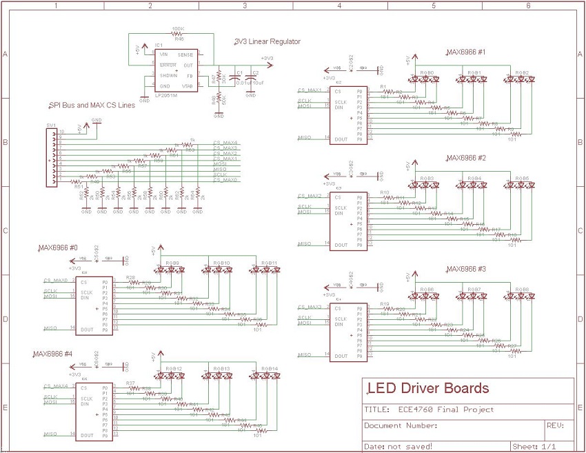
Schematic of the MAX6966 board connected to the LEDs.
Microcontroller and RF Schematic
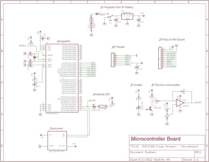
Schematic of the microcontroller with RF and radio transceiver circuits.
Source Code
Download the main source code here
Download the transmitter source code here
Budget List
| Description | Vendor | Number Ordered | Unit Price ($) | Total Price ($) |
|---|---|---|---|---|
| -- | -- | -- | Total Expenditures | 70.39 |
| 100 RGB LEDs | Parts Express | 0.14 | 19.99 | 2.79 |
| Motor | Scrounged | 1 | Free | 0.00 |
| Transceiver | Lab | 2 | Free | 0.00 |
| MAX6966 | MAXIM | 5 | Free Samples | 0.00 |
| Target Board | Lab | 2 | 15.00 | 30.00 |
| 2" Through-hole Board | Lab | 4 | 1.00 | 4.00 |
| Female PIN headers | Lab | 282 | 0.05 | 14.10 |
| 0.1" Headers | Lab | 20 | 0.05 | 1.00 |
| 9V Cable | Lab | 1 | Free | 0.00 |
| Jumper Cables | Lab | 8 | 1.00 | 8.00 |
| 6" Through-hole Board | Lab | 1 | 1.00 | 1.00 |
| Dual Lock | Campus Store | 0.50 | 15.00 | 7.50 |
| Metal Mounting Bracket | Scrounged | 1 | Free | 0.00 |
| Wires | Lab | Many | Free | 0.00 |
| Electrical Tape | Lab | Many | Free | 0.00 |
| Ribbon Cable | Lab | 15 | Free | 0.00 |
| Plastic Cantilever | Lab | 2 | Free | 0.00 |
| Resistors/Capacitors | Lab | Many | Free | 0.00 |
| LM340-15 | Lab | 1 | Free | 0.00 |
| LP2951 | Lab | 1 | Free | 0.00 |
| Jumpers | Lab | 2 | 1.00 | 2.00 |
Division of Labor
David designed most of the electrical components and sodered them together as well as attaching them to the spinning arm. If there was any sort of hardware fixing to be done, David would be able to fix it very quickly. David was also responsible for developing the SPI communication protocol to talk to the MAX 6966 chips as well as contributions throughout the rest of the software.
Jun designed and built the mounting bracket for the motor as well as the spinning arm for the motor. He was also responsible for designing most of the current software and processing algorithms as well as troubleshooting much of the software.
References
Datasheet for RK-WI232FHSS-25-FCC-R is here
Datasheet for WI232FHSS-250-R_25-R is here
Datasheet for ATmega644 is here
Datasheet for MAX6966 is here
Datasheet for LM340-15 is here
Datasheet for LP2951 is here
ECE4760 Course Website is here