"Keep track of exercise even when walking to class! "
Our final project for ECE 4760 provides a simple but effective exercise monitoring system of the user's walk or run. With an increase of the number of health conscious individuals hoping to remain fit, we designed a system that allows the user to keep track of his or her total number steps, current speed, and total distance in both real time and with a data logging system. This is especially useful for any students who are concerned with how much exercise they are getting by simply going to class!
Using the ATmega644 microcontroller, we perform the necessary communications between the accelerometer which obtains the data, the LCD screen which displays real time data, and the SD card which stores the data. The logged data on the SD card can then be inserted into a user PC with MATLAB to plot the relevant exercise waveforms.
Although the short 5-week project is still very clearly in prototyping stage, it provides the groundwork and proof of concept for reasonably accurate distance and speed calculations using two simple accelerometers.
System Level Design
Rationale | Background Math | Logical Structure | Hardware/Software Tradeoffs | Applicable Standards | Existing Patents Copyrights and TrademarksRationale
Our project inspiration came from a previous project both of us had worked on a previous year. At that time, we had both worked on separate projects involving a simple Pedometer using a MSP430 microcontroller. Unfortunately, due to time constraints and hardware failures, we were unable to complete the project. Unwilling to accept defeat, we attempted the project again, but with the intention of providing greater functionality, better user interface, and a working final product. While we understood that many smartphone apps provide a similar functionality, we wanted to see if we could provide comparable functionality without all the need for fancy hardware and expensive data plan.
From the beginning, we decided to use the ADXL345 digital 3-axis accelerometer, not only because of its expansive functionality and zero cost (due to borrowing the part), but also because we had extensive familiarity with the part which would reduce the start-up design time. Initially we had planned on using the built in interrupts and threshold functionality found on the ADXL345, but after determining that we would be using the Tiny Real Time (hereafter called TRT) multitasking kernel, we found that it was easier to poll the accelerometer for data.
Apart from data acquisition, our exercise measurement system provides two forms of data display and analysis. The more simple of the two involves a simple 16x2 character LCD screen. It provides all the necessary information to the user while the user is walking or running. This includes the number of steps taken, average speed, and total distance using the dead reckoning navigation technique. While we had hoped to improve upon our distance and velocity calculations using a GPS system as a potential improvement, we decided against the addition due to both limited time and the inability to use GPS indoors, where many potential walkers would be using the device.
Finally, our secondary data display and analysis device involves using the common SD card to log user data and plot them on MATLAB. This provides more than simply the above mentioned metrics displayed on the LCD but also the raw acceleration data before much of the noise canceling is performed. This allows for the more in-depth and curious user to look at the slight differences in walking style which may be found in persons suffering from anything ranging from a sprained ankle to more serious medical conditions. As a plus, the user can keep a record of all of his or her exercises to track changes over time.
Background Math
This project does not have conceptually difficult math. There are two main calculations that are taking place: detecting a step and determining distance. We tried a couple different methods of calculations, which can be read in Appendix B, but we want to focus on what's working in our final code.
When we break down what constitutes a step, we can focus on a single, critical event: the cessation of a foot's downward motion due to collision with some surface. From mechanics, we know that any change in an object's momentum is either due to an impulse from this collision. We can then say the following is valid:
$$\delta\rho = m\delta v = Ft$$
Furthermore, we know that the force applied looks like a spike. This external force is directly proportional to acceleration, per Newton's Second Law. Now, the implication of this is clear - by placing an accelerometer on each foot, we should be able to record these spikes directly from acceleration data and correlate them to a step.
To determine what a step is, we use a dynamic envelope threshold based on a running average of the acceleration data and call a step a point at which the acceleration exceeds this threshold. By implementing this, we can accomplish a few things - we reasonably assume that the spike will exceed the running average by a decent margin and we allow the threshold to change, which allows for sensing softer steps and prevents from overcounting steps. Even then, there will be instances when the acceleration spikes above the threshold due to noise and could be counted as a step in error.
To prevent this double counting, we add a simple timer. Depending on the pace someone takes, we can expect a minimum amount of time to pass between steps - logically, the faster someone runs, the quicker we can expect these steps. Arbitrarily, we impose two different values for this minimum time delay, 400 ms at a walking pace and 200 ms for a brisk pace and running. To determine which value to use when, we apply a bit more physics.
A logical assumption that can be verified is that as a person speeds up their pace, their foot will be travelling down with a greater velocity before stopping, which means a larger spike over a quicker time. If we take the acceleration and take the differentials to find the jerk, we will observe that the over time, a faster pace has a distinctly larger moving average of jerk. We set compare this average jerk to an arbitrary threshold to determine whether a larger or smaller delay is to be used.
Our method of determining distance is dependent on having accurate step data. Assuming we have accurate steps, we can use two parameters to determine a rough speed - pace or the rate of stepping, and the step length. Quite simply, the rough velocity will be the pace multiplied by the step length. This makes intuitive sense - if I take 4 steps a second and each step is about a half a foot, one can expect to travel 2 feet in a second. We now have a measure of speed, and we can easily integrate to find a distance.
For both essential components, there is a considerable amount of arbitrary values that are set - number of samples to use for the running average, different thresholds, the strides, etc. Almost all of these are derived from running numerous iterations of the code, tweaking parameters and attempting to see what worked best.
Logical Structure
The structure of this design centers around the ATmega644 and its three peripherals, namely the accelerometer, LCD screen, and SD card reader with MATLAB plotting. The peripherals can be divided into two broad categories of function: data input, and data output. As can be deduced, the accelerometer system was used for data acquisition, and the LCD screen and SD card were used to log or present data that would be meaningful for the user in real time or for future use.
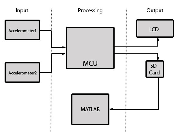
Block Diagram
Upon startup of the program, operation of the system proceeds as follows:
- User positions body in normal walking orientation
- User presses a button to initialize accelerometer calibration and waits a few seconds
- User proceeds about normal activities while logging data
- User presses the button again to stop logging data and close log file ***optional***
- User may load SD card into PC running MATLAB
- User loads MATLAB and changes the working directory to the SD card
- User runs the MATLAB script
Hardware/Software Tradeoffs
The hardware logical design is straightforward, consisting of the main microcontroller communicating with its 3 peripherals (LCD, accelerometers, SD card). Since none of these peripherals are extremely expensive or computation heavy, the main difficulty lay in software tradeoffs. Since the entire program was run using the TRT scheduler, how much time before the next release and deadline for each task was important in determining the tradeoffs between user experience and total data logged.
Since the both the accelerometers and SD card run on the SPI bus, their rate depended solely on the SPI clock speed. This determined how quickly a single byte of data was transmitted across the SPI bus from master (MCU) to slave (peripherals) and back. The sclk is run at 4MHz because a clock divider of 4 was used on the MCU which was also less than 5MHz, the maximum clock speed on the ADXL345. 4 MHz is twice the minimum required speed to run the accelerometer at 3200Hz maximum output rate. Since human walking applications do not require the accelerometer to acquire new data so quickly, the default output rate of 100Hz is more than enough.
The rate at which the MCU reads the SPI bus for new data is actually the rate at which data is received from the accelerometer and this rate heavily depends on the load of the scheduler and whether other processes have passed or missed its deadlines. The sample data function currently averages over 4 data points, which reads the registers from the accelerometer at rate 800Hz. The greater this sampling rate, the finer the logged data. At a high enough sampling rate however, the LCD interface needs to display slower and will affect the user experience because of slow refresh rates.
The SD card also operates on the same SPI bus as the accelerometer and writes to the SD card at the same sclock speed. However, during the disk initialize protocol, the SPI clock must be reduced to a lower speed as it writes 0xFF to the SPI buffer to initialize. If the clock speed is too fast, not enough time may be given to the sclock to clear the buffer and properly initialize the disk.
Applicable Standards
Our design does not have a lot of interactions with the typical standards. This iteration of the project is wired, so we don't have to worry about any wireless or radio communication standards that other projects cite. For software, the ANSI C protocol is already met through the use of the GCC compiler in class and the implemented FATFS protocol developed by ChaN. We use the SPI protocol developed by Motorola throughout the project - as the Mega644 MCU, ADXL345 accelerometer, and SD card already comply with SPI protocol, there's little we can do to violate this protocol and have an operational project. While we didn't need to do anything concerning the actual concerning the SD card hardware, the cards complied with the Secure Digital formatting standard.
Searching through IEEE standards and ISO returns one active project that could possibly be a standard we need to consider: P11073-10441 - IEEE Draft Standard for Health Informatics - Personal Health Device Communication - Part 10441: Device Specialization - Cardiovascular Fitness and Activity Monitor. At the moment, it's only an active project, not a standard, and we don't have information as to what the specific standard entails. However, if this is published and becomes a standard, we would need to see if our device is included. We don't directly measure any biometrics, but our designed application is in essence an activity monitor, so we need to be careful with this standard. Simultaneously, the description of the standard in development could render our above concern moot - the standard speaks to defining a normative means of communication between devices and what they define as managers (cell phones, computers, etc.) Our current design does not directly interact with other devices and instead relies on a more primitive "store data and look at it later". So again, while we will probably monitor this standard for the sake of remaining in good standing, it's doubtful that standard will even be applicable.
Existing Patents Copyrights and Trademarks
We're certain that a patent on the concept of the pedometer exists in some form, and there are probably many that interface stepping with distance calculations.
One paper in particular that is of great relevance in terms of copyright is an article written for Analog Dialogue, which is a magazine from Analog Devices.
At the time we found this article, we had already found a relatively accurate way of determining a step and we were writing code to improve the accuracy for different speeds. This article presents an alternate method of deriving the occurrence of a step, but discusses the approximate speeds related to the calculated paces.
So our concept is not exactly novel. However, we'll talk with Bruce - as far as we could see, few people used two accelerometers on the feet or used a running average threshold. Of course, our rationale is that this would be the foundation of a much larger sensor network, whereas other projects just want a simple pedometer.
We use SD and microSD cards, which already have patents on them. If we wanted to pursue patents, we need to look into how patented products are implemented and how royalty fees check out.
Hardware Design
Mega644 Board | Voltage Regulator | ADXL345 | SD Card Reader | Voltage Level Considerations | LCD | Button Setup | Overall SetupThis section will breakdown the hardware components of our project and discuss any details and decisions made. Datasheets will be referenced often, and the appendices will contain links to the relevant components. When possible, we will provide commentary on the usage of particular parts and insights for future projects.
Our schematics can be found for download in Appendix D
Atmel Mega644
Mega644 Board
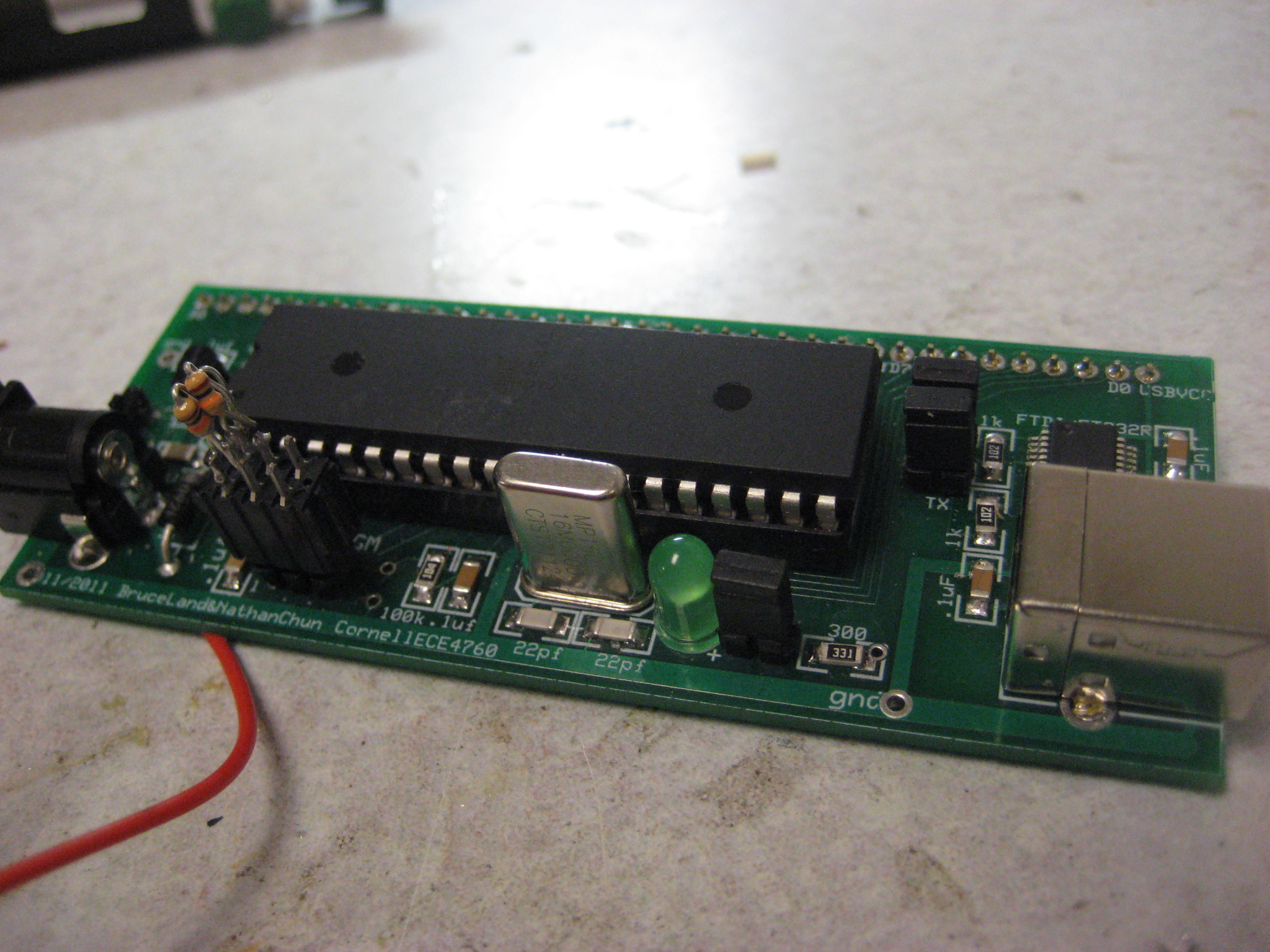
We used a ATmega644 board mounted on a custom-made circuit board designed by Bruce Land. The circuit board provides some key functionality to the project. For the end result, we have access to pins for SPI communication, which is important for the functioning of our project. There's a voltage regulator to switch a 9V supply down to 5V for MCU operation, which allows us to use either power supply from the lab or a 9V battery. There's also the serial communications port which we used extensively for debugging purposes. The final implementation does not need the serial comm port to function properly, though.
By the end of the project, hardware issues came up with the programmer, which uses pins B5, B6, and B7. After blowing one Mega644, we had taken precautions to program only when peripherals were removed and run the pogram without the AVR programmer attached. Nevertheless, we discovered an issue related to the programmer pins with the help of David Ackerman and Jon Amazon. We ended up having to solder a quick header to pull pins up to 5V Vcc. These are simply 10k resistors that tie MOSI, SCLK, and MISO to Vcc.
Voltage Regulator
Our project revolves around the implementation of different peripherals and being able to communicate with them. From the very beginning of our project, the need for a voltage regulator was obvious. The ADXL345 accelerometers and the SD and microSD cards are rated to operate with 2.7-3.6 V supply, while the Mega644 and the LCD's use 5V supply. For this, we used the LP2951 voltage regulators found in lab.
We found Texas Instruments' datasheet related to the LP2951 to be extremely helpful and clear about the design and application of the regulator. From this datasheet, we were able to program the regulator to output 3.3 V with constant 5V supply. This was a simple circuit, with a resistive divider from the output voltage to the LP2951's feedback port. This sets the input to the regulator's error amplifier equal, which drives it according to the equation (from TI)
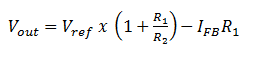
where Ifb was rated as typically being 20nA.
For 3.3 V, we set R2 to 10k and R1 to a nominal 16.7 k (created using a 5.2k, 1k, and 10k in series).
We included input and output capacitors early on to help with loop stability. In the final setup, the power supplied by the Mega644 was not AC, so we didn't need to use the 1uF input capacitor. Additionally, the load current out of the LP2951 is far below the worst case condition of 100 mA, so the 2.2uF output capacitor is also overkill. However, at the time we built the regulator circuit, we were still adding peripherals and wanted to be safe with drawing too much current.
After discussion with other project groups, we found that the schematic suggested by Texas Instrument was very robust and eschewed regulator problems that previous projects had encountered. We would recommend that any group shifting voltage level read the TI datasheet. The output voltage can be programmed at any level between the internal 1.235V and 30V, but other circuits might require more than just the resistive divider and capacitors.
ADXL345
ADXL345
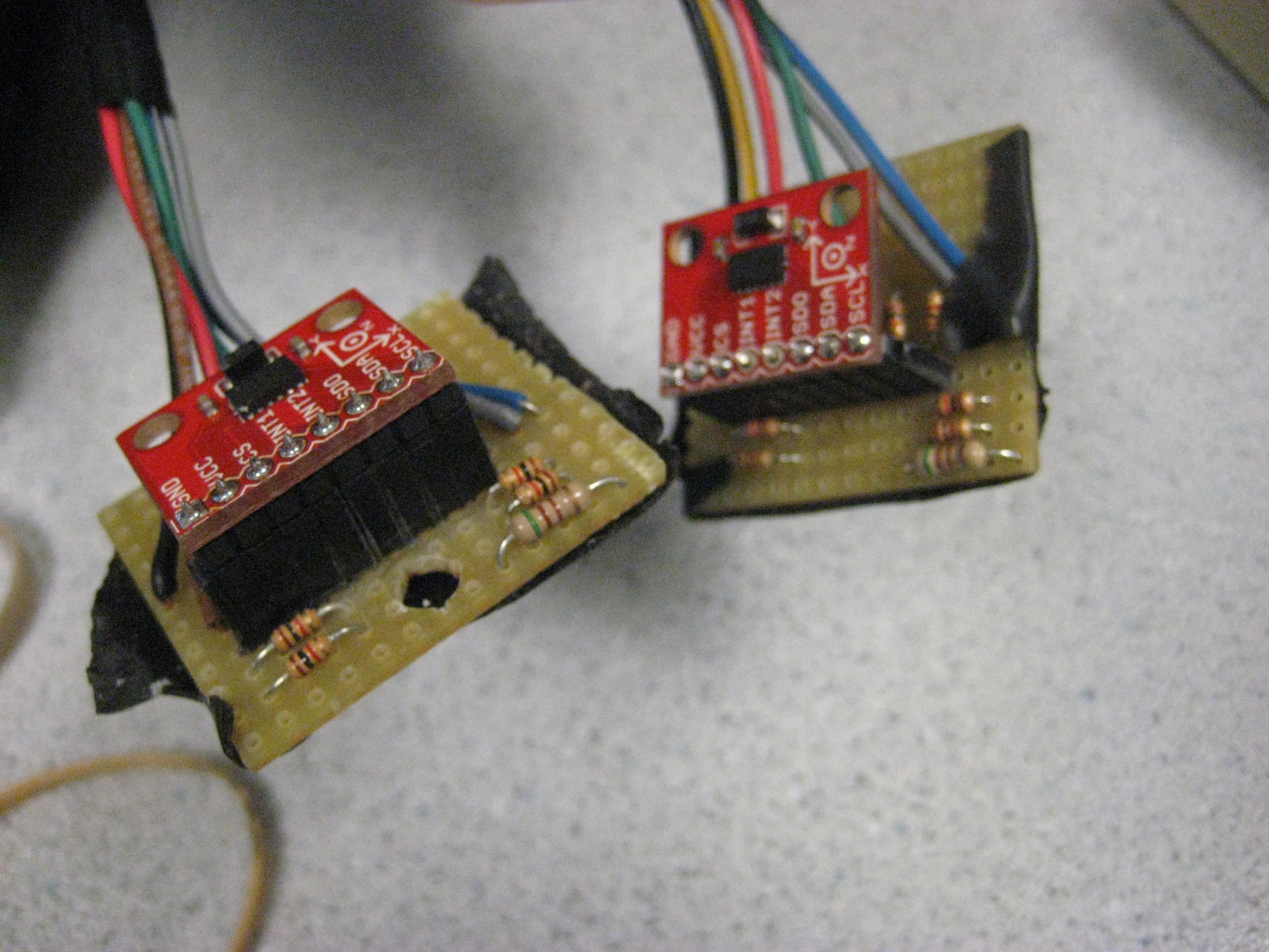
Our project revolves around the use of the ADXL345 triple axis accelerometer mounted on a breakout board. The breakout board has the pins neatly arranged on one side. From top to bottom, the pins are (as seen above), GND, VCC, CS, INT1, INT2, SDO, SDA, SCL. We didn't use the INT1 or INT2 pins in our project, so they remain unsoldered to headers. Because the accelerometers were borrowed, we used a small 2" solder board to build a dock for the accelerometers. The accelerometers can easily be interchanged then as the chips work.
The accelerometers are three axis accelerometers, with a range of +/- 16g at 3.9mg/LSB max resolution. Earlier on, we had been expecting to use at least two of the axes. As of our demo set up, we actually only use 1 accelerometer, so this code could be revised and reworked for 1-axis accelerometers.
MicroSD Card Adaptor
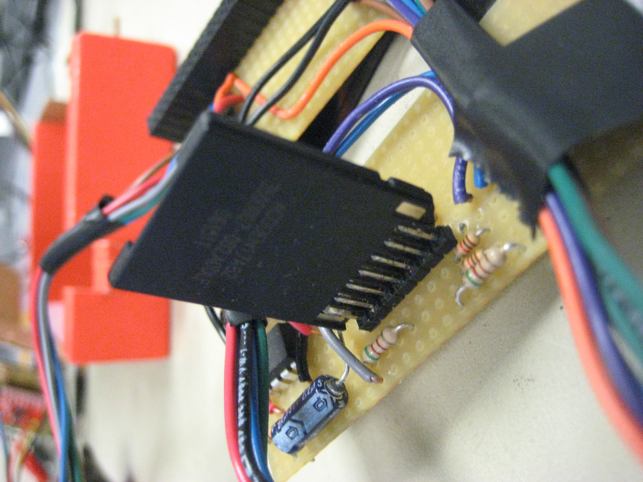
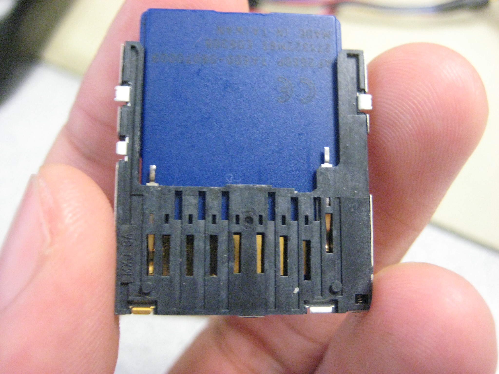
SD Card Reader
To log data, we decided to use an SD card to log accelerometer data whenever polling and calculations were finished. We chose this option for a couple reasons:
- Due to the plethora of applications SD and microSD cards have, any user would reasonably have a card around that can be used for this project.
- The price of SD sockets and microSD adaptors is much cheaper than a receiver/transmitter module.
The card sockets are just metal connectors from the solder board to the card's pins, and can easily be implemented with headers.
For the card themselves, we used a standard SanDisk 2GB SD card and (later on) a 4GB microSD card, which can be easily found and purchased commercially. Some projects used the SD cards with 5 V power, but we use 3.3V, as this is a safe operating range according to SanDisk.
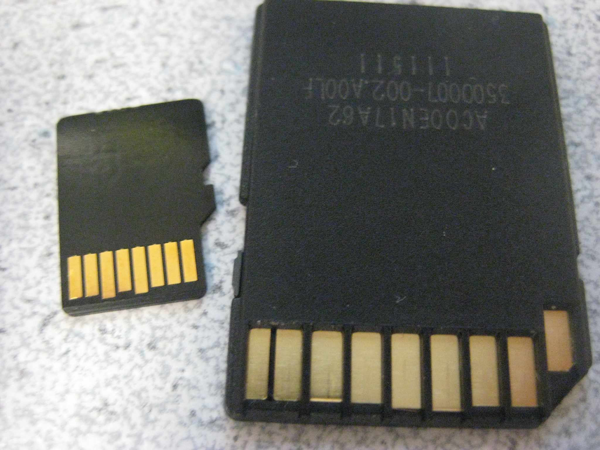
SD Card Pinout
For the purpose of our project, we needed to know the SPI pins that were available. both the microSD and SD cards have the same configuration as seen above, and as such, are interchangeable given the proper sockets.
From left to right, the 9 pins are:
N.C.; MISO; Ground; SCLK; VCC; Ground; MOSI; CS; N.C.
Broken SD Reader
Probably the only consideration that needs to made for the SD card reader is the structural integrity of the socket. Earlier on in the project, we had sampled SD card sockets from Molex which were simply metal cages with header pins. Because the location of the pins, the card was balanced precariously over header pins while being soldered to the board. There was no real support behind or underneath the card, which eventually led to the header pins ripping out once.
The microSD socket we used in the end is not much better. The socket is just a microSD to SD adaptor that has the pins soldered to header pins. There's no structural support, and one concern is that this is the least robust part of our hardware.
Voltage Level Considerations
For the two accelerometrs and the SD card socket, the voltage rating is set to 3.3V. We used the LP2951 regulator to supply a constant VCC of 3.3V to these peripherals, but some other circuitry needed to be implemented to shift from 5V to 3.3V on the master to slave SPI lines - specifically MOSI, SCLK, and the different CS liens. We tried a few hardware setups (that are briefly mentioned in Appendix A), but ultimately we use resistive voltage dividers to shift from 5 to 3.3V.
For the MISO line, the opposite issue is actually non essential. Initially, we believed that 3.3V would be just outside the digital "1" of the Mega644 and a switch was necessary to pull the voltage up. In actuality, 3.3 V is enough to register as a 1, and so we can tie the MISO pin (B.6) on the MCU directly to the different peripherals' output.
LCD Screen
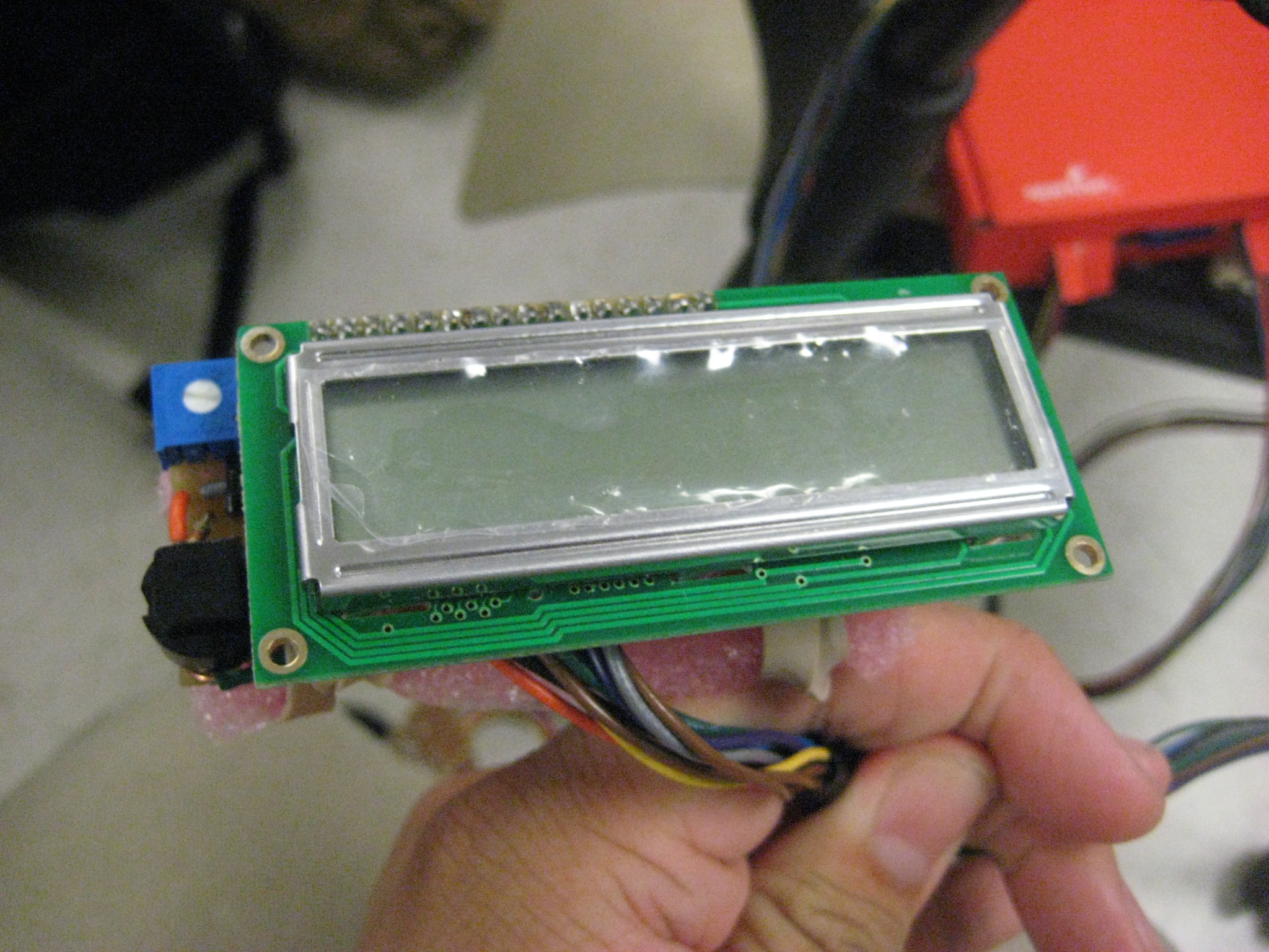
LCD
For this project, we used a simpler LCD that we used throughout class. As with other labs, this LCD was routed to Port C. For ease of functionality, we have the LCD attached to a longer set of wires, so that the user doesn't need to bend down to the MCU to read out data. For a bit more flexibility, we have the potentiometer that controls the contrast on the board near the LCD. This gives more control to the user, and also means one less wire being routed all the way from the MCU.
Button setup
Later on as we progressed in the project, we wanted to enable the user some functionality and control over starting and ending data logs. To do this, we added a button close to the LCD screen that the user could easily access. The button itself is a simplistic push button, similar to what the STK500 uses and what we have used in lab. The only thing to note is that when we soldered it, we used a pull down resistor to tie an open circuit to a digital value. When the button is pushed, the attached pin will be pulled to Vcc, or 5V. Contrary to buttons on the buttons on the STK500 used in earlier labs, this button is active high. There's no strong reasoning behind this, and as with any buttons, the designer can use active high or low. The program would just need to change accordingly to reflect an active high or low button, which can be done simply in a define statement.
Overall setup
Our final project is meant to be worn and should be usable during operation.
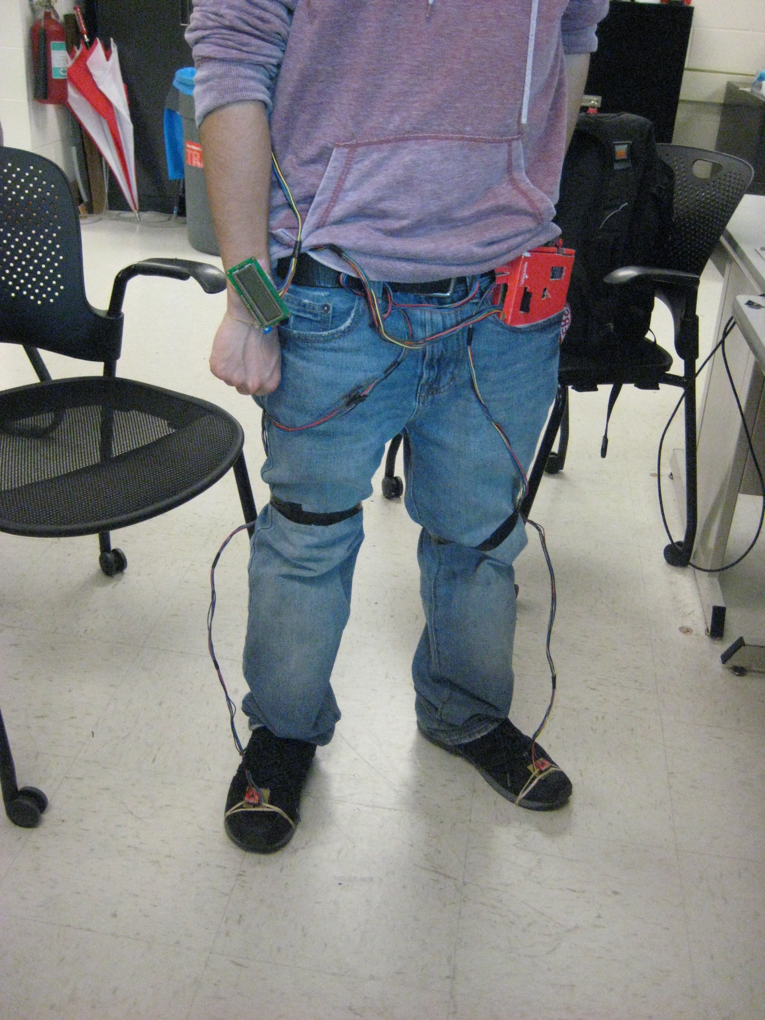
Above, Tim is demonstrating how our project can be harnessed and worn. The LCD and button is attached to the right arm for easy reading of data while traversing. The majority of the circuitry (battery, Mega644 board, SD card, voltage regulator) is small enough to fit in a small box. We conveniently had a Sparkfun box on hand, and we used this to hold this circuitry. It's a bit cumbersome, but it does fit into pants pockets well enough to prevent falling out during operation. Some slots were cut into the box to allow for the SD card to be easily accessed, the programmer resistive header to fit, and for the user to turn on power.
The accelerometers are wired down the legs, and each accelerometer is meant to rest on top of a shoe, with the z axis (the axis normal to the breakout board) oriented up. We meant to get boxes for the accelerometers to protect from rain or to make it easier to strap onto shoes, but we were unable to find good sized boxes, so we just used rubber bands to hold the accelerometers in place. At one point, we used a tin box lined with electrical tape to prevent pins from shorting out, but we abandoned this idea. We weren't sure of the reasoning, as we had enough electrical tape, but we narrowed down the reason to some interaction with the box.
Software Design
SPI | Accelerometer | SD Card - SPI | SD Card - FATFS | Data Acquasition and Calculations | MATLAB Script | Button State | Data State Machine | TRT and Timing | LCDThe majority of our code was written in C using the Atmel MEGA644 with AVR Studio, as has been done throughout our class instruction. Additional code was written in a simpler MATLAB script to load data from the SD card and plot it . This section seeks to breakdown major components of our program and discuss the details and purpose of code. Whenever code is borrowed, we will explicitly reference the source (as well as provide links in the appendices), and if possible, provide any commentary and insight that can prove useful for future projects.
Our source code can be found and downloaded in Appendix C
SPI
A quick note before we begin discussion of our code: two of our peripherals use the SPI communication protocol extensively. The 4760 course website has a helpful introduction to SPI, especially with regards to its implementation in the MCU. For better understanding of what we discuss below, we suggest reading the information written by Professor Bruce Land.
To keep different slaves unique, we will need to use different pins to act as different chip selects. For the sake of ease, what proved easiest is to use B4, B3, and B2 in that order of additional peripherals. In the event that more slaves are needed, other pins can be programmed too, but one would need to refer to the Mega644 datasheet before selecting a pin.
To ease the ability for the MCU to select different pins, we use a couple macros adapted from SparkFun's arduino tutorial for ADXL. Our code only uses two of the macros, but we provide four of them: READ, SET, CLR, and FLIP, each with an input for port and an input for pin number. As the names imply, the macros read a pin, set a pin, clear a pin, and flip a pin. Using these macros is helpful, as it makes it clear to see and understand which particular pin is being altered.
One key detail for future projects - make a note of the default SPI pins that the MCU uses: B4 through B7. The variable indicating data direction DDRB must be set to include these four default pins - even when debugging another slave, B4 must be set as an output and pulled high for SPI communications.
Accelerometer
As the ADXL345 accelerometer was a major component of our project, a central part of writing and testing our program was to set up the chip and enable acquisition of data. Upon successful initialization, the ADXL345 will properly react to environmental conditions (eg - rotating the accelerometer to respond to gravity) and the data can be read off the chip. Communicating with the chip itself is not a difficult task. The MCU must preface any action, read or write, with the register address that is being accessed.
When initializing the accelerometer, the only register that must be written to is 0x2D, or POWER_CTL. If the measure bit is not set, the accelerometer will stay in standby mode and not output any data. Other than this register, no other registers are a necessity, as there are default settings for the accelerometer operation. For our project, the default settings were mostly sufficient. The only setting we made was to set the range to 8g at full scale resolution, giving us 3.9mg/LSB sensitivity.
Another setting we played around with was the data rate. For a lot of the time, we used a 100Hz output rate. Our goal was to try to reduce error by increasing the number of samples averaged. Doing so with a 100Hz rate would prove inhibitive to our processing speed, as we would need to wait 10ms to take new data. Instead, we upped the data rate to 800Hz so we could sample quicker. Because FIFO is not enabled by default, we end up dropping samples when we are not polling the accelerometer. To fix this, we just woke up our task stepData more often.
Reading data from the accelerometer was relatively simple. After initializing the chip, the user just needs to write the register address for the data and read out the data from the SPI shift register. An important note is that because the data is more than 8 bits, we need to concatenate the values, Thankfully, the address that is used as input will automatically increment to the next register after a successful read, and the data registers are adjacent. This means that we don't need to release the chip select before reading the next register. The accelerometer updates data registers when the chip is not selected, so keeping the CS bit low means the data won't refresh. This is quite significant - there is a substantial difference from reading a valid 0x00FF or 0x0100 to reading two data points and concatenating to "read" 0x01FF.
SD Card - SPI
The other peripheral that used the SPI protocol is the SD card reader. Here, the SPI is a low level I/O protocol that is used as communication between the MCU and the card reader. This implementation helps with the
The SPI capability for this is not significantly different from what's written above for the accelerometer, but there are a few distinct differences for software. One of the most obvious comes from the chip select. As this is a distinct slave, another pin is needed to act as the active low CS bit. For the SD card, we decided to use B3. There wasn't a particular reason to use this pin instead of B4, but as the SD card was added second to our program, it was moved down one. Another differences revolves around how data is read. Unlike the accelerometer, which writes the register address before taking action, the SD card appears to only have one SPI register. This observation is derived from the lack of any addresses in the low level rcvr() and xmit() functions found in mmc.c . Instead, the SD card appears to accept commands and transmit responses via SPI.
Other than these rather simple interfacing differences, the SD card still follows SPI protocol - the code will be remarkably similar to the ADXL. The differences do mean that there need to be unique write and read functions for the two peripheral.
The source code that enables the SD SPI usage is called mmc.c in our code. This is code written by ChaN for AVR interfacing with the FATFS module described below. In order for proper use, customization of this code is needed. We made the following modifications to the default 2010 version of mmc.c :
- Commented out significant parts of power_on() - the code for power_on initializes SPI communications, but our main code already calls this function from another source file.
- Redefined select and deselect based on our use of B3 instead of B4, and also changed around the implementation so that the act of selecting and deselecting the SD card made a bit more sense in terms of atomic actions. (The original code has select() deselect the SD card if it cannot establish a connection.)
- Change the power_status to return 1 by default - originally there's functionality associated with PORTE, which is not present on the Mega644.
- Comment out power_off() - if the disk cannot initialize, we do not want to disable SPI functions (we can still utilize the accelerometers), but rather just ignore any SD related code.
SD Card - FATFS
Using SPI allows I/O communication to the chip, but this is entirely low level. We want to use a mid level file architecture to ensure that data can be logged into files that are readable on other computers. After looking at some prior projects and discussion with lab TA's, we discovered FATFS, written by ChaN and discussed thoroughly by Frank Zhao. Regarding the software implementation, we really have very little to add.
FATFS is a module that was developed for embedded systems and microcontrollers to interface with file architecture peripherals like an SD card. Open source code is provided for various tasks - creating directories, opening files, making files, reading files, writing characters, etc.
A very useful functionality of this module is the inclusion of error codes. When debugging code or testing out hardware, these error codes (returned after every defined method) correspond to an error defined in ff.h and give great insight to whether issues were hardware oriented or software oriented.
For our program, we initialize the SD card at the very beginning of the code. Upon a button press, we attempt to open a file using f_open(). We set the flags to FA_WRITE | FA_CREATE_NEW so the system attempts to create a new file we can write to. If this is successful, we continue to data logging. If it isn't, it's possible the problem is that file already exists (the error code would correspond to FR_EXIST), in which case we increment a counter until we can open the associated file. If the file cannot be opened for whatever reason, we clear a flag that prevents our code from attempting the tasks of writing, synchronizing, and closing the file.
To write a line of data, we write our data to a character array, and then write this array to the file using f_write. However, the file is not properly synched with the disk yet. This is ok in some cases, but because our usage is as a data logger, we want to write this to the disk so that in the event of a system crash we still have some useful data. So everytime we write to file, we need to synch this object. f_synch is incredibly useful, as it can write data from file to the disk without the need to close and reopen the file.
When the user indicates the end of a file log, we simply use f_close to shut the file and end this data session.
Our project is geared toward logging data, but some projects might be aiming to read data from a disk instead. One useful project in particular would be the car mp3 player created by Chris Dolen and Matt Watkins in SP'11.
Data Acquisition and Calculations
The majority of the math behind the calculations has already been discussed in the section for background math. The only software details concerning our calculations we haven't discussed pertain to how to take step data and go to distance.
As mentioned then, our idea of distance is an integration of the speed, which is the pace multiplied by the step length. To find the pace, we use a method similar to determining rpm from Lab 4 of semester SP'12 . We can calculate the period of a step using simple timer based counters, and from this we can reasonably derive the "frequency" of stepping. As people may have an even step or may be changing speeds, we need to use the running average of the pace to give a reasonable measure of the speed throughout the data. At the same time, we need to make sure we can zero out the frequency in the event that a user steps and doesn't take another step. To do this, we arbitrarily impose the constraint that a step must occur within 2 periods based on the average frequency. If not, we will zero out these values. There will be a bit of an overshoot since the
Step length is rather arbitrary and will differ between people. Our numbers are currently calibrated around Tim, but in general, we can say that there are different step lengths based on pace. Similar to how we use a threshold to determine which delay to use when calculating the jerk, we use a similarly arbitrary threshold to differentiate between regions of walking - slow, normal, faster, and running. Each of these have their own step length that is empirically tweaked around.
Now that we have the pace and the step length, we have a function that calculates the differential distance as a differential slice of time multiplied by the multiplication of step length and step speed. And of course, we sum it up over time to give a measure for distance traveled.
MATLAB script
The MATLAB script is a separate .m file that should be included on the SD card. The purpose of this script is to generate some plots from the logged data that could be significant to the user (whatever they seek to know).
The script is really open to whatever the user wants to do with the data found on the SD screen. At the time of this writing, the script is really meant for debugging, and will graph step data over time, as well as acceleration data to determine if the step count was reasonably accurate. There are also graphs for the jerk and the average, so we can differentiate datasets between the speeds and observe when faster steps are occurring.
Button State
To give the user greater flexibility with the system, we implemented an active high button that would allow the user to start and end trial runs without necessitating a power cycle. With regards to the data logging, this allowed the user to safely open and close files. Because this end-point is user defined, it only made sense to include this with some form of button logic.
For the button logic itself, we use a basic button state machine. There are two main steady states: PUSH, and NOPUSH, clearly representing when a button is pushed and when it is not pushed. As might be expected, if a user were to never touch the button, it should stay in NOPUSH, and if the user is always holding it down, it should stay in PUSH. But a physical button will experience issues with debouncing, switching between analog high and low signals.
This means that we need to properly debounce the switch and determine when the button has been pressed (or not pressed) for a sufficient amount of time so as to enter steady state. We introduce two more transition states: MAYBE and MAYBENO, representing "maybe pushed" and "maybe not pushed." The transition states serve as the intermediate stage between steady states, so that on an edge, the transition can begin, but the value must be held for a proper duration in order to properly be debounced.
There were two software implementations possible for the button - an external interrupt based on a falling edge, or a periodic polling. Because of the issue with debouncing, the periodic polling seemed a more appropriate selection despite the sacrifice of some computer utilization. Instead of implementing this as another task, this became part of the Timer 0 ISR. This was a natural choice, as we already had the ISR set up for 1ms iterations. Adding a soft counter to mark off 30 ms (what our instruction in the course noted as being "long enough" for a debounce) was simple, enabling us to call a helper method buttonstate() every 30 ms.
While the code called in the ISR is simple, the implementation and effect this has on the rest of the code is more significant. Polling the button state from the ISR only tells us what state the button is in. There's no indication if a pushed button has been processed, though, so we must introduce a flag that lets the system know to process a button push. This is a rather simple flag - we set the flag in the ISR when the button is set to PUSH, and then we clear the flag after we process the button push. To process the button push, the flag must be set, and since that only happens on the transition to the PUSH state, each push will only be processed once.
Data State Machine
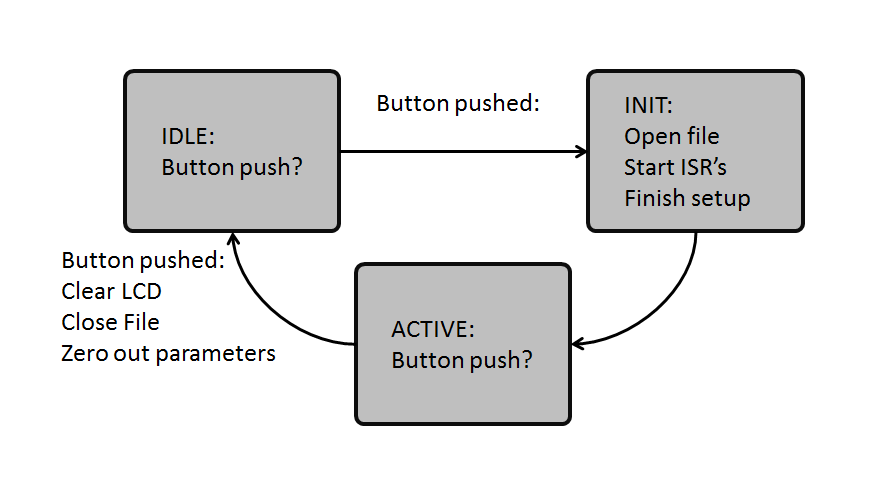
The reason we introduced the button was to add some functionality and give our system different states. That ensured that the user could control when data was being acquired versus idle. The state machine in this case was relatively simple - the system is either acquiring data or is idle. We used a variable named runstate and defined three states: IDLE, INIT, and ACTIVE (0, 1, and 2 respectively).
Program State Machine
The IDLE state, as can be reasonably deduced, represents the point when nothing should be happening. No accelerometer data, no data logging, no timer increments. The ACTIVE state is the other extreme, where we're reading data from the accelerometer, performing calculations, logging data, everything. In between, we have an INIT state that has only one task - to initialize or reinitialize different accelerometer, SD, and program settings. This includes the time of duration, the distance traveled, and the file that is being written to, among others.
The INIT state will automatically transition to the ACTIVE state, which is the state where data acquisition, calculations, and data logging will occur. We wanted the transition between states to occur in the stepData task, so that whenever the button was pushed and a program transition triggered, we could make sure that at least one more final dataset is logged properly.
TRT and Timing
The Tiny Real Time (TRT) multitasking kernel developed by Dan Henriksson and Anton Cervin is used as the backbone system. It is an earliest deadline first scheduler and allows for multiple tasks to run concurrently. Our system only uses two primary tasks: a task that performs all the sampling, calculations, and logging, and a task that prints relevant data to the LCD screen. The TRT system allows the user to multitask the slow LCD function by interleaving actions from another task in order to sample data from the accelerometer quickly enough.
LCD
The LCD code is relatively simple and based on test codes from previous labs of SP'12 . The LCD functions in of itself are not complicated, but integrating the code with the other tasks proved to be an interesting challenge. The LCD buffer updates the screen serially, one character per millisecond. With a 16x2 array, this update can be extremely slow compared to other running tasks. Therefore, special care needs to be taken with respect to the timing of how often the LCD function executes.
Using the TRT kernel, it is possible to concurrently execute the step data function while interleaving LCD functions in between. This allows for the step data function to execute without needing to wait the lengthy period of time for the LCD to update. Especially if more processor heavy functions are included in future updates, running the LCD concurrently will allow a significant speedup in sampling rate.
Semaphores need to be included in LCD functions related to the button push because the button push forces an interrupt to be triggered context switching the current task. The SEM_LCD_SHARED semaphore protects the variables when they need to be copied to the LCD. The copy to LCD commands that are relevant after a button press are therefore encased in semaphores to wait for the LCD to finish updating and vice versa. If the LCD buffer has not completely cleared, then this will cause a error that results in gibberish characters being displayed on screen. At best this can be cleared by pressing the button again to clear the screen but at worst, a hard reset may be necessary to solve the problem. This entire issue can be avoided by using semaphores.
Results
Speed of Execution | Accuracy | Safety | Interference with Other Designs | UsabilityThe results of the design are reasonable given the hardware limitations and prototyping status of the project. The user is able to wear the four main pieces of the project (accelerometer on each foot, MCU at hip, and LCD on a wrist), without much difficulty although keeping them on the body during extensive running may be difficult. As described in the logical flow, operation by the user is fairly linear and straight forward.
Speed of Execution
The project currently does not experience any sort of lag and should not interfere with the user experience. The LCD screen refreshes roughly once every quarter second so the user should not notice any delay between a proper step and the update on the LCD. Additionally, the program checks the state of the push button every 60ms so the response from the push button should be instantaneous.
The inclusion of the TRT kernel allows for the program to execute LCD update commands concurrently with the data sampling from the accelerometers. This ensures that the data sampling functions do not need to wait for the slow LCD to finish updating before beginning another iteration of data acquisition. However, a problem arises if the scheduler context switches away from the LCD update before the buffer has completely written to screen. This results in the LCD screen rendering unknown characters that cannot be cleared without soft resetting the program with a button press and on rare occasions a hard power cycle. This issue is resolved by placing semaphores around the update LCD function at the cost of slowing down the number of samples that can be taken per second.
The setup, calibration, and shutdown times are negligible during real time testing of the device. The initialization of SPI bus and each of its peripherals including the calibration of the accelerometers does not take more than a few seconds at most. Closing the file to the SD card and beginning the subsequent IDLE state is barely noticeable by the user. Therefore, in practical operation by the user, very little time is spent in non-data logging mode.
The step data function operates at approximately 50ms per iteration, therefore the The amount of data polled by the system is highly dependant on the release time given by the TRT kernel. The scheduler currently releases the data logging function every 20ms and can be increased depending on the amount of necessary load on the system. Based on empirical data, subsequent steps do not occur less than 200ms apart even while running. Data is shown to be accurate even with a TRT release time of 100ms. Although higher speeds will result in more data points logged into the MATLAB program for finer analysis, it does not significantly affect the real time calculations and their accuracy.
The LCD screen has a much stricter bound on its TRT release and deadlines because of the slow nature of how it updates. At refresh frequencies slower than 750ms, the user begins to notice that while the step counter is accurate, they do not track real time with the user steps because the LCD has not completely updated. Especially because the screen is guaranteed to update every second from time, slower rates are unacceptable and result in the clock skipping seconds. Conversely, the LCD screen must not have a release time much faster than 250ms because then it begins to interfere with the data logging processes since semaphores must be held on certain variables and the button so that the system does not fail. Luckily, the average human perception cannot track changes faster than 200ms so the update should be seamless to the user.
Accuracy
Initially, we implemented a dead reckoning algorithm to calculate the forward velocity and distance traveled by the user. However, this was unsuccessful and the details will be outlined in the appendices. In the final setup of the project, we use a much simpler method of determining user speed based on the frequency of the steps taken and the distance traveled based on an approximation of the distance traveled per step with current speed as a variable.
Beginning with the step count, four different speeds were tested: slow walk, medium walk, fast walk, and run. In each of these trials, an average user tested the device under normal operating conditions and each set of 15m trials produced step counts with errors at most 1 step away from the actual count. Additionally, trials were conducted in Duffield Hall of Cornell University with real world conditions including stopping, turning, changing speeds, and stairs, all of which produced near perfect results over 500 steps.
Although we did not have a formal method of comparing the speed calculations of the project, the distance calculations are a direct product of the speed calculations and both metrics can be compared to actual distance traveled. As with any form of integration, the accuracy is never perfect, although this particular algorithm is much better than dead reckoning. Given that static thresholds are used to determine the distance per step based on step frequencies, there will always be some measure of error. Additionally, this must be calibrated to the user based upon a lookup table or mathematical function which would be difficult to implement at this time.
That being said, our current calibration is accurate within a few meters and improves as more distance is walked. With 15 meter trials, accuracies ranged from 0.5 meter error for slow walks, to 2.5 meter errors for faster walks and runs. Over an actual distance of 75 meters, we were able to obtain a calculation of 77 meters walked. Therefore, while the distance calculated is not perfect, they are within a ballpark range of the actual values.
Safety
There are no components in our project that pose even mild risk to the user or the surrounding environment. The current drawn through the components are negligible and the main MCU and voltage regulator are encased in a box away from direct user contact. All exposed leads are either covered with electrical tape or ESD foam to prevent skin contact.
With regard to the design process, we used the utmost care to follow all safety procedures. Care was taken when soldering with respect to both self and other lab users. Additionally, special mechanical concerns were considered when cutting material using the dremel tool.
The one concern that can be made is with regard to the long wires attaching the accelerometers to the MCU box. They must be either carefully taped to the users legs or placed inside his or her pant sleeves. Otherwise the long wires may cause discomfort to the user while operating or in extreme cases, cause the user to trip and fall. Therefore, it was determined that in the prototyping stage of the project, the length of wires would be designed to fit the primary testers height to reduce wire slack.
Interference with Other Designs
Since all communications are transmitted either directly (through the SD card) or over a wired SPI bus, there is no possible interference with other designs.
Usability
The design is straightforward and simple to use for all users who are able to walk without external assistance. It was tested that even users with slight walking disabilities are able to effectively use the device. The only concern is that the prototype device has wires that are cut to length to our primary tester who is 5ft 4inches. As such, taller individuals may find it difficult to attach both accelerometers to their legs while pocketing the MCU box. Additionally, current distance calculations are based upon a specific stride length and may need to be recalibrated for other users of different height. Future considerations may include a data lookup table or mathematical function which will map user height to stride length to be accurately used by all people.
Conclusions
Future Considerations | Legal Considerations | Ethical ConsiderationsAfter calibration of the exercise measurement system, we were quite satisfied with the results of our system. Not only were the number of steps near perfect for hundreds of steps, but this was true given different speeds of walking and even when walking in day-to-day activities. Although the distance calculations were not perfect, given the hardware limitations of commercial accelerometers, they are fairly accurate over longer periods of time.
One of our benchmarks was to have the data recorded on an SD card and plotted onto a graphical system to analyse the data at a later time. The MATLAB plots far exceeded our expectations and as seen in the appendices, we were able to capture numerous plots with different data metrics to help us in further calibrations.
Future Considerations
With the groundwork for much of the basic hardware completed, there are numerous directions that the project could be extended upon. One possibility that was considered is the inclusion of a GPS module to calibrate and refine distance calculations outdoors. By combining GPS which is accurate up to approximately 20 meters and our system, we would be able to much more accurately calculate position and even overlay the data onto a coordinate system. It would have been very interesting to combine our project with Edgar and Brian's outdoor GPS logging system *[link]* to determine the improvements in distance calculations and also map out a user's walking history.
A second possibility is to improve the real time display system by taking what is currently displayed on MATLAB and plotting that data onto a higher resolution LCD. The MCU is already able to do all of the floating point calculations necessary to plot the data so the graph would only need to be rendered with the new LCD.
Finally, the prototype system currently uses a fixed length wire to connect various peripherals to the MCU box. By using wireless modules, the application could be extended to any users regardless of height. Additionally, since real time data could be sent to the MATLAB program, more efficient calibration data could be obtained.
Legal Considerations
The majority of any legal consideration we must discuss concerns intellectual property. Otherwise, we do not use any hardware component that must be regulated by any federal standards.
There is a fair amount of code that we were able to use from the public domain, whether via class or online sources.
Code from the ECE 4760 class include:
- lcd libraries - lcd_lib.c and lcd_lib.h
- TRT related code - C files noted by the "trt" prefix: trtUart.c , trtUart.h , trtSettings.h , trtkernel644.c
- general UART communication code - uart.c and uart.h
Code related to the FATFS module include:
- low level I/O defines - diskio.h
- the FATFS module - ffconf.h , ff.c and ff.h
- integer definitions - integer.h
- the SD control - mmc.c
We also adapted some definitions and methods from SparkFun's ADXL Arduino in spi_init.c, spi_init.h, and adxl345.h.
All these codes are found from online sources and are publicly noted to be public domain.
In the introduction section, we discussed the innovation that Neil Zhao's article in Analog Dialogue brought to our design. We also mentioned how the design and method discussed in the paper was very similar to what we sought to achieve - we want to be explicitly clear that while we did implement the idea of using pace to determine distance traveled, we were NOT reverse engineering this particular pedometer. We were using their idea with an already existing and developed hardware design and step detection method.
There were no non-disclosure agreements to sign to obtain the ADXL345 accelerometers and the Molex card readers. Technically, we didn't have to sample the ADXL345's, as we borrowed them from Professor Manohar, but we checked that there would be no agreements if we wanted to sample them.
Regarding the direction of this project, it is unlikely that we will pursue patents or publications. Both require novel developments of technology, and we're not sure how novel our project is considered, given the plethora of pedometer and accelerometer related literature. Further, we utilize SD cards, which are patented and can lead to royalties if we were to go forward with publication or patents. We personally feel that this project provides more of a research background and foundation from which other projects could start. However, we will still discuss with Bruce about the likelihood/possibility of anything. Bruce has been nothing but encouraging through this semester and has much more experience, so if he has strong feelings regarding opportunities, we will take it into great consideration.
Ethical Considerations
In compliance with the IEEE Code of Ethics , we sought to conduct ourselves in an ethical and professional manner befitting of engineering and academia.
As this is more or less a prototype, the design could be further refined in terms of hardware and circuitry. Nonetheless, in compliance with point 1's desire for full disclosure, we want to acknowledge the following factors that a user of this system would need to be aware of:
- The accelerometer dock and LCD strap are open air in the current setup. As such, water is a serious factor to consider - especially for the accelerometers, as soaked shoes will be harder to dry than the arm. This is especially pertinent as the conceived typical application is someone logging their travel in some duration of time and this can easily apply outdoors.
- The current harness for the accelerometers consist of rubber bands. This is not meant to be a permanent solution at all - this is meant primarily for testing purposes and was not resolved due to time constraints. However, rubber bands snapped quite a few times, and the accelerometers could whip off the foot easily. To the best of our ability, we tried to test our setup when few people were around to prevent
- The current harness for the wires is rather primitive - it consists of looping wire through belt buckles and/or taping to pant legs with electrical tape. In the case that the electrical tape fails or the MCU box falls out, the wires and box immediately become a potential tripping hazard in front of the torso and legs, especially at higher speeds. Any future iteration of this project will need to resolve this issue if ever a commercial product is sought, whether via the implementation of wireless communication or a better method of adhering wire to the body without obstructing walking.
Concerning other matters listed in the code of ethics, we feel that we have satisfied safety conditions in lab use and device testing. As mentioned above, we ensured safe usage of the solder iron and Dremel tool whenever we needed to use them. We tried to isolate electrical components using electrical tape for the peripherals when possible, and in addition, we added a foam piece beneath the LCD to prevent any connections from pricking or puncturing the arm.
Regarding bias, we sought to make no discrimination toward anyone. The acknowledgement must be made that the hardware as it exists - specifically wire lengths- has been calibrated and designed around Tim's frame. For a person of considerably different stature, wires of different length would need to be used. The system itself would not function any differently, but either devices of different sizes would need to be built, or we would need to implement short range wireless to communicate between base and peripherals.
One concern had been a person with a form of walking impairment would not be able to utilize our device. People in wheelchairs would not be able to use our device, but they would also not represent the target audience of such a device. A more relevant group would be people with limps, walking with crutches, or in casts. Conveniently, Aaron was in an ankle brace for the week before presentation, so he could confirm that the device could record steps reasonably accurately. There would be a need to recalibrate the length of a stride to get more accurate distance calculations, but this recalibration is more global due to the variation in stride lengths among the general populace and not discriminating against a group of potential users.
This is relatively minor, but in the interest of deterring any claims of bias, we want to disclose that the LCD strap has been designed to be worn on the right hand. This is purely coincidental and due to the location of the button in relation to the LCD screen. It is still fully functional and usable on the left hand, and the hardware can be altered to "operate better" on the left hand.
Regarding the pursuit of technological progress and understanding, our entire experience and project has been centered around improving technical competence. Our project inspiration comes from a desire to rework a previously failed project into a functional form with increased complexity. Even though we were driven to get the project working, any setbacks in hardware or software was isolated and analyzed to the best of our ability and solutions derived. Our report is written to provide and/or enhance understanding of different concepts, and we tried to write this in a manner that can be easily referenced for future projects - especially for SD card issues