Introduction
We were inspired to build an ultrasonic security system for our final project by our housing situation this summer. Security is an important part of home, especially if we are going to share a house with prior strangers without a lock on our room door. Yes, that is the situation we are walking into in order to drive down the cost of living in NYC. And we anticipate that many college students could face a similar problem. What is not to love about a device that looks like WALL-E and scans around for possible intruders? In case of intruders, it sends off a sound alarm and alerts the owner via email. It is also password protected and could be disabled via the correct password.
High Level Design
Rationale for project idea
We came up with the idea because it could help us and others protect property and privacy. Traditional household security systems often require installation and detect based on opening of doors and windows. In the cases where installation is not possible and/or the area of interest has no door, our ultrasonic security system will come in handy because it requires no installation, and detects intruders based on their physical presence.
Overview
The system uses ultrasonic sensor that has a transmitter part and a receiver part. The ultrasonic transmitter periodically emits ultrasonic signals into an open area in front of it. To cover a wide range, a rotating servomotor is used to allow the sensor (transmitter and receiver pair) to cover roughly 180 degrees. If the signal ever hits a physical object, it will be reflected back and, the receiver part of the sensor will then capture it with the object considered detected as its position (distance from the device and angle relative to the device) is now known. As the security system sends off a sound alarm, the object position is polled by our MATLAB script, which then plots it on a graph and log the record. The record log is also sent as an email to an address set by the owner in advance.
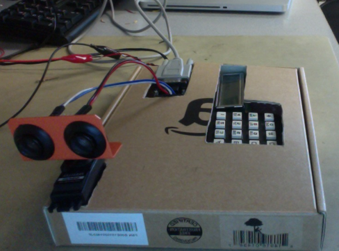
From the user's perspective, here is the flow of the system: LCD indicates user may press the button "A" to start. After user presses "A", the LCD further asks user to set up a password that could be used to disable the security system later, followed by the button "#". After the user finishes entering the password, the password is stored for the session, and the security system becomes active: motor starts rotating, sensor is scanning for potential intruders within a distance (15 cm for our demo, but could be anything realistically. It is only constrained by the sensor range, which is 5 meters theoretically), and in the case that an object is detected, the system beeps and triggers MATLAB to send an email containing the time of detection to the user. If the user wishes to disable the security system, he or she could type in the password used to set up the session. LCD will then indicate session is ending, and a new session is started in 2 seconds.
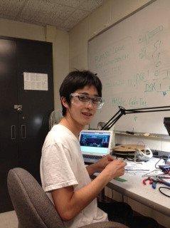
This is a photo of our completed security system:
Logical structure
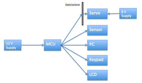
We will first talk about our hardware logical structure. The key hardware for this project are Atmega644 microcontroller, URM37v3.2 ultrasonic sensor, Parallax servo, LCD, and a keypad. The microcontroller sends the LCD various message depending on the system state. Also, a user is expected to enter a password each time he/she begins and terminates the system through the keypad. Finally, the microcontroller communicates with both the sensor and PC (MATLAB) via same rs232 serial port. Therefore, the sensor and MATLAB distinguishes the commands by using unique headers.
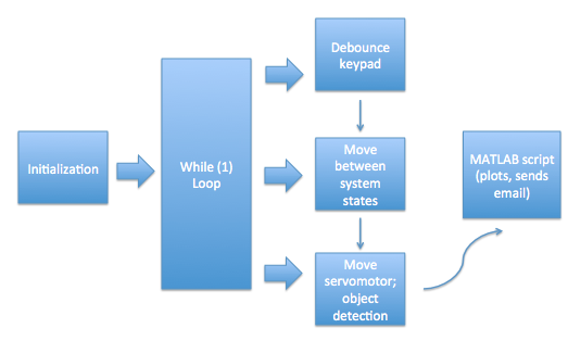
Now to the software logical structure. There are three functions that our C code runs periodically: debounce function that debounces keypad in order to read user input correctly, the system state function that moves through system stages (waiting to password to on, on to OFF, setting up passwords, etc.), and the active security function that rotates servomotor and sends signal off to detect potential objects. We will describe all three functions in more details under the Software Design section. These tasks go off at different times as they each have their own countdowns, decremented and reset accordingly when a timer interrupt is received. Once their times are up, the tasks are called by the while(1) loop in main. Debounce task sets a flag when user presses keys, this flag helps the second task to move system to the next state and operate accordingly. The second task also sets a flag when the system state is set to ON, and this flag is needed for the third task because we only rotate our motor and look out for objects/intruders when the security system is ON (owner has set up password and system is ready to go). When an object is detected, a trigger is sent to our MATLAB script which has been polling for an intruder trigger. Once the MATLAB script is triggered, it plots the object's position and sends user an email.
IEEE and FCC regulations
As far as we understand regarding the FCC standards, none applies to our design. This is primarily because our design is an ultrasonic transducer, and not an RF. Furthermore, we have closely familiarized ourselves with the IEEE code of ethics. In particular, we have accepted responsibility in making decisions with priority placed on safety, health, and welfare of the public during our final project. One safety consideration here may be that, as our security system goes off, alarm sound is blasted and LED is programmed to flash. We have carefully calculated and planned the magnitude of our alarm during the implementation of the final project, as abrupt siren of great amplitude may cause health hazard to those with heart diagnosis.
Hardware Design
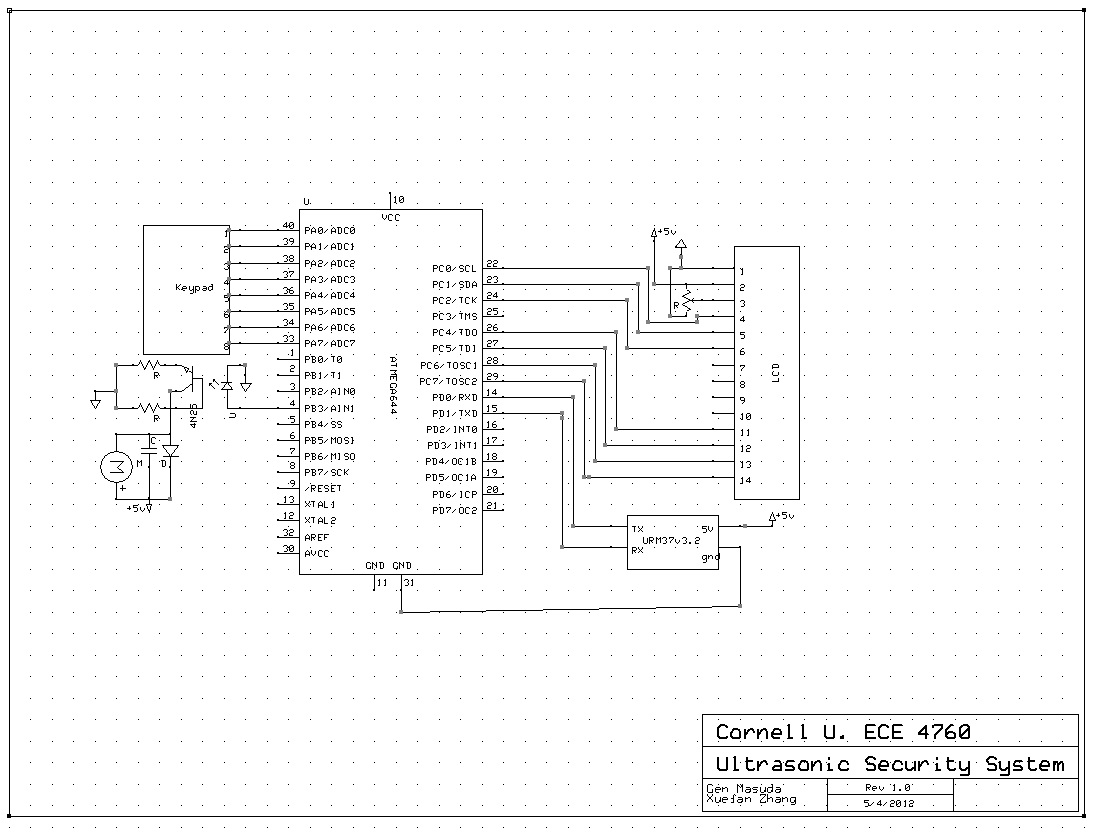
The Atmega644 microcontroller was used to interface with the URM37v3.2 ultrasonic sensor via rs232, Parallax standard servo motor via PWM, and to the MATLAB running on a PC via rs232. For user interactions, there are LCD and keypad wired to PORTC and PORTA respectively of the microcontroller. We will discuss how each of these hardware interfaces with the microcontroller.
Atmega644 microcontroller
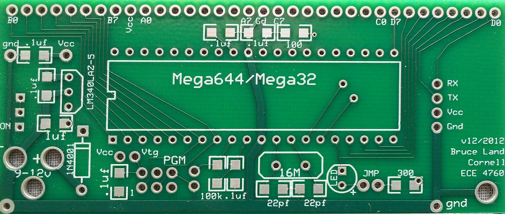
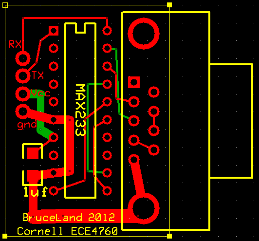
As the brain for the project, we built a target board for Atmega644 chip. The target board itself was designed by Bruce Land, and the layout is as follows (images taken from course website):
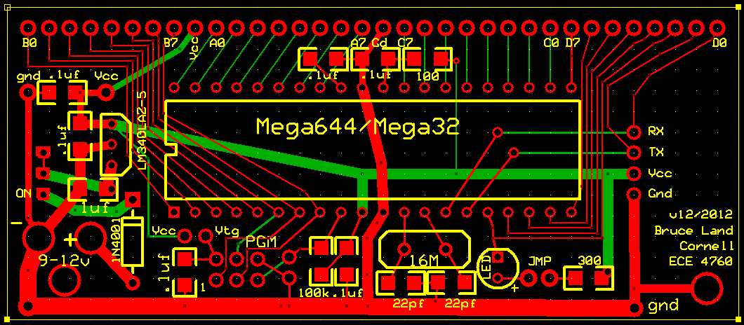
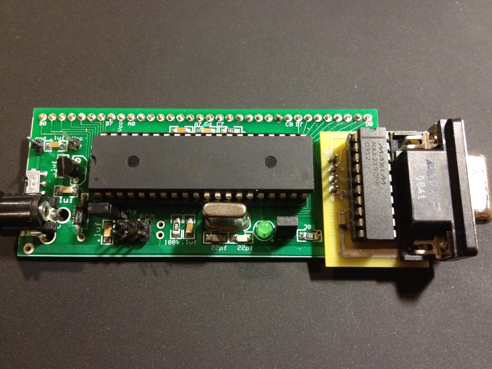
Here is the target board we built:
The key features of Atmega644 microcontroller that we used for this project are the three timers and the serial rs232 USART. The timers are responsible of scheduling periodical execution of various tasks (refer to "Software"), generate alarm tone, and generate PWM signal with appropriate duty cycle and frequency to control the servo motor.
The serial USART is used to communicate with the ultrasonic sensor and with the MATLAB running on a PC.
The one problem we faced was the fact that there is only one USART, and there are two items trying to connect through it. Thus, both the sensor and the MATLAB will see all the outgoing bytes. We resolved the issue by simply wrapping the data with unique header. It turns out that the sensor requires the header to be 0x22 in order initiate a distance measurement (more on this later), and therefore we assigned 0x01 for MATLAB. Thus, both MATLAB and sensor will be constantly polling for a command, but will only act upon it if the header matches.
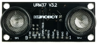
URM37v3.2 ultrasonic sensor
The URM37v3.2 sensor was purchased through DFRobot (dfrobot.com). It has its own little avr processor which executes a distance measurement when commanded by the main MCU (atmega644). Here are the front and back layouts of it:
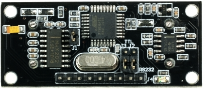
The sensor has multiple modes of operation such as serial passive control mode which always waits for command to initiate a measurement, autonomous trigger mode which makes measures every 25msec, and PWM passive control mode which outputs the measurement in an analog PWM format. We have decided to keep the sensor in the passive control mode for simplicity. The specific command that the sensor awaits to measure distance is: {0x22, degree, 0x00, checksum}. The command is sent via rs232 serial communication with 9600 baud, 8 bit data, no parity, and 1 stop bit (8N1). The degree mentioned above is an optional feature of the sensor to directly control the servo motor to that specific angle. In our case, the main atmega644 is responsible of the servo motor position, and thus the command that is sent is: {0x22, 0x00, 0x00, 0x22}.
When the sensor receives this particular command, it responds with {0x22, high distance, low distance, checksum}. Thus, the measurement can be retrieved by shifting the high distance and or-ing with the low distance: dist = (high_dist<<8) | low_dist.
Parallax standard servo motor
The servo motor requires a 5v dc power supply, and is controlled via PWM signal of roughly 50Hz. The position of the servo is determined by the duty cycle of the signal.
The servo motor can produce inductive spikes, and therefore we placed an opto-isolator between the MCU and the motor to protect the chips.
LCD
LCD is used as the main interface with the user. It is wired to all of PORTC of the Atmega644 microcontroller. The instruction on how to set it up can be found on the ECE 4760 course website
Keypad
Keypad is used for all user inputs, such as turning on the system and entering password. It has 8 pins, where the first four corresponds to rows, and the second four corresponds to columns. as a key is pressed, the intersection of a particular row and column will create a short circuit, which is used by the microcontroller to determine the key press. The detailed instruction on keypad is found on the ECE 4760 course website
Software Design
As we previously mentioned, there are three main functions that the C code runs periodically, and they are the debounce function, the system state function, and the active security function in charge of rotating motor, detecting objects, and triggering MATLAB script. Here we will describe in details about how they work. We will then talk how our MATLAB script works, as well as give brief descriptions about some remaining functions.
Debounce function
The debounce function runs every 10 milliseconds. Instead of debounce function, it should really be referred to as debounce functions. debounce_string() and debounce_request() are both needed for the keypad to work correctly. The user needs to press a certain button to start the system, and he or she also needs to press a sequence of buttons to enter a password. As a result, we must debounce each of the keypad buttons, which is done in debounce_request(), and we must support string entering. A variable key_state is used to keep track of whether a single push is expected (i.e. a command), or whether a series of pushes is expected (i.e. a password). If key_state is DONE, we expect a single button push and call debounce_request(); else, we expect a series of pushes, and debounce_string() is called.
Debounce_request() will accept one character push only, while the debounce_string() will accept a sequence of pushes, and forms a character array from them. In the meantime, the keypad is constantly checked if any button is pressed, and stores the value into butnum.
To understand butnum, we will put debounce aside for now and look briefly at how the keypad is read in the first place. Keypad button is organized by row vs column matrix, and a value is determined by looking at the intersection between them. For example, button '2' would be row 1, column 2. Thus, we will first read the row bits, followed by the column bits, and OR them to evaluate exactly which intersection was pushed. The corresponding code keypad() is presented here:
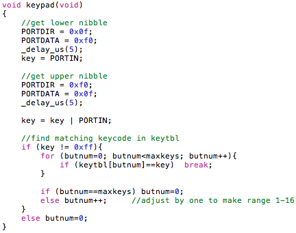
Now that we know how butnum is acquired, let us dive into how we actually debounce the keypad.
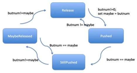
Debounce_request() is a simple state machine with four states: Release, Pushed, StillPushed, and MaybeReleased. This is covered by Professor Bruce Land in lecture and is used in previous labs. Here is a diagram of the state machine:
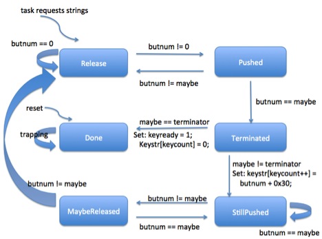
Similarly to the above is the debounce_string() function, which is practically the same as with an addition of two more states: Terminated and Done. The idea behind it is that until a certain termination key (in our case, '#') is pressed, a user is allowed to keep pressing valid parameter that could be more than one digit long. Thus, at each iteration, the state machine will check if the pressed button was '#'. If not, it will keep asking the user to enter the next digit. This is again something covered by Professor Bruce Land in lecture and implemented by us. Here is the detailed diagram describing the state machine:
As a button push or a string is captured, a variable check_flag is set to 1 to indicate there has been user input. This is crucial to the system state function, which we will talk about next.
System state function
This function, named check_task() in our C code (provided), is in charge of moving through the different stages of the security system, setting things up and preparing for the next stage.
check_task() is called every 40 milliseconds, but it only actually runs if check_flag is set to 1. check_task first checks if check_flag is set to 1. If it is, it does the appropriate operations depending on what system_state is. Variable system_state can have four values: OFF, WAIT_PASS, ON, and TERMINATED. OFF indicates that the user has not set a password and started the security system is off; WAIT_PASS indicates the user has sent command to start but has not finished inputting a password to start the security session; ON means that the security system is operating by itself (motor is rotating, sensor is actively scanning, etc.); TERMINATED indicates that the user has typed in password to disable the security system, and the system state will go to OFF by itself in a few seconds. Here is a diagram describing how the state machine works:
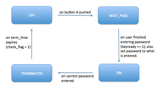
There are specific operations we do to prepare the system before it goes to the next state, such as update LCD with the appropriate message, setting password, etc. For details please see the actual code under check_task(). Also notice that check_flag is not just set by button push: although that is the case most of the times, it is also set to 1 when the system state go from TERMINATED to OFF in order for correct implementation.
Active security function
This is the function that rotates motor, request sensor to detect potential objects/intruders, and sends off sound alarm as well as triggers MATLAB script in case of object found. This function is named the_task() in our code.
Although this function is called every 200 millisecond, it only really runs if system_state is ON. What it does is that it moves servomotor by roughly 6 degrees each time, and sends a measuring distance command to the sensor by calling function measure_distance(), which we will discuss later. The resulted distance dist is set to -1 if there is no object detected, else it is the distance measured by the sensor. If the distance is within range, it beeps and triggers the MATLAB script by calling trigger_MATLAB, which takes in distance and the position of the servomotor (so we know the angle).
In our code, a variable email_time is set to 2 seconds, and its purpose is not to repeatedly send emails to owner within a very short period of time, since the sensor can detect the same object/intruder many times within 2 seconds.
EmailAndPlot.m
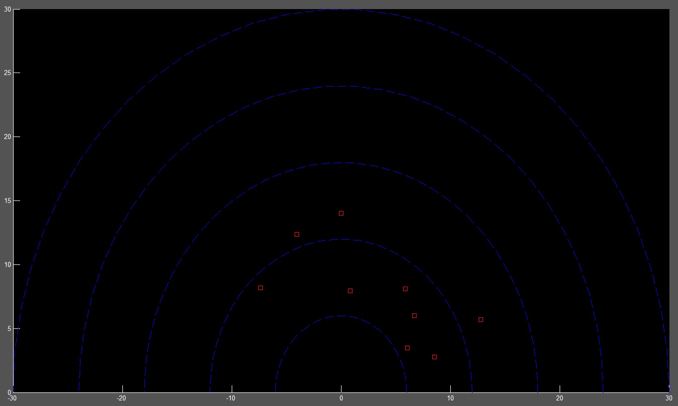
This MATLAB script is to run on the PC that is connected to the microcontroller via serial port. It constantly polls the port for a data with format {0x01, dist, angle, 0x01}. The 0x01 wrapper is there to distinguish the messages that are sent to the sensor on the same line, which are wrapped by 0x22. The script will only receive message when an object has been detected on the sensor. This script also has a nice visual radar field where upon object detection, a field will be marked red.
The most critical functionality of this script is, however, the emailing. Each time the object is detected, the script will send an email to pre-set address with the exact time of detection. This allows user to be physically away and still be notified of potential privacy violation.
measure_distance()
To initiate a distance measurement, a command, {0x22, 0x00, 0x00, 0x22}, must be sent to the sensor via rs232 serial link. This is done by sending the command one byte at a time to the UDR0 buffer as shown below. The sensor will fetch the command from UDR0 upon ready. Similarly, when the sensor returns the measurement, it is again in similar format, {0x22, high_dist, low_dist, sum}. The UDR0 is once again used as the buffer. To retrieve the distance from the data, we need to left shift the high_dist by eight and OR with the low_dist. Here is the code:

Results
Matlab radar plot
As mentioned, the program triggers a MATLAB script to plot the detected objects. Here is what the graph looks like:
Distance measurement accuracy
Our sensor calibration and utilization gave us a distance measurement with roughly 1.5 cm accuracy. Provided that we are using the sensor to detect presence of an object more so than the exact distance, this accuracy is tolerable.
Speed of detection
It takes a maximum of three seconds for the system to detect a newly present object, and to turn on the alarm. This is because the servomotor is set to cover 180 degree range, and thus it takes roughly 3 seconds for it to start from one angle and back. However, a user can easily configure the servo to a narrower angle to focus at specific area (such as doorway), in which case the sensor will detect newly present object in less than a second.
Detection accuracy
Through our tests, we believe our system is capable of detecting intruders 95% of the time, provided that sensor was placed at appropriate position. The few times that intruder get away are when they are capable of crossing past the sensor quicker than 200 msec, which is our measurement interval hard-coded into our code.
Email notification
Upon object detection, we successfully receive emails that contain the exact time when the security was triggered. This is a standard email delivery, and therefore it could take a minute or two for it to reach your inbox. When the object continues to be in the way, the system does continue to send emails. So far, we have not seen any false positive alerts.
Conclusions
Overall, this portable security system was a successful build, and we anticipate using it for the summer in NYC as we live at shared apartment against potentially bad housemates. The sensor is reliable, with convenient email-alert.
Expectation
Our original proposal was to build a simple ultrasonic radar that would shine laser at a target within range. As noticeable, we have diverged some bit from that, as we decided to make something more convenient and of potential, which is why we ended up with this ultrasonic security system. Based on the provided results from above, we believe our design possesses competitive features to many of the home security system out there, except at much more portable level.
Intellectual property
This project used several pieces of code provided by Bruce Land and/or the ECE 4760 website. First is the keypad() and debounce() tasks, provided by Bruce Land, which captures the button number pushed exactly once. Second is the 'lcd_lib.c/h' which is distributed under the GNU public license.
Ethical consideration
We have closely familiarized ourselves with the IEEE code of ethics. In particular, we have accepted responsibility in making decisions with priority placed on safety, health, and welfare of the public during our final project. One safety consideration here may be that, as our security system goes off, alarm sound is blasted and LED is programmed to flash. We have carefully calculated and planned the magnitude of our alarm during the implementation of the final project, as abrupt siren of great amplitude may cause health hazard to those with heart diagnosis.
Also, being a security product, the system must not fail once enabled. Therefore, the system must be fully powered by batteries. A standard electric outlet will not pass as any blackouts will immediately fail our security system. Thus, our system is designed such that it is operable with 9v battery for the main board and 4 AA batteries for the servo motor.
Further, we did not practice bribery to accomplish this project, and will not accept any in the future dates even if approached by one.
Legal consideration
To our knowledge, our design does not violate any legal standards, as we are only emitting short-range ultrasonic signals and not RF.
Appendix
Commented program listing
C code MATLAB codeLibraries and source code from ECE 4670 website that we used:
lcd_lib.h lcd_lib.c uart.h uart.cSchematics
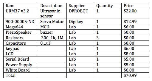
Cost details
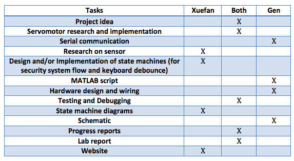
Work division
References
Datasheets we have referenced:
URM37v3.2 datasheet Parallax Servo datasheet Atmega644 datasheetWebsite we have referenced for code:
ECE 4760 course websiteVendor sites:
Digi-Key DFRobotCool People

Xuefan Zhang
Computer Science
xz227 at cornell dot edu
Gen Masuda
Electrical and Computer Engineering
gm348 at cornell dot edu