Cornell University ECE4760
319x240 VGA 256-color
Pi Pico RP2040
VGA 8-bit color on RP2040
For the 256 color version I modified Hunter's hsync PIO machine slightly to save a few instructions, modified the rgb PIO machine to pull 8 bit color, added a second rgb PIO machine, and modifed the pixel-write code for byte-wide pixel data. The second rgb PIO machine is necessary to allow line duplication required for 320x240 operation. The vga graphics display memory array is 76.8 kBytes of RAM for 320x240 pixel, 8-bit, color data. Since the PIO set command allows only five GPIO pins to be zeroed, and because I was running out of PIO memory, the drawPixel routine was limited so that it will not write in the x=319 pixel column.
-- Because of a technical limitation in the PIO state machine, resolution is limited to 319x240.
-- This version uses Protothreads 1.3, but will work with earlier versions.
-- This version is compatable with LWIP because the mapping to DMA channels uses dma_claim_unused_channel.
The color for each pixel is encoded with 3 red bits (7:5), 3 green bits (4:2), and two blue bits (1:0). To help specify color there is a rgb(r,g,b) macro that takes red,green,blue triplets and returns the bit-packed hex color.
The constants RED, GREEN and BLUE are defined in the graphics header file and act as bit-masks.
#define rgb(r,g,b) (((r)<<5) & RED | ((g)<<2) & GREEN | ((b)<<0) & BLUE )
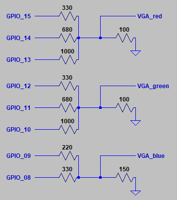
The VGA monitor lines are driven as shown below.
Feel free to adjust the resistor values for color that you prefer:
- GPIO 16 ---> VGA Hsync
- GPIO 17 ---> VGA Vsync
--------------
- GPIO 08 ---> 330 ohm resistor ---> VGA Blue lo-bit |__ both wired to 150 ohm to ground
- GPIO 09 ---> 220 ohm resistor ---> VGA Blue hi_bit | and to VGA blue
--------------
- GPIO 10 ---> 1000 ohm resistor ---> VGA Green lo-bit |__ three resistors wired to 100 ohm to ground
- GPIO 11 ---> 680 ohm resistor ---> VGA Green mid_bit | and to VGA Green
- GPIO 12 ---> 330 ohm resistor ----> VGA Green hi_bit |
--------------
- GPIO 13 ---> 1000 ohm resistor ---> VGA Red lo-bit |__ three resistors wired to 100 ohm to ground
- GPIO 14 ---> 680 ohm resistor ---> VGA Red mid_bit | and to VGA red
- GPIO 15 ---> 330 ohm resistor ----> VGA Red hi_bit |
--------------
- RP2040 GND ---> VGA GND
Schematic in LTspice format.
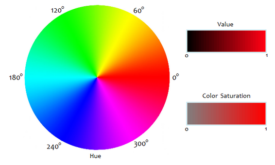
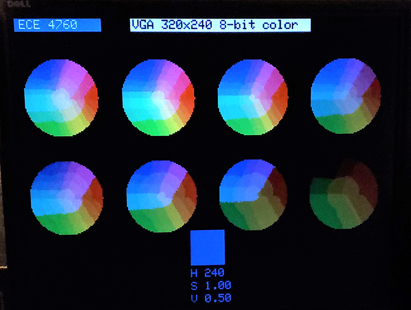
There is also a HSV to rgb converter function which allows you to specify hue, saturation, and value (brightness).
As shown below, hue values are 0- 360 degrees, while value and saturation are floats from 0 to 1.
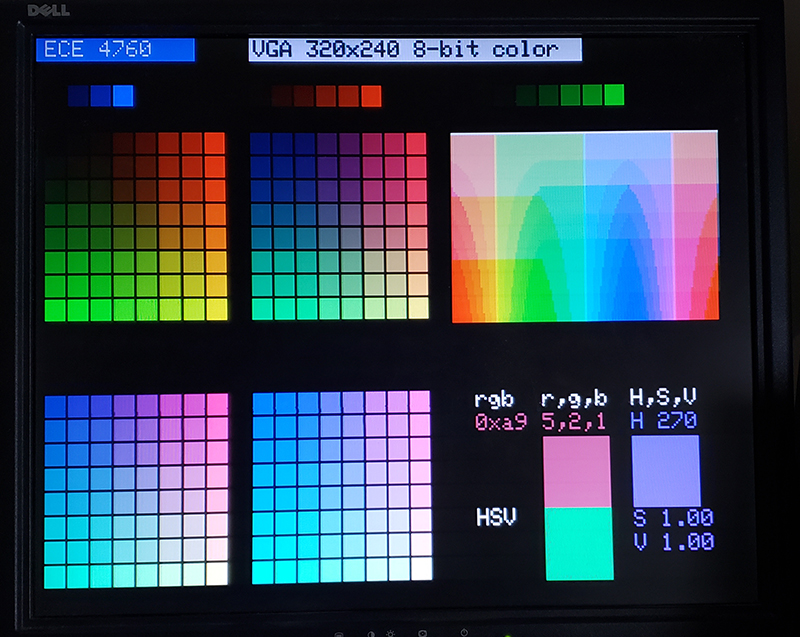
The resulting color map is shown below. Each 8x8 panel is one value of the blue channel (0-3). Red increases (0-7) to the right of each panel. Green increases (0-7) downward in each panel. To the right is a slice of hsv space at value=1.0, with saturation=0.0 at the top and 1.0 at the bottom. The hue angle varies from 0 at the left to 360 at the right. At the botom-right of the screen, the square marked HSV runs an animation of the hue color circle at saturation=value=1.0. A serial thread asks the user for a color triplet (5,2,1 in the image), then draws a filled rectangle of that color. The serial thread then asks for a hsv triplet(270, 1.0, 1.0 in the image) and draws that.
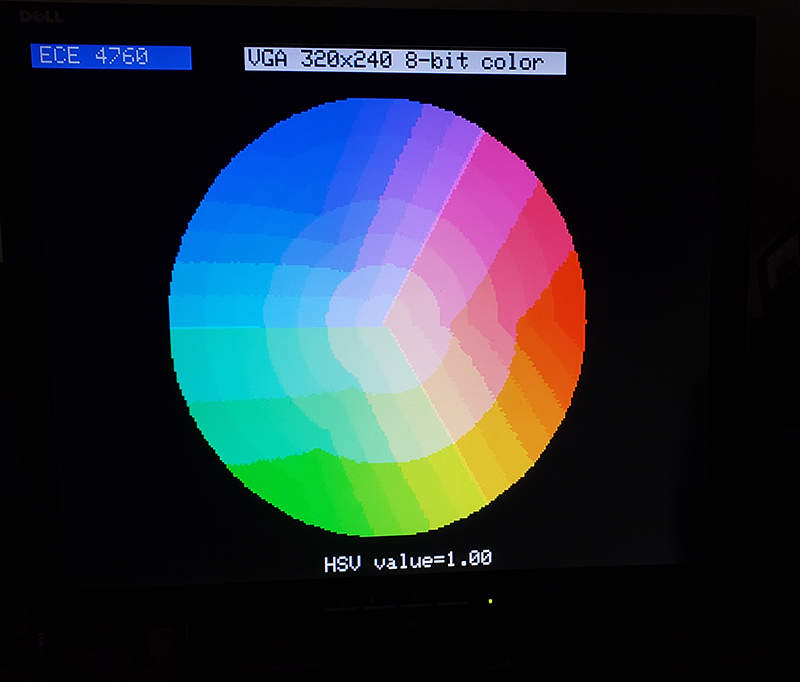
Better display of HSV color maps
HSV color spaces are usually displayed in polar coordinates, not rectangular, like the image above.
These examples clearly show off the quantization of the available colors, but in polar format.
Code for interactive full screen HSV polar plot..
You will need to modify the Cmakelist file in the project above to point to this source file.
The serial interface is used to set the value.
Code for eight slices of different HSV values=[0.99, 0.9, 0.8, 0.7 0.6 0.5 0.4 0.3]
You will need to modify the Cmakelist file in the project above to point to this source file.
Serial interface allows user to specify one HSV triplet to display at the bottom of the screen.
* RESOURCES USED:
* - PIO state machines 0 to 3 on PIO instance 0
One machine for hsync generation, one for vsync generation.
Two machines to trigger DMA channels to move pixel data from memory to the monitor.
* - DMA channels 0, 1, 2, 3 data send to two PIO machines
Channels 0 and 2 send the data. Channels 1 and 3 reset channels 0 and 2 respectively.
* - 76.8 kBytes of RAM (for pixel color data)
* color encoding: bits 7:5 red; 4:2 green; 1:0 blue
* Code summary:
* Protothreads v1.1.1
* VGA interface and setup
* graphics demo thread
* serial thread to set the color of two boxes using r,g,b and h,s,v
* the usual blinky thread for a hearbeat
Copying an image from PC to PICO
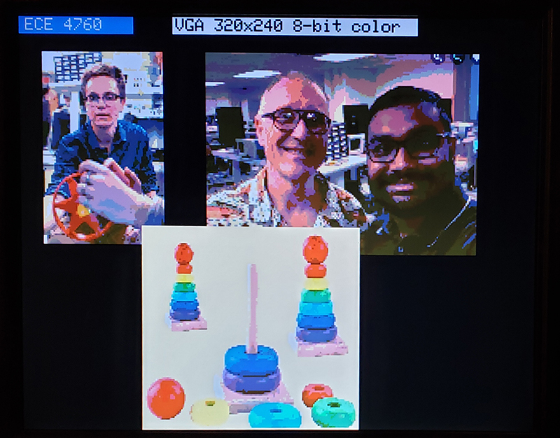
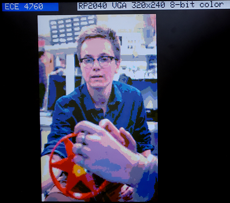
To test how well the 256 color system can show an image I wrote an Octave (Gnu Matlab clone) script that sends an image to the PICO via serial connection. The PICO runs a very simple state machine that detects start-frame, start-line, and end-frame commands, and a draw-pixel command. Optionally, the upper-left corner location of the image can be specified in the range of 0 to 255 horizontal and vertical. The protocol was designed to minimize serial traffic because drawing speed is determined by serial baud rate. Almost all the commands sent are draw-pixel commands, which were encoded as a single 2-digit hex number, representing 256 colors. The frame-control commands become 3-digit hex numbers for serial transmission. The image below shows three images on the PICO VGA display. The color mapping seems to do OK for primary colors and different skin tones, but is easy to hack in order to emphisize different color ranges. The current map increases the intensity by one (out of 8) at high and low intensities on the red and green channels. The image of hunter is duplicated at higher resolution to better show the mapping.
I wrote the image send routine in Octave because I am familiar with Matlab, but a Python version would be nice. Converting Octave to Matlab involved several trivial, but annoying, changes. Transmission starts by sending a hex 0x100, then waiting a few milliseconds for the state machine on the PICO to start. Optional x-position and y-position commands are then sent as 0h4xx for the x start location, where the xx is the actual position, and then send 0h8yy for the y start position. Each line of the image starts with a 0x200, then every pixel in the line is send as 0hzz, where zz is the actual color in 3:3:2 format. The drawing time for the towers image (127x135 pixels) below was about 6.2 seconds, or about 2800 pixels/sec. The serial link is running at 115,200 baud, or 11,520 characters/second. Each pixel transmits two numerical digits, and a '\r', or three characters total. That rate would predict around 3800 pixels/second, so there is some overhead equivalent to one character time per pixel.
C code, Octave script, Matlab r2016 script
Copyright Cornell University May 26, 2025