Cornell University ECE4760
Micropython on RP2040
Bruce Land
Introduction
Topics below mostly center around adding features to Micropython which are not included (yet) in the port, such as DMA support, and detailed control of ADC and PWM hardware. There is also information on system setup, the builtin cooperative threader, and code generation options, including the inline ARM assembler, and inline PIO assembler.
Setup for MicroPython
Getting the system running requires the micropython image UF2 file to be downloaded to the board. Follow the simple directions on the linked page. Once you have installed micropython (MP) you can connect to the board with a terminal program, but Thonny is a simple IDE which includes an editor, downloader, file handler, and console.
After installing Thonny, setup the connection to the board with:
- in Tools > Options > Interpreter Tab
Choose: micropython(raspberry Pi PICO)
Choose: USB serial device (with appropriate device name)
- in Run menu choose: Stop/restart
at this point you should see a python >>> prompt near the bottom of the window.
- In the edit pane paste in:
  from machine import Pin, Timer
  led=Pin(25,Pin.OUT)
  tim=Timer()
  def tick(timer):
     led.toggle()
  tim.init(freq=2.5,mode=Timer.PERIODIC,callback=tick)
- In Run menu choose: Run current script
The LED should blink if everything is correctly connected.
- <cntl>c normally stops a program, but the test program starts a interrupt-service-routine.
<cntl>d will force a soft reset and kill the ISR.
The command tim.deinit() also stops the timer-triggered routine
- The ISR runs at 10KHz, but fails at 100KHz and HANGS the system!
You have to unplug/plug the PICO to restart! My guess is that the ISR takes more than 10 microseconds and never actually exits if the ISR rate is too high. To test this hypothesis paste in:
    from machine import Pin, Timer
    led=Pin(15,Pin.OUT)
    x=0
    while (x<300000):
       led.toggle()
       x += 1
This
produces 24.6 KHz square wave with around 5% jitter=> loop at ~50 KHz or around 20 microsec/per loop.
- Thonny can save a script directly to the MCU flash drive and can erase a file. If you save test.py, then at the command line type: import test it will run form the local file system.
- Choosing Tools>Open system shell
opens a console directly to the >>> prompt.
To reconnect Thonny, you will have to close the console and restart the connection to the PICO.
PIO interface to micropython
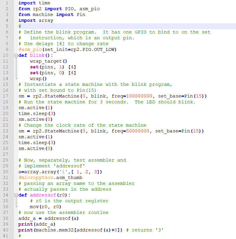
To get faster i/o you need to use hardware and not python loops. A very interesting feature of this chip is an 8-way parallel, hardware, state machine dedicated to fast i/o processing. Each of the 8 processors can run simple, deterministic, assembler programs (NOT ARM assembler, although that is also available). I stripped down the simplest example program to see how fast it would toggle a pin. The original example blinks the LED at a human rate. The folowing toggles a pin at 25 MHz! The clock frequency of the state machine can be set as high as 125 MHz (the system clock frequency). In the blink routine, the wrap statements act as a zero time, unconditional jump.
The set commands set/clear a pin, while the [1] represents a delay parameter. The result is one state machine cycle for each set, followed by a one cycle delay after each set, for a loop-time of 4 cycles. At 100 MHz, that is a 25 MHz squarewave.
The main program just turns on the statemachine for 3 seconds. If you delete the two [1] delays, the frequency will be 50 MHz.
  import time
  from rp2 import PIO, asm_pio
  from machine import Pin
  #
  @asm_pio(set_init=rp2.PIO.OUT_LOW)
  def blink():
     wrap_target()
     set(pins, 1)   [1]
     set(pins, 0)   [1]
     wrap()
# Instantiate a state machine with the blink program, at 100MHz, with set bound to Pin(15)
  sm = rp2.StateMachine(0, blink, freq=100000000, set_base=Pin(15))
# Run the state machine for 3 seconds and scope pin 15.
  sm.active(1)
  time.sleep(3)
  sm.active(0)
High speed interface: DVI from RP2040
The ARM assembler
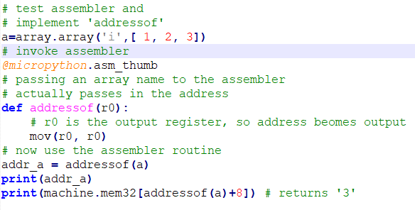
Micropython supports the ARM-Thumb assembler instructions. CPU registers R0-R7 can be used by the assembler, with function inputs in R0-R2 and function results being returned in R0. Also, when you name an array as an input parameter to an assembler funciton, python actually passes in the address to the array. To test this, I coded up a single instruction assembler function which returns the absolute memory address of an array. Python does not really want you to know about addresses, but DMA controllers need pointers to arrays to move data. The following routine just takes the input in R0, copies to itself, and exits, returning the address of the input array name. (formatted code)
# test assembler and
# implement 'addressof'
a=array.array('i',[ 1, 2, 3])
# invoke assembler
@micropython.asm_thumb
# passing an array name to the assembler
# actually passes in the address
def addressof(r0):
    # r0 is the output register, so address beomes output
    mov(r0, r0)
# now use the assembler routine
addr_a = addressof(a)
print(addr_a)
print(machine.mem32[addressof(a)+8]) # returns '3'
The complete two-assemblers (PIO and ARM_thumb) test code: code.
Note that some browsers do not like to see python code! You will need to rename the *.txt file.
Right-click the link and choose save link as...
(An image of the code.)
Code generation options in micropython
Micropython (MP) generates a bytecode executable by default.
Bytecode is compact, but slow compared to inline code. There are a least three other code generators. (see maximizing speed). The native code generator takes unmodified MP and generates a mix of inline and MP calls. The viper code generator requires some modifications/simplifications of MP source, including variable typing in some cases. It can generate inline assembler in some cases, but cannlot optimize across function calls. The assembler code generator allows you to enter ARM-M0 Thumb assembly code, linked by a simple memory map to the rest of the MP code.
I wrote a program to start testing these options, as well as other timing in MP.
(
As usual, Windoze does not like to download Python, so you will need to rename it.
)
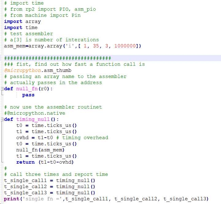
- Function calls seem slow, so I wrote a null function which simply returns, and timed it. It turns out that function calls get faster over several invocations. The code imports the time utilities and the array functionality, the invokes the null function three times. The times vary, but the first, second, and third invocations typically have times of 35, 12, and 10 uSec. The array type packs elements in the same way that C does and is used to communicate with assembler.
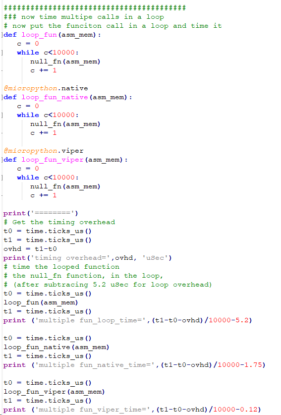
- Any real program is going to put functions into a loop, so I tested the call time in the simplest possible functions, which call the null functions a few housand times. The same function was coded as default, native, and viper to compare how the call times change. The following times in uSec show that there is aa slight improvment when not using the default bytecode. This is because the bulk of the time is spent actually calling the function. But 5-6 microseconds is not too bad, about 780 cycles.
multiple fun_loop_time= 6.5367
multiple fun_native_time= 5.0878
multiple fun_viper_time= 5.0746
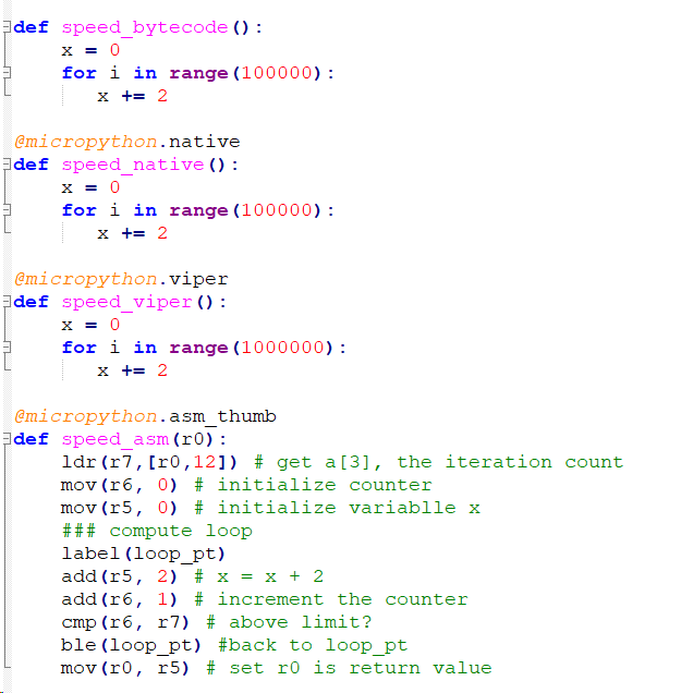
- This made me wonder how simple calculations would scale using the different code generators. I wrote four different versions of a simple increment loop and used default bytecode, native, viper, and assembler directives to compile them. The times below show a dramatic speed-up for viper-compiled code, but of course, hand coded assembler is faster. By cycle-counting the assembler code you can show that it is raw machine code.
bytecode_loop_time= 7.29907 usec
native_loop_time= 2.66444
viper_loop_time= 0.248029
asm_loop_time= 0.040052
- As a prototype for IIR filters, I wrote a looping multiply-store assembler function to see how fast it would execute. Again, cycle-counting shows that it is compiled to pure machine code. The load, multiply, store, increment, and branch took 8 machine cycles and measured ~64 nSec. If you do:
>>>
import machine
>>> machine.freq()
the frequency reported is 125 MHz, so 8 cycles should take 64 microseconds.
Micropython co-routines (cooperative scheduling) and threading (multicore)
-- Cooperative scheduling
Cooperative scheduling on the rp2040 is similar to Protothreads on the PIC32. Asyncio is a stackless, non-premptive, light-weight task handler. Some descriptive material:
Cooperative scheduling Tutorial (uasyncio module) and demo code
Documentation for version 3
Async version 3 overview
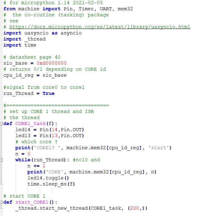
--True threading is currently very limited. From the command line (import _thread, then help(_thread)) you can see that the functionality is a subset of Cpython thread. According to the pico python SDK manual, section 3.5, You can start just one thread on the second core. However the cpu manual indicates that there is hardware support for core-to-core communication in the form of two unidirectional FIFOs, and up to 32 hardware spin locks.
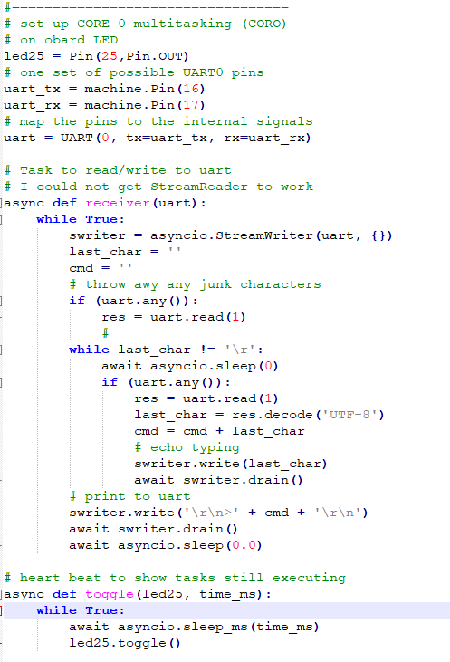
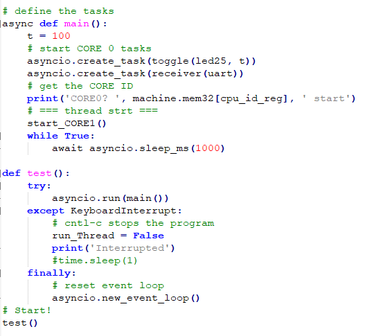
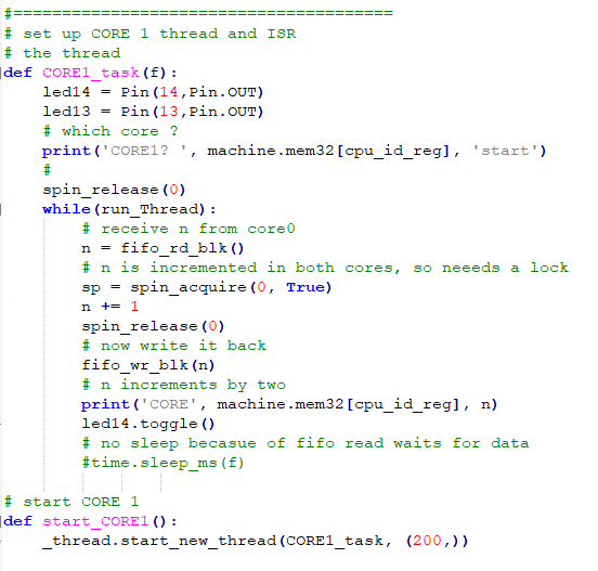
The first example starts two cooperative tasks on core0 using the asyncio library and one separate thread on core1. Programs on each core can determine which core they are running on by reading a memory address. The first part of the code defines the SIO base address, which happens to be the cpu id, and defines the core1 functions. Core1 just toggles an LED and prints out the core id. The second part defines the two asyncio, cooperative tasks running on core0. One task handles i/o to UART0, and the other blinks the onboard LED. The third part starts the two syncio tasks on core0 and the thread on core1, and allows for stopping the program with cntl-c on the REPL console. On both cores, the print command prints on the REPL (USB connection), and the streamwriter on core1 prints to UART0.
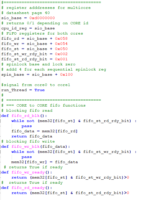
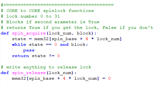
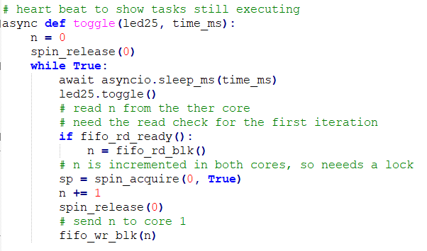
The second example tests the inter-core FIFO communication and inter-core spinlock hardware. Each core can write to one FIFO and read from the other FIFO. Each core has a FIFO read address, FIFO write address, and FIFO status, with bits to indicate that space is available to write, and that data is available to read. We need at least five functions, FIFO_read, FIFO_write (both bolcking), FIFO_read_status, FIFO_write_status, and FIFO_purge. FIFO_purge insures that there are no items in the FIFO left over from another program. The spinlocks require two functions, spin_acquire and spin_release. The spin_acquire function takes a lock number, 0 to 31, and can be either blocking or nonblocking. The code uses spin locks to protect a varialbe incremented by both cores. The FIFOs send the variable back and forth between the two cores. The overall effect is to increment the variable by two every time it is printed to the REPL console in CORE1 (CORE1 code). One of two tasks on CORE0 bounces the variable back to CORE1. To avoid deadlock after another program runs, the task initially clears the spinlock and checks to see if there is data in the FIFO.
The third example (3/15/2021) looks at communication between cores using shared memory. There are at least three ways to share memory. You can define an array in a task on one core, then pass the pointer (ctypes module; addressof()) via FIFO. You can define an array outside of a task, then jus use its name and index on both cores. You can declare a variable global, then use it on both cores.
The SIO Hardware divider (but note that MIcropython uses this natively to divide)
The SIO contains a 8-cycle hardware divider for each core. I wrote test code for it in micropython, then coded it again as a assembler program to test speed. If you stick to python, it is faster to just use the integer divide operator, //, than to invoke the hardware divider directly. The code shows how to directly touch hardware registers. Every time you load a divisor or dividend into the hardware divide inputs, a calculation is started. You can check a done-bit, or just wait 8 cycles. One test result is below. Dividing 37/6 give 5, with remainder 1. The assembler loop time is 168 nSec, of which 72 nSec is the actual divide.
HW div 7 36 5 1
asm_divloop_time = 0.16851 count= 100000
asm div 7 36 5 1
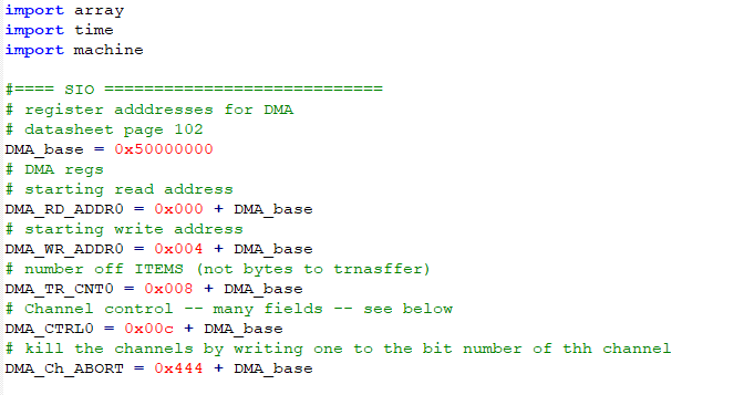
DMA direct memory access
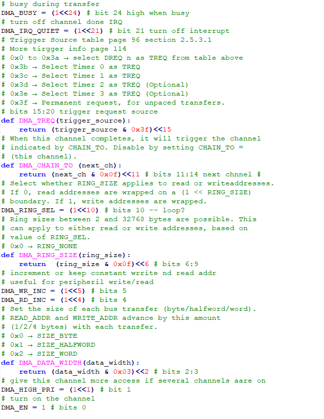
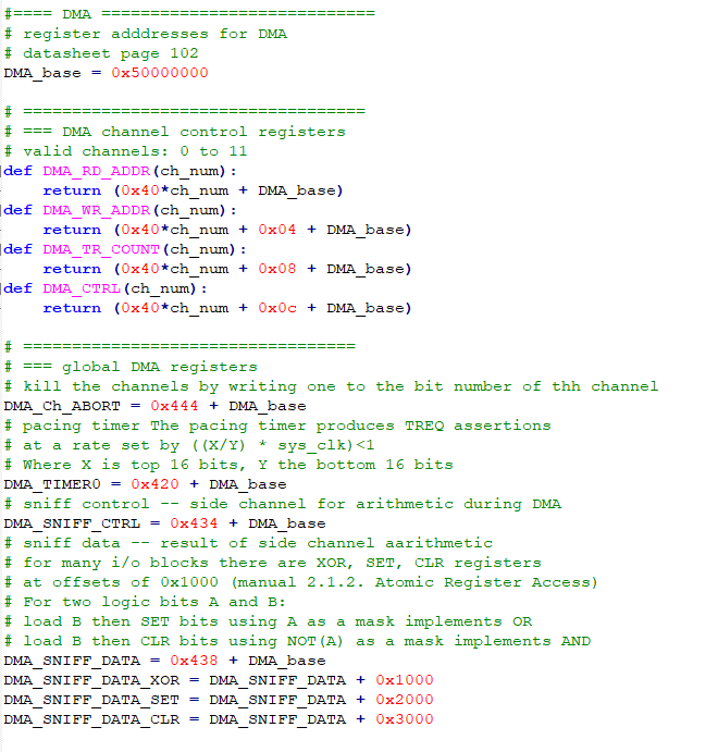
Python does not really want you to know about addresses, but DMA controllers need pointers to arrays to move data. The array data type packs data sequentially, like C, and is adressable. A one line assembler program(see above) extracts the address of the zeroth element of an array, and the other elements can be accessed from this base pointer by addition.The DMA system has LOTs of options, including ability to loop on a section of memory, send one address repeatedly (perhaps from a peripherial), chain channels, start a transfer triggered by one of about 60 events, and transmit 8, 16 or 32-bit wide data. The data rate is very high, approaching one transfer per clock cycle.
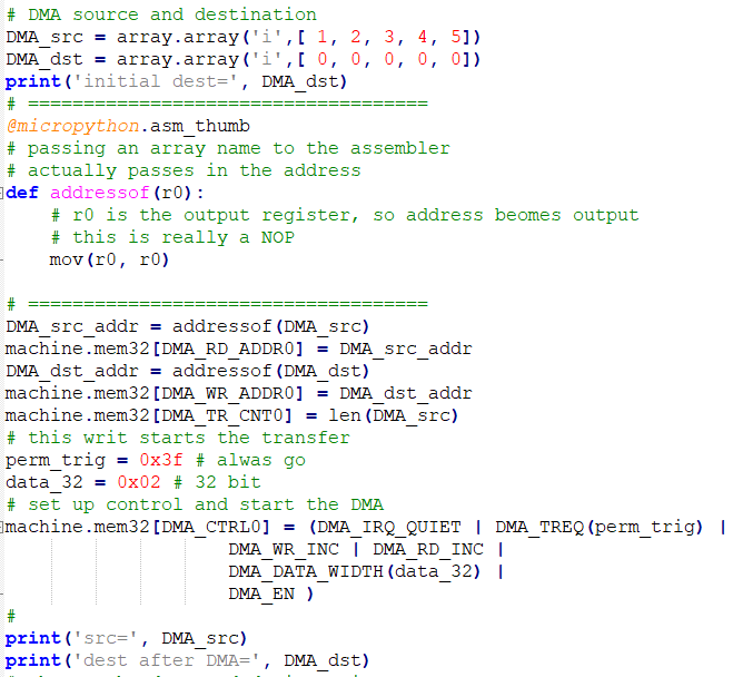
-- The first example just copies one array to another. The code just sets up the options for channel control. First the addresses of the control registers, then the configuration bits. Then, Two arrays are defined, their addresses determined, and channel zero configured for no-interrupt, permanent trigger, read and write increment, and a data width of 32-bits.
DMA_src_addr = addressof(DMA_src)
machine.mem32[DMA_RD_ADDR0] = DMA_src_addr
DMA_dst_addr = addressof(DMA_dst)
machine.mem32[DMA_WR_ADDR0] = DMA_dst_addr
machine.mem32[DMA_TR_CNT0] = len(DMA_src)
# this writ starts the transfer
perm_trig = 0x3f # alwas go
data_32 = 0x02 # 32 bit
# set up control and start the DMA
machine.mem32[DMA_CTRL0] = (DMA_IRQ_QUIET | DMA_TREQ(perm_trig) |
                    DMA_WR_INC | DMA_RD_INC |
                    DMA_DATA_WIDTH(data_32) |
                    DMA_EN )
DMA-to-PWM sinewave synthesis
Using more features of the DMA channels allows us to trigger a DMA transfer form a peripherial, in this case, the overflow of the counter on a PWM channel. All of the channel trigger sources (except for permanent trigger and timers) are in the table below. Note that the numbers are decimal, not hex. The timer triggers (in hex) are:
0x3b → Select Timer 0 as TREQ
0x3c →Select Timer 1 as TREQ
0x3f → Permanent request, for unpaced transfers
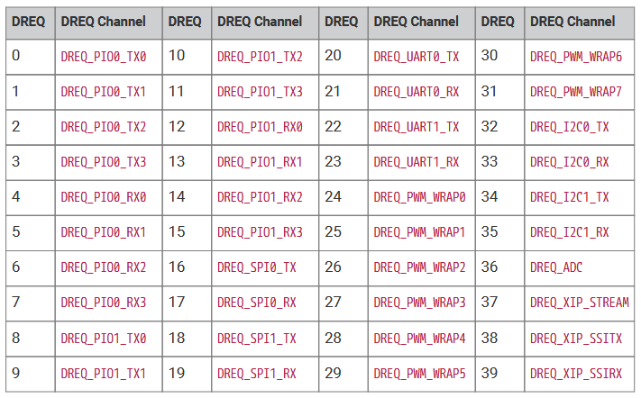
For this example, we will use TREQ source 25 (DREQ_PWM_WRAP1) to trigger DMA channel zero.The source address for channel zero will be the adddress of the sine buffer memory. The destination address will be fixed at the PWM slice one compare register. The transfer count will be the length of the sine buffer. DMA channel zero will chain to DMA channel 1 after the entire sine buffer is sent. DMA channel 1 will have a source address equal to the address, of the address, of the sine buffer. It will have a destination address of the DMA channel zero source address register, and a tranfer count of one word. DMA channel 1 will reload the source address of channel zero, then chain back to channel zero. The effect is that the sine waveform buffer will be sent continuously to the PWM. Running the PWM at full cpu frequency, with a top-count of 256 (8-bit resolution), works out to a PWM frequency of 500 KHz. With a sine buffer of length 256, we can generate a very low distortion (better than -40db) sine at 1900 Hz. Making the table shorter, to length 32, means that we can generate sine waves of about 15 KHz, with distortion still below -30 db.
The code is rather lengthy because of all the low-level setup. There is currently no direct python support of DMA so all configuration is at the big-bang level.
I did not like the python PWM abstraction, so I wrote my own to more easily set the PWM period. After setting up all of the bit-twiddling, I turned on DMA channel 1, then DMA channel zero, and finally the PWM to start everything (with the first overflow trigger).
DMA-to-PWM sinewave with settable frequency
For this example, we will use TREQ source DREQ_TIMER0 = 0x3b to trigger DMA channel zero. The timer refered to is DMA timer 0, which has settable frequency as X/Y<1 where X is the top 16 bits of a register, and Y is the bottom 16 bits. It is easy to show that the settability of the frequency is very good at audio frequencies, with a useful range of 7 Hz to 15 KHz. The rest of the DMA setup is the same as the last example. The algorithm for going from a desired output frequency, Fout, to the values of X and Y is slightly involved. For a sine table of length L, and cpu clock frequency of Fclk:
Fout = (Fclk/L)*(X/Y)
The two settable variables are X and Y, but they are not independent, and must be integers. The solution I used is to set Y to maximum value (0xFFFF), then solve for the integer X0, which will systemmatically cause Fout to be a little low. The next step is to lower Y slightly to set the closest possible frequency. To do that we are going to Taylor expand:
1/(0xFFFF - ΔY) as (2-16)/(1 -(2-16* ΔY)) yielding (2-16)*(1 +(2-16 * ΔY))
As long as ΔY<211 the approximation is good to 0.1%.
Now the output frequency can be written as
Fout = (Fclk/L)*X* (2-16)*(1 +(2-16 * ΔY))
The steps are: solve for X to give lower bound frequency, then compute a small correction.
X0 = Fout/Fclk * L * 216
ΔY =( Fout - Fout(int(X0)))/Fclk * L * 232/int(X0)
So the python code looks like:
#get exact X
X0 = (Fout/Fclk) * Ltable * 2**16
# compute actual freq using integer part of X
Fx = Fclk*int(X0)/(Ltable * 2**16)
# Taylor expanson for delta Y
dY = (Fout-Fx) * Ltable * 2**32 /(Fclk * int(X0))
machine.mem32[DMA_TIMER0] = (0xffff-int(dY)) | (int(X0)<<16)
A slight rearrangement of the PWM setup allows both the A and B outputs from PWM slice 1 to produce separate signals, in this case, sine waves in quadrature.
DMA-to-PWM sinewave looped to ADC-to-DMA-to-PWM
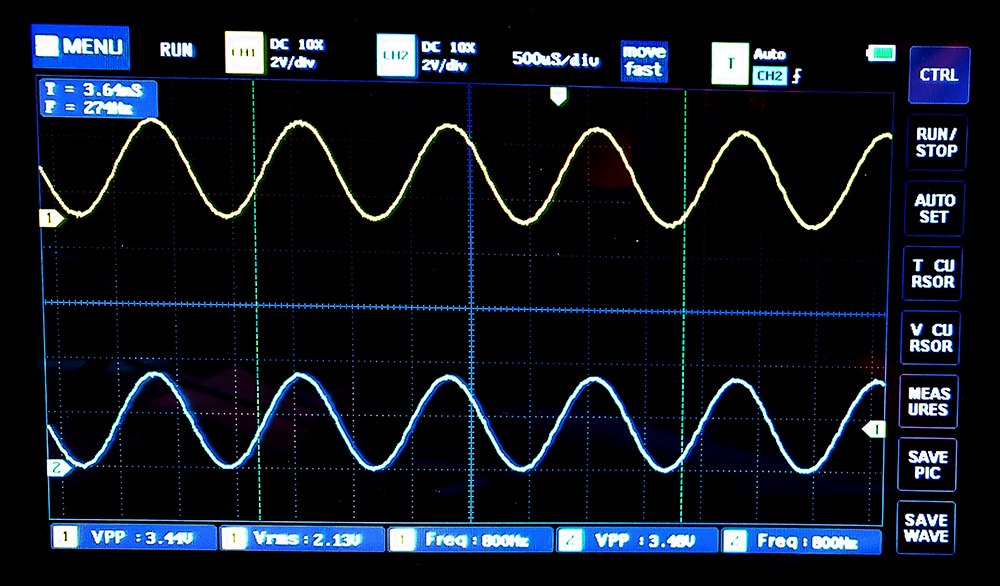
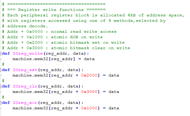
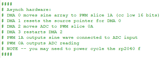
The settable frequency sine wave described in the previous example was used as a source to drive an ADC input. The ADC was set up as the trigger for a DMA channel which transfered the measurement to a PWM channel. In the process of doing this, it was necessary to re-factor the hardware register definitions for better use of the hardware. The code has explicit functions for write, set, clear, and XOR of any IO register. GPIO registers, DMA registers, and PWM registers are named so that any channel/slice can be set up. An external circuit was built to lowpass filter two PWM channels and to connect the sinewave PWM filtered output to ADC channel 0 (GPIO 26). A comment in the code describes the circuit. Another comment summarizes the cpu-asynchronous hardware used. The only function of the main python program, after setting up all the async hardware, is to ask the user what frequency the sinewave should be. The image below shows the sine wave output in blue and the ADC-to-DMA-to-PWM loop back in yellow.
DMA inline arithmetic functions
-- The data sniff function can monitor a channel and perform operations on the data flowing by. The intention is to allow fast calcuation of check-sums, but the sniffer can also do 2's complement addition on the data flow. The sniff data register can be zeroed between DMA bursts, or can be preloaded with a value to be added. The sniff control register can be set to perform CCITT CRC in four forms, summation, and XOR reduction. The register can be read normal or bit-inverted. In addition, like all i/o block registers, the sniff data registers supports transport-triggered operations which can clear, set, or XOR bits when written. Using this allows AND, OR and XOR functions on single data words. The example code uses a DMA transfer to add three numbers, after first initilizing the sniff data register using transport-triggered logic operations. As usual there is a ton of setup, to get all the control bits in the right place, but then the actual implementation is short.
-- Refactoring the DMA setup code makes the code easier to read and allows use of DMA channels 0 to 11.
Interrupts in Micropython (4/29/2021)
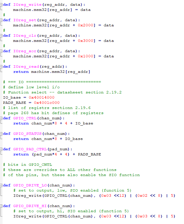
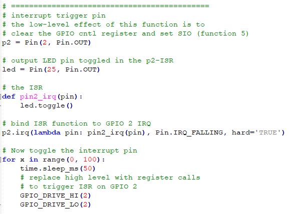
Python only knows about i/o pin IRQs (nad maybe timers). We could set up an i/o pin as an output, then use a DMA channel triggered from any TREQ source (see table above) to set/clear the pin and trigger the pin ISR. The first test code uses direct control of the GPIO registers to trigger an ISR. This is a first step in using register loads from a DMA channel. The first part of the program just sets up the i/o register definitions. The second part sets up the python interrupt, then uses low-level register writes to trigger it. In real code, the DMA channel would do the register write to trigger the IRQ.
SIO Interpolator module (2/29/2021)
The SIO has two interpolation units for each CPU. The interpolators are register-programmed, single-cycle, arithmetic devices with a number of bewildering modes. One of the easiest to understand is the BLEND mode which computes

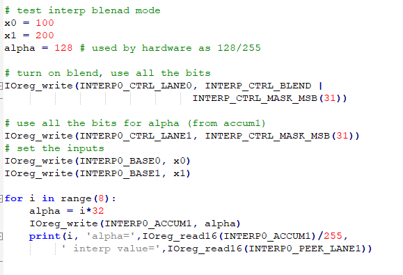
where Interpolator0 registers store the three input values, and one cycle later the output is ready. Note that alpha is actuall specified as an integer 0<=alpha<=255, understanding that the hardware treats it as divided by 256. The test code has a bulky register naming section, but a short implementation. The BLEND mode would not usually be used directly from python, but could used from assembler, or an ISR.
Interrupts and DMA transfers (4/27/2021)
There is one block of addresses for the SIO (0xd000_0000) which have a bus address only for the CPUs, but which do not appear on the system bus. It is therefore impossible for the DMA system to reach the SIO. While trying to understand this, I caused a lot of DMA bus errors. A DMA channel with set error bits is locked from execution, and Python soft-reset does not clear the bits. The bits have to be cleared by writing ones to the positions in the channel control register.
My goal for using the SIO interpolator module is to low-pass filter the ADC readings, then output them to a PWM channel. So how to get to the SIO? One possibiity is to trigger an ISR on the cpu. A DMA channel triggering on the ADC trigger request could cause an interrupt, but Python only knows about i/o pin IRQs. We could set up an i/o pin as an output, then use a DMA channel triggered from the ADC to set/clear the pin and trigger the pin ISR. A test code showing that this works.
MicroPython Notes (mostly for myself) (started 1/28/21)
- PICO micropython examples
- Micropython libraries/applications/projects --
- awesome micropython
- Paul Sokolovsky
- libraries -- may be a copy of 1
- projects -- hackster
- projects -- hackaday
- Typng help('modules') gives a list of available modules
(but excluding any modules you may have put into flash memory)
- Once you have the module names, typing help(module) gives contents of the module
BUT you need to import it first!
example:
>>> help(machine)
object <module 'umachine'> is of type module
__name__ -- umachine
reset -- <function>
reset_cause -- <function>
bootloader -- <function>
freq -- <function>
mem8 -- <8-bit memory>
mem16 -- <16-bit memory>
mem32 -- <32-bit memory>
ADC -- <class 'ADC'>
I2C -- <class 'I2C'>
SoftI2C -- <class 'SoftI2C'>
Pin -- <class 'Pin'>
PWM -- <class 'PWM'>
SPI -- <class 'SPI'>
SoftSPI -- <class 'SoftSPI'>
Timer -- <class 'Timer'>
UART -- <class 'UART'>
WDT -- <class 'WDT'>
PWRON_RESET -- 1
WDT_RESET -- 3
- Wait! What is mem8, mem16, mem32?
Mostly useful for read/write control registers
read: machine.mem32[address]
write: machine.mem32[address] = integer
- The contents of the RP2 module (PIO assembler functions)
is not well explained yet. Your best bet is to go to the examples,
because in the end, only the source matters.
- The experimental 2 core _thread
>>> import _thread
>>> help(_thread)
object <module '_thread'> is of type module
__name__ -- _thread
LockType -- <class 'lock'>
get_ident -- <function>
stack_size -- <function>
start_new_thread -- <function>
exit -- <function>
allocate_lock -- <function>
The Locktype has the methods:
>>> help(_thread.LockType)
object <class 'lock'> is of type type
acquire -- <function>
release -- <function>
locked -- <function>
Copyright Cornell University
May 26, 2021