Introduction.
You will build hardware/software to enable a small DC motor to stop at a
user-determined position. Position commands will be entered from a keyboard.
Procedure:
Build the following circuit on a prototype board. Test the Circuit thoroughly
before connecting the computer controls. For instance, make sure that the
forward and reverse signals and their compliments
are correct before connecting them to the transistors. Then make sure that the
motor runs clockwise and counter-clockwise when appropriate logic levels are
applied by hand to the direction and magnitude
inputs.

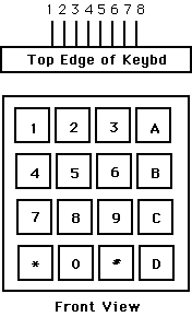
You will need to scan a keypad with the following
configuration. For the extra credit you will need to debounce it
and parse commands (see below).

Pin 1  -- row 1 2 3 A
Pin 2  -- row 4 5 6 B
Pin 3  -- row 7 8 9 C
Pin 4  -- row * 0 # D

Pin 5  -- col 1 4 7 *
Pin 6  -- col 2 5 8 0
Pin 7  -- col 3 6 9 #
Pin 8  -- col A B C D

(a) Each switch shorts one row to one column.
(b) Each pin should be connected to one
    quasi-bidirectional line of port1.
(c) Each pin should be connected by
    a 10k resistor to Vcc.
Produce a system that:
For extra credit you could:
dd* to
indicate that the motor should turn dd revolutions.