ECE 4760: Laboratory 4
Tachometer and motor controller
Introduction.
You will build a digital tachometer which displays motor speed on a LCD display
and controls the motor with user-selectable parameters to maintain constant speed. You will use ProtoThreads and write your program as tasks.
Procedures.
Serial Connection:
There will be a USB connection for serial communication between the running program and the PC, which will be running PuTTY. Set up PuTTY for 9600 baud, no parity, 1 stop-bit, no flow-control.
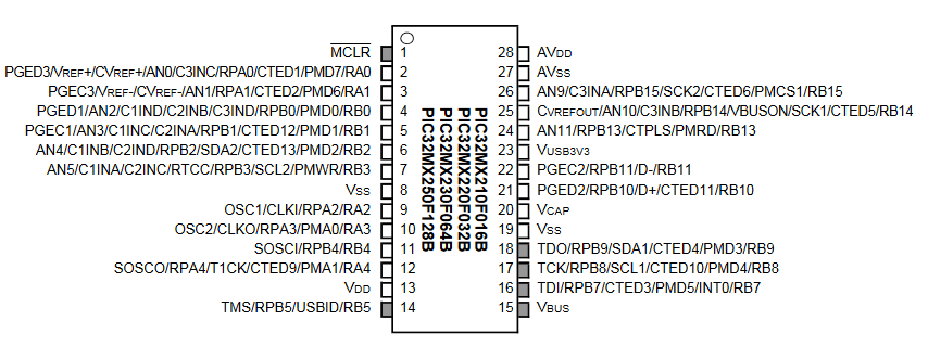
In the PuTTY config window, choose serial connection, then click serial in the left hand panel and set the parameters. Connect PuTTY to whatever serial port the USB connection configures. Use Control Panel...System...Hardware Tab...Device Manager Button...+Ports to find out which serial port is connected to the USB connection. NOTE that the default connection for U2RX (uart 2 receive) in Protothreads, and SDO1 (spi channnel 1 data) in the TFT library are BOTH mapped to the same pin, RB11, pin 22. You will need to remap one of the connections, perhaps map SDO1 to RA1!
In tft_master.c You will need to change RPB11R = 3; to RPA1R = 3; Or equivalently PPSOutput(2, RPA1, SDO1);
Use pins:
- TFT uses pins 4,5,6, 3 and 25 (RB0, RB1, RB2, MOSI1, SCLK1)
SCK1: connected to pin 25 on the PIC
MOSI (SDO1): PPS output group 2 connected to RA1 on the PIC (pin 3)
In tft_master.c You will need to change RPB11R = 3; to RPA1R = 3;
CS: connected to RB1 on the PIC
SDCS: left unconnected as I'm not using the microSD card for this
RST: connected to RB2 on the PIC
D/C: connected to RB0 on the PIC
VIN: connected to 3.3V supply
GND: connected to gnd
- Serial
- PWM output to motor controller (and scope), OC1 mapped to RA0, pin 2
- PWM output to scope for RPM, OC2 mapped to RB5, pin 14
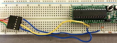
- Summary image
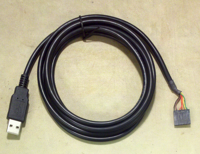
There are two styles of cable.
Use either one of:
- The black serial-USB connection is a USB cable with embedded
ft232rq USB/serial bridge chip running at 5 volt logic levels
--
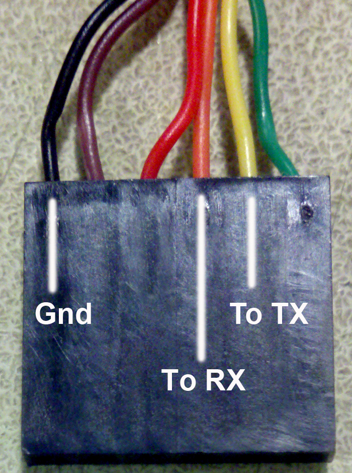
Use wires to connect the the three signals shown.
-- Do NOT connect USB Vcc to anything, unless you need 5 volt power for a circuit not associated with the MCU.
-- Connect UART receive only to the 5-volt tolerant
pin pin 22, (Diagram : 5 volt tolerant pins in gray)
-- IF you
include a 660 ohm resistor from the MCU receive pin to ground (as shown), then you can use 3.3 volt pins.
 \
\
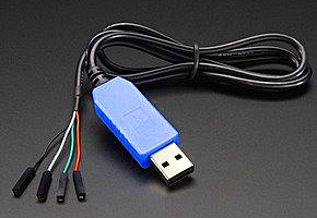
- The blue serial-USB connection is a USB cable with embedded
USB/serial bridge chip with 3.3 volt logic levels.
--
Use wires to connect the the three signals below.
-- Do NOT connect USB Vcc (red wire) to anything, unless you need 5 volt power for a circuit not associated with the MCU.
-- Connect UART receive pin 22 to the green wire
-- Connect UART transmit pin 21 to white wire
-- Connect MCU ground to black wire
Concurrency:
For this assignment you must write your code using ProtoThreads 1_2_1.
You will need to set the #define use_uart_serial option in config.h on the ProtoThreads page.
I suggest the following thread layout, but you can use anything that works for you:
- Thread 1 interacts with the PC keyboard to take user input and set up PID parameters.
- Thread 2 runs the PID control loop about 100 times/sec using speed measurements
from an ISR (see below).
- Thread 3 runs the LCD and updates it about 5/second.
- An timer capture interrupt ISR uses timer2 to measure the motor speed. As always, variables shared between threads and ISRs should declared as
volatile int.
- The output compare unit uses timer3 to produce the PWM. but no ISR is necessary.
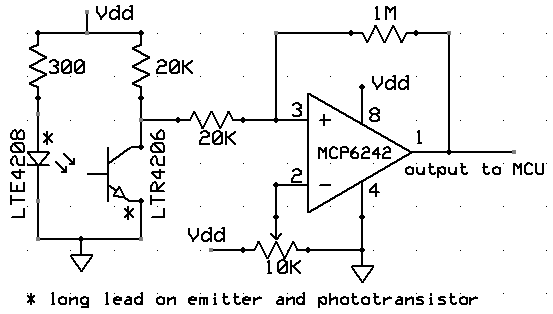
IR sensor:
We will be bouncing infrared light off the fan blades and detecting intensity
variations in the reflected light to determine the speed. The circuit below
uses a infrared emitter to shine light onto
a surface. The relected or transmitted light is detected by a phototransistor.
You will want to run the phototransistor output through an opamp comparator
to produce fast, logic-level output swings. Even if the levels at the output
of the phototransistor are compatable with CMOS logic, the rise time of the
light will be too slow for accuracy. The 10K potentiometer sets the MCP6242 comparator
threshold, the 1M resistor sets the hysteresis and may need to be adjusted.
Hysteresis makes the rising/falling edges of the waveform less sensitive
to noise.
Note the * in the following
schematic indicating the long component lead!
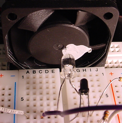
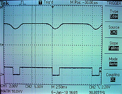
The left image below shows a fan with a dab of white paint on the hub. The clear IR emitter is pointed at the hub. The dark phototransistor is also pointed at the hub. The top trace on the right shows the output from the phototransistor. As the white paint rotates in front of the sensor, the transistor turns on and the voltage drops. The bottom trace shows the output of the opamp. The threshold should be adjusted so that the opamp switches at a voltage where abs(dv/dt) is high.
The output of the opamp could be fed directly into the capture input, as long as the opamp power rails are Vdd and ground.
Keep the opamp output away from the PWM lead coming from the MCU.
Capacitative coupling can corrupt the output of the opamp!
For debugging, you can see a slight glow in the IR emitter using your cell
phone camera because a solid state camera is sensitive to infrared light. You
may need to shield the phototransistor from the LED by slipping a small piece
of black paper between them so that the transistor sees the white paint, but
not the LED. The symptom will be that the transistor output is always low.
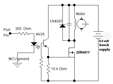
Motor Control:
You will need to drive a fan from the mcu. Fans have motors which can cause
nasty inductive spikes to wipe out the transistors in the mcu port. The
circuit shown below is fairly safe. An optoisolator completely isolates
the MCU from the motor. The diode placed across the motor shorts out spikes
when the motor is turned off. The resistor grounding the base of the phototransistor
should be set for best falltime, probably around 1Mohm. The motor capacitor
should start around 0.1uf. Increase it if there is too much spike noise on
the analog input, but be sure to use ceramic capacitors, not electrolytic.
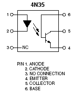
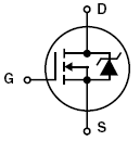
Electrolytic capacitors are too slow. The pinout of the 4N35 optoisolator
and 2SK4017 are also shown. Note that the bandwidth
of the 4N35 is very small, so use a low PWM frequency, perhaps about 1000
Hz.
A matlab program demonstrating the PID control
algorithm includes the following nonlinear effects: The sensor is modeled
as producing a new value once/revolution. The effect is to make a feedback
which is dependent on the speed of the motor, with the motor becoming more
stable at higher speed. The motor is modeled as a second-order system when
it is powered, and a first-order system when it is coasting. The controller
has saturation (maximum voltage) and rectification (no negative output). You might also look at PID Tuning and
Ziegler–Nichols method. (original paper . "Optimum settings for automatic controllers") and a critique.

Assignment
Write two to four tasks using ProtoThreads and construct a circuit which will:
- Measure the rotation rate of a small fan using IR emitter/sensor.
- Format the rotation rate and display appropriate messages on an LCD.
- Take commands from the PC keyboard to:
- Set the desired motor speed.
- Set the PID proportional gain.
- Set the PID differential gain.
- Set the PID integral gain.
- To enter values on the PC keyboard, you will use command formats like:
- Use a PID algorithm to control the speed of the motor by producing a PWM drive to the optoisolator. PWM setup example.
- Tune the PID algorithm so that you can change the speed of the motor quickly
and accurately without excessive oscillations in speed.
The user should be able to
type in a desired speed and the motor should quickly change to the new speed.
- Display a low-passed version (time constant about 0.1 second) of the PWM motor control on the scope or TFT.
- Display a low-passed version (time constant about 0.1 second) of the actual motor RPM on the scope or TFT.
You will demo all the features above to your TA.
Your program should not need to be
reset during the demo.
Your written lab report should include the sections mentioned in the policy page, and :
- A schematic of the circuit you built.
- Scope screen dumps of typical two-trace: (1) motor-control and (2) actual RPM.
Include acceleration and deceleration steps.
- A summary of the accuracy of your measurements.
How accurately can you measure the rotation speed?
- How you selected the three PID gains.
- A heavily commented listing of your code.
Copyright Cornell University
October 28, 2016
 \
\