Depending on your interests, you can build either a digital voltmeter, or a five-function fixed-point calculator.
Procedure:
NOTE: If you are using the STK-200 board be sure not to use pin 10 on the i/o connectors for ground. It is Vcc!
The DVM project requires that you use the STK-200 board. Note that the cpu is an AT90S8535. The main differences from the 4414 are
If you build the DVM, you will need to figure out a way to measure resistance. There are several possibilities:
A short code shows how to read the analog-to-digital converter using the timer 1 matchA function to pick a rate. Be sure to adjust the ARef pot on the STK-200 board so that ARef=4.096 volts. Setting ARef to 4.096 volts means that each count of the 10-bit ADC is equal to 4 millivolts, so conversion to voltage is easy. Pin 10 of the analog port is ARef. Do NOT connect anything (except the DVM) to ARef. It has very limited current drive capability. ARef also appears to drift as much as 0.4 volts after the board is turned on. Check it a few times.
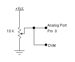
The diagram below shows the test circuit for this code. If you set the trimpot so that the input voltage to the analog port is greater than ARef (but less than or equal to Vcc), you will read back all ones from the analog to digital converter. If you somehow put a voltage greater than Vcc on the analog input, you will destroy it.

As in Lab 5,
the Keyboard:
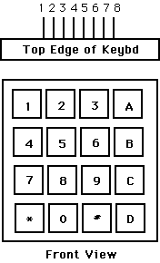
You will need to get user input from a keypad with the following
configuration.

Pin 1  -- row 1 2 3 A
Pin 2  -- row 4 5 6 B
Pin 3  -- row 7 8 9 C
Pin 4  -- row * 0 # D

Pin 5  -- col 1 4 7 *
Pin 6  -- col 2 5 8 0
Pin 7  -- col 3 6 9 #
Pin 8  -- col A B C D

(a) Each switch shorts one row to one column.
(b) Each pin should be connected to one
    bit of an i/o port.
(c) The i/o port pins will be used both
    as inputs and outputs. When they are inputs,
    they should have the pullup resistors
    activated.
As in lab 5, the Liquid Crystal Display (LCD):
LCDpin 	Connection
------  ----------
1	gnd - Port A
2	+5 volts - PortA7
3 	trimpot wiper
4	PortD6
5	PortD5
6	PortD4
7-10	no connection
11	PortD0
12	PortD1
13	PortD2
14	PortD3
You will demo the DVM or calculator to your TA.
Your written lab report should include: