You will produce a security system with keypad and LED display. The security system will be controlled by and report to a administrators PC.
Procedure:
The Keypad:
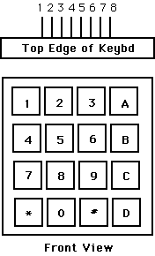
You will need to get user input from a keypad with the following configuration. Demonstration keypad scanning code is in ASM and in C.

Pin 1  -- row 1 2 3 A
Pin 2  -- row 4 5 6 B
Pin 3  -- row 7 8 9 C
Pin 4  -- row * 0 # D

Pin 5  -- col 1 4 7 *
Pin 6  -- col 2 5 8 0
Pin 7  -- col 3 6 9 #
Pin 8  -- col A B C D

(a) Each switch shorts one row to one column.
(b) Each pin should be connected to one
    bit of an i/o port.
(c) The i/o port pins will be used both
    as inputs and outputs. When they are inputs,
    they should have the pullup resistors
    activated.
Serial connection to the PC:
Be sure to read the serial communication page. The serial port on the yellow board should be connected to COM2 of the PC. You should use a simple terminal program, such as Hyperterminal, on the PC connected to COM2. The terminal program should be set to 9600 baud, no parity, one stop bit, and no flow control. You can use either demo program as a test that the RS232 connnections and terminal program on the PC are correct. Connections to the PC assume a RS232 cable with straight-through connection.
Write a program in C for the 8515 with these specifications:
When you demonstrate the program to a staff member, you should exercise the keyboard entry functions and PC commands.
Your written lab report should include: