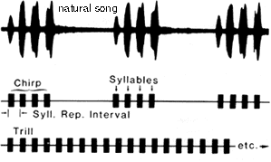
You will construct a cricket-call generator which will produce audio output of a simplified cricket call. A cricket call may be very complex, but we will limit ourselves to the following form.
The image below summerizes the definition ( from Manfred Hartbauer).

Procedure:
You will use an LCD and a keypad to set the parameters like those shown in the table below. Analog output will be in the form of a PWM signal which will be filtered using a simple RC circuit to low pass filter the analog signal. Use a big enough resistor so that you don't load the port pin, and small enough to be below the input resistance of the TV audio input (20 kohm). You should set the RC time constant to about 10 times the period of the PWM. The output of the lowpass filter will go to the audio input of the TV. The PWM signal will be sine wave bursts generated using an amplitude modulated Direct Digital Synthesis (DDS) technique. A short example shows how you might implement a DDS and amplitude modulate it.
You will need to figure out how to generate a variety of time delays and durations. I suggest the following scheme, but you may use any scheme you want. Timer 0 is used to generate the high speed PWM-based D/A signal necessary for the sine wave synthesis. The output will be through OC0 (port pin B.3). Use the PWM mode with the highest speed. This interrupt will also increment a counter to count to 1 mSec. The resulting 1 mSec time base will be used to control all other timing (in the main program, not in the interrupt).
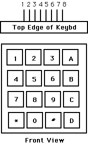
You will need to get user input from a keypad with one of two following configurations. Some keypads have the connector on the top, as shown. Some have them on the bottom. Demonstration keypad scanning code is here.

         Conn. on top     Conn. on bottom
Pin 1  -- row 1 2 3 A         Column 1
Pin 2  -- row 4 5 6 B         Column 2
Pin 3  -- row 7 8 9 C         Column 3
Pin 4  -- row * 0 # D         Column 4
Pin 5  -- col 1 4 7 *         Row 1
Pin 6  -- col 2 5 8 0         Row 2
Pin 7  -- col 3 6 9 #         Row 3
Pin 8  -- col A B C D         Row 4
(a) Each switch shorts one row to one column.
(b) Each pin should be connected to one bit of an i/o port.
(c) The i/o port pins will be used both as inputs and outputs.
    When they are inputs, they should have internal pullup resistors
    turned on.
| parameter | chirp+ silence duration | number of syllables |
syllable |
syllable |
burst frequency |
| call 0 | 20 | 1 | 10 | --- | 4500 |
| call 1 | 250 | 4 | 18 | 30 | 5000 |
| call 2 | 1500 | 50 | 8 | 20 | 6000 |
| call 3 | 1000 | 5 | 30 | 50 | 3000 |
| Range | 10 to 1000 | 1 to 100 | 5 to 100 | 10 to 100 | 1000 to 6000 |