EE 476: Laboratory 5
Digital Thermometer with fan
Introduction.
You will build a digital thermometer which displays temperature on a LCD display
and controls a fan with user-selectable turn-on temperature.
Procedure:
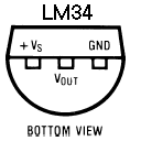
The LM34 temperature sensor produces a voltage output
of 10 mV/degree F. Note that the connections shown in the datasheet are the bottom view of the TO92 package (see below).
You will need to perfrom an analog-to-digital conversion
using the mcu to read the voltage. For optimum accuracy, you will need to amplifiy
the output of the LM34 by a factor of 2 (using an LM358
opamp) before feeding it into the A/D converter. Note that the LM358 is not rail-to-rail. For a 5 volt power supply, the output range is 0 to 3.0 volts. Filtering the opamp output
may lower spike noise, but the output impedance of the circuit you use to filter should be less than 10Kohms. Use the scope to decide if you need a filter. The most
accurate way to use the ADC requires that you use the internal voltage reference.
For each different mcu that you use, you will need to measure Aref and use the
measured value in your code.
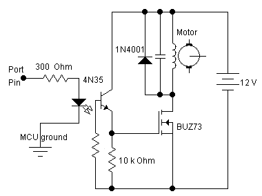
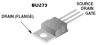
You will need to drive a fan from the mcu. Fans have motors which can cause
nasty inductive spikes to wipe out the transistors in the mcu port. The circuit
shown below is fairly safe. An optoisolator completely isolates the MCU from
the motor. The diode placed across the motor shorts out spikes when the motor
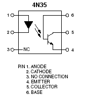
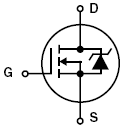
is turned off. The resistor grounding the base of the phototransistor should be set for best falltime, probably around 1Mohm. The motor capacitor should start around 0.1uf. Increase it if there is too much spike noise on the analog input, but be sure to use ceramic capacitors, not electrolytic. Electrolytic capacitors are too slow. The pinout of the 4N35 optoisolator and BUZ73 are also shown.
Assignment
Write a program and construct a circuit which will
- Measure room temperature with an LM34 and convert the output voltage to
a number using an A-to-D converter program running on the mcu.
- Format the termperature and display appropriate messages on an LCD.
- When the user briefly presses one of two buttons (labeled
increase and decrease),
display the fan set-point temperature.
- You must debounce buttons if it is necessary for relable performance.
- Make the default fan set-point temperature
(at RESET time) be greater than room temperature.
- If the user holds either the
increase or decrease button down for more than 1/2 second, the set point
is modified in the appropriate direction, at about 1 degree every 0.5 second, and displayed on the LCD.
- If the actual sensor temperature is above the set-point, turn on the fan.If
the fan is pointing at the LM34, it should cool the temperature sensor and turn
itself off.
You will demo all the features above to your TA.
Your written lab report should include:
- A schematic of the circuit you built.
- A summary of the accuracy of your measurements. You should look at noise
on the opamp output using the scope. You should also look at the stability
of the A/D converter at constant voltage input.
- A heavily commented listing of your code.
Copyright Cornell University Dec 2007