
You will produce a digital capacitance meter (DCM) which displays the capacitance in the LCD. The DCM will
measure capacitances from 1 to 100 nF.
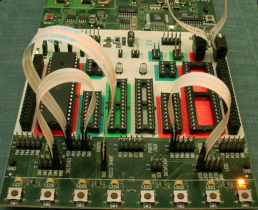
But first you need to set up a board, arrange jumpers, learn how to connect peripheral devices and use the compiler. You will first do a quick exercise to compile an existing program and watch the blinking lights. The LEDs on the board are the embedded programmers low-level, fast, debug tool.
Hardware
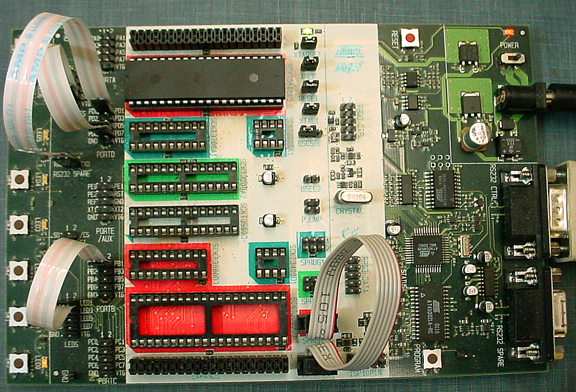
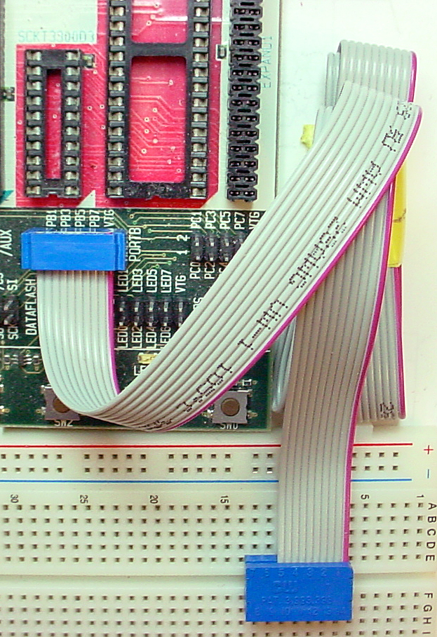
The hardware you will be using to support the MEGA-series is the Flash MCU evaluation board, a small board providing:
Software
Software you will use is freely downloadable and consists of:
More information
General hardware Procedures
Z drive! Do not creat a project on the local drive! Be sure to put all your files there and to back up daily!.
Start...Run...hypertrm from the Windows Start menu.
Connect hyperterm to whatever serial port the USB dongle configures. Use Control Panel...System...Hardware Tab...Device Manager Button...+Ports to find out which serial port is connected to the USB dongle.
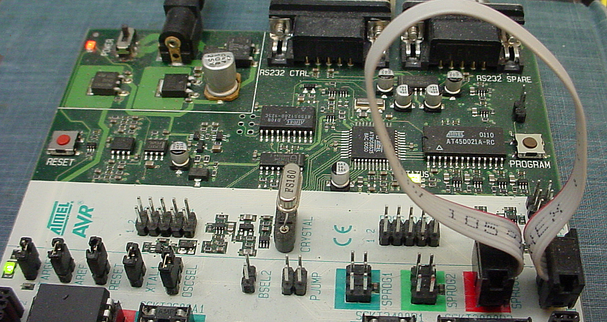
The STK500 serial port RS232 Spare will be connnected to the dongle.
Set up hyperterm for 9600 baud, no parity, 1 stop-bit, no flow-control.
z drive. This program blinks LEDs and
responds to buttons. It is organized as three task subroutines. You will
use this code to test your hardware setup.Project menu choose Project Wizard. When the dialog box
appears, choose New Project. AVR simulator and choose ATmega644, then press Finish Project-> Configuration Options -> General -> Frequency enter 16000000 because the crystal frequency is 16 MHz. Build from the Build menu. A message window will open to tell you if
there are errors in the code. Tools>Program AVR>Autoconnect menu item which will open a dialog box. In the dialog box:
Main tab, set the ISP frequency (Settings... dropdown) to 57 Khz, then press Write then Close. Mega644. Program Tab, Flash box, select the hex file generated by the compiler. The file will be in theproject folder>default folder. Press the Program button. If the program does not download to the chip, call a TA. Note that the hex file name is NOT updated for you and will default to the last project compiled on the computer.Fuses tab in the programmer window and set the SUT_CLKSEL fuse to:Ext crystal osc 8- MHz; startup time: 16k clk+65 mSec.CLKDIV8 box.JTAGEN box and answer YES in the confirming dialog. (If you leave the box checked, PORTC does not work correctly). ProgramWhen the program is running and blinking lights, you should be able to press button 7 to change the blinking rate. Uncomment all the statements necessary to enable serial communication to the PC and make sure it works. Printf statements are a useful way to debug. At this point you can move on to the actual lab exercise below.
Capacitance Procedure:
delay_ms. Using delay_us will be acceptable when you need to produce delays on the order of a few microseconds.
The Liquid Crystal Display (LCD):
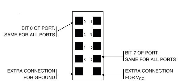
A 16 character, two line (16x2), LCD display be used as a numerical display. The display we are using has an industry-standard interface. A more detailed data sheet for a similar display shows the command set, but start by reading the demo code, not by reading the data sheet. There are several aspects of the display you should note:
| LCD pin | Mega644 pin |
|---|---|
| 1 gnd | gnd on STK500 |
| 2 Vcc | VTG on STK500 |
| 3 contrast ** | ---------------> |
| 4 rs | port C0 |
| 5 rd | port C1 |
| 6 en | port C2 |
| 7 n.c. | -- |
| 8 n.c. | -- |
| 9 n.c. | -- |
| 10 n.c. | -- |
| 11 | port C4 |
| 12 | port C5 |
| 13 | port C6 |
| 14 | port C7 |


Capacitance measurement
The approach we will use is to measure the time it takes for a RC circuit to
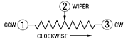
charge a capacitor to a given level. If R3=R4 in the schematic below then the level will be v(t1/2)=Vcc/2. Specifically,
we will use the internal analog comparator as shown in the following
diagram to trigger a timer1 event. Since R2 will be known, we can get C because the voltage on the capacitor v(t)=Vcc(1-exp(-t/τ)) with τ=(R2)*C.
The capacitor shown is the device you are trying to measure.
The resistor going to PortB2 should be around 100 ohms to limit current. You must choose R2
so that the capacitor charging time is not too short or too long. If it is too short you will lose measurement accuracy. It if is too long, the timer will overflow.
If you decide to print floating point numbers to the LCD you need to follow the directions in Using sprintf function for float numbers in AVR-GCC the AVRstudio directions are at the bottom of the page, but NOTE that one library is left out. The correct summary is: Open the Project>Project Configuration dialog box, then go to the custom options , then select linker options,
and then add the
-Wl,-u,vfprintf -lprintf_flt switches.
Your program will have to (in time order):
R2>100*(100ohms).
I suggest that you organize the program as follows:
Timing of all functions in this lab, and every exercise in this course will be handled by interrupt-driven counters, not by software wait-loops. This will be enforced because wait-loops are hard to debug and tend to limit multitasking.
Write a C program which will:
C = xxx nf to the LCD
When you demonstrate the program to a staff member, you should demonstrate that the capacitance is correct within the tolerance of the resistors you use. Your program should not need to be reset during the demo.
Your written lab report should include the sections mentioned in the policy page, and :