You will construct a standard Dual Tone Multi-Frequency (DTMF) generator like those used on any tonch-tone phone.
Procedure:
You will use a keypad to make a DTMF dialer with audio output to a TV. Analog output will be in the form of a PWM signal which will be filtered using a simple RC circuit to low pass filter the analog signal. Use a big enough resistor so that you don't load the port pin, and small enough to be below the input resistance of the speaker audio input (30 kohm). You should set the RC time constant to be bigger than the the period of the PWM, but not big enough to excessively attenuate the DTMF frequencies. The output of the lowpass filter will go to the audio input of the speakers. The PWM signal will be DTMF sine wave bursts generated using Direct Digital Synthesis (DDS) technique. A short example shows how you might implement a DDS. For this lab, you will need to modulate the amplitude, and you will need to run two simulaneous DDS units and sum them. The sine wave table will need to be scaled to prevent overflow. Use the timer0 fast PWM mode with the prescalar set to 1 to produce about 62500 samples/sec. This example shows how you might amplitude modulate a sine wave, but may be too slow for two sine waves. You will have to try it.
You will need to control various intervals of time and generate the PWM signal. I suggest the following timing scheme, but you may use any scheme you want. Timer 0 is used to generate the high speed PWM-based D/A signal necessary for the sound synthesis. The output will be through OC0A (port pin B.3). In PWM mode, each PWM cycle completion is signaled by the overflow interrupt. The timer0 overflow ISR is therefore used to load a new output compare value for the next audio sample. In this ISR you can also increment a counter to count to 1 mSec. The resulting 1 mSec time base will be used to control all other timing (in the main program, not in the interrupt).
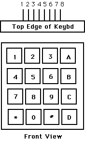
You will need to get user input from a keypad with one of two following configurations. Some keypads have the connector on the top, as shown. Some have them on the bottom. A demonstration keypad scanning code for testing your connections is here. An example of a debounce state machine for a single STK500 pushbutton (not the keypad) is included here for reference.

Connector:  top:8-pin      top:9-pin   bottom
Pin 1  ---- row 1 2 3 A    col 1       col 1
Pin 2  ---- row 4 5 6 B    col 2       col 2
Pin 3  ---- row 7 8 9 C    col 3       col 3
Pin 4  ---- row * 0 # D    col 4       col 4

Pin 5  ---- col 1 4 7 *    row 1       row 1
Pin 6  ---- col 2 5 8 0    row 2       row 2
Pin 7  ---- col 3 6 9 #    row 3       row 3
Pin 8  ---- col A B C D    row 4       row 4
Pin 9  ----              (NO CONNECT--common)

(a) Each switch shorts one row to one column.
(b) Each pin should be connected to one bit of an i/o port.
(c) The i/o port pins will be used both as inputs and outputs.
    When they are inputs, they should have active pullup resistors.
(d) On the 9-pin models, do not connect the common lead.
Hints on debugging are here.
* button erases the entire stored phone number.
# button is pressed, the DTMF signal for each entered digit is produced for 100 millseconds to simulate dialing of the digits.
There should be at least 30 millseconds of silence between each digit.
* button (or any button on the STK500) while pressing the buttons 1 through 7 should produce one of seven sine waves for as long as you hold the buttons. A table of DTMF frequencies:
| Freq | 1209Hz | 1336Hz | 1477Hz |
| 697Hz | 1 | 2 | 3 |
| 770Hz | 4 | 5 | 6 |
| 852Hz | 7 | 8 | 9 |
| 941Hz | * | 0 | # |