ECE 4760: Laboratory 1
Human reaction time.
Introduction.
You will produce a reaction time measurement device which signals a user by flashing a light and making a short sound, then recording the time it takes for the user to push a button. The user's reaction time will be displayed on an LCD and the minimum measured time recorded in eeprom. The site Human Benchmark suggests that the mean reaction time is around 220 millseconds, with a standard deviation of around 60 mSec. But first you need to set up a board, arrange jumpers, learn how to connect peripheral devices and use the compiler. You will first do a quick exercise to compile an existing program and watch the blinking lights. The LEDs on the board are the embedded programmers low-level, fast, debug tool.
Hardware
The hardware you will be using to
support the MEGA-series is the Flash MCU evaluation board, a small board providing:
Software
Software you will use is freely downloadable and consists of:
More information
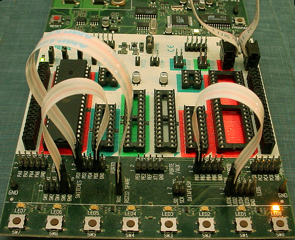
General hardware Procedures
- Make sure the evaluation board is connected to power and to the PC as specified
in the evaluation board description. Turn on the power supply with the switch
on the board. An LED in the middle of the board should cycle from red to yellow
to green. For the first part of this lab, there should be jumpers on the PortB to the
LED header and on PortD to the switch header. Ask your instructor for help
if these are not installed. There should be a two wire connector from pins D.0 and D.1 to the RS232 jumper.
- Make sure the crystal on the STK500 is actually 16 MHz.
- There will two serial connections to the STK500. One for programming the Mega644 and one for serial communication between the running program and the PC, which will be running PuTTY. Set up PuTTY for 9600 baud, no parity, 1 stop-bit, no flow-control.
In the PuTTY config window, choose serial connection, then click serial in the left hand panel and set the parameters. Connect PuTTY to whatever serial port the USB dongle configures. Use
Control Panel...System...Hardware Tab...Device Manager Button...+Ports to find out which serial port is connected to the USB dongle.
The STK500 serial port RS232 Spare will be connnected to the dongle.
- Put all files on your
Z drive! Do not creat a project on the local drive! Be sure to put all your files there and to back up daily!.
- There should be a shortcut to AVRstudio on the desktop or start menu.
- After you define a new project, you can add a C source file and edit it. This first example code is just for testing the hardware setup and to learn how to use AVR studio. Later you will use a different program to measure timer intervals, which is the basis for lab 1.
- Save this code into your
z drive. This program blinks LEDs and
responds to buttons. It is organized as three task subroutines. You will
use this code to test your hardware setup.
- In the AVRstudio
Project menu choose Project Wizard. When the dialog box
appears, choose New Project.
- In the new dialog box choose a GCC project, give the project a name, and indicate a source file to use. Choose a location on your Z drive to store the project.
- In the next dialog box choose to debug with
AVR simulator and choose ATmega644, then press Finish
- In the menu item
Project-> Configuration Options -> General -> Frequency enter 16000000 because the crystal frequency is 16 MHz.
- Paste this code into the newly created source file.
- Choose the menu item
Build from the Build menu. A message window will open to tell you if
there are errors in the code.
- If the compile is successful, you should be
able to download the program to the STK500 board and see some blinking
LEDs.
To download, select the Tools>Program AVR>Autoconnect menu item which will open a dialog box. In the dialog box:
- In the
Main tab, set the ISP frequency (Settings... dropdown) to 57 Khz, then press Write then Close. You can try using a higher speed, but always be prepared to drop back to the low speed to check the fuze settings in step 3 below.
- Make sure the device is
Mega644.
- Always check Mega644 fuze settings:
- Go to the
Fuses tab in the programmer window and set the SUT_CLKSEL fuse to:
Ext crystal osc 8- MHz; startup time: 16k clk+65 mSec.
- Uncheck the
CLKDIV8 box.
- Uncheck the
JTAGEN box and answer YES in the confirming dialog. (If you leave the box checked, PORTC does not work correctly).
- Click
Program
- In the
Program Tab, Flash box, select the hex file generated by the compiler. The file will be in the
project folder>default folder. Press the Program button. If the program does not download to the chip, call a TA. Note that the hex file name is NOT updated for you and will default to the last project compiled on the computer.
When the program is running and blinking lights, you should be able to press button 7 to change the blinking rate. Uncomment all the statements necessary to enable serial communication to the PC and make sure it works. Printf statements are a useful way to debug. At this point you can move on to the actual lab exercise below.
Timing, eeprom, debounce and LCD:
- Save TimersGCC644.c, uart.c and uart.h into your directory, add uart.c to the source file list, and build the project. Connect B.3 to D.7 to hook the squarewave output to the comparator input. This program measures the period of a square wave in two diffent ways and demonstrates that polling for a bit is inferior to using the Timer1 capture ISR for measuring time intervals. It is organized as main, one task subroutine and two ISRs. I suggest modifying this code in the assignment below so that the task updates the LCD and another task slowly blinks an LED so that you know your code is running. The example uses timer0 interrupt to maintain the time base for printing data. It uses timer1 capture ISR to measure intervals. You will need to change the ACSR definitions so that AIN1 (B.3) is compared to AIN0 (B.2), rather than the the bandgap reference.
- Connect the LCD (see below) and run the LCD test program (LCDtestGCC644v2.c, lcd_lib.c, lcd_lib.h). You should see a counter on line 0 and a moving dot on line 1.
The LCD library lcd_lib.c and lcd_lib.h are from Scienceprog.com.
Be sure to set the crystal frequency in the project options.
- Remember that a switch which is pushed reads back a logic zero.
- Timing of all functions in this lab, and every exercise in this course will be handled by interrupt-driven counters, not by software wait-loops. This will be enforced because wait-loops are hard to debug and tend to limit multitasking. Specifically, you may not use the delay library routine
delay_ms. Using delay_us will be acceptable when you need to produce delays on the order of a few microseconds.
- A code showing how to use eeprom. The code records the current system time to an eeprom variable every time you push button D.7. When you press RESET, the last recorded system time is printed to the console. More info at (tutorial1, tutorial2, AVRlib).
- An example of a debounce state machine for a single STK500 pushbutton (not the keypad) is included here for reference.
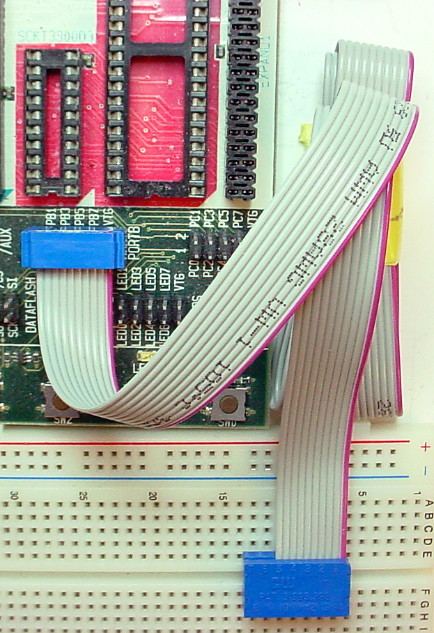
The Liquid Crystal Display (LCD):
A 16 character, two line (16x2), LCD display be used as a numerical display. The display we are using has an industry-standard interface. A more detailed data sheet for a similar display shows the command set, but start by reading the demo code, not by reading the data sheet. There are several aspects of the display you should note:
- Connecting the power backwards may destroy it.
Always check the polarity before connecting the display.
- The 14 pin header is on a corner of the display. LCD pin 1 is closest to the edge of the pc-board.
The connection pattern is shown below.
Note that pins 7 to 10 on the LCD are not connected and that MCU port pin C3 is not used.
| LCD pin |
Mega644 pin |
| 1 gnd |
gnd on STK500 |
| 2 Vcc |
VTG on STK500 |
| 3 contrast ** |
---------------> |
| 4 rs |
port C0 |
| 5 rd |
port C1 |
| 6 en |
port C2 |
| 7 n.c. |
-- |
| 8 n.c. |
-- |
| 9 n.c. |
-- |
| 10 n.c. |
-- |
| 11 |
port C4 |
| 12 |
port C5 |
| 13 |
port C6 |
| 14 |
port C7 |
** contrast is connected to the wiper (connection 2, see below) of a 10K trimpot.
Vcc goes to connection 1 and gnd to 3 of the trimpot.
Adjust the LCD contrast using a small screwdriver to turn the trimpot.
Trimpot schematic: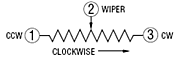
Trimpot bottom view: 
Trimpot image: 
Assignment
Timing of all functions in this lab, and every exercise in this course will be handled by interrupt-driven counters, not by software wait-loops. This will be enforced because wait-loops are hard to debug and tend to limit multitasking.
Write a C program which will:
- Wait for the user to push a button.
A message on the LCD will tell the user the system is ready.
- When the button is pushed the program will remove the ready message from the LCD,
wait for a random time between about 1.0 and 2.0 seconds,
then turn on an LED, produce a tone (around 1000 Hz), and start a timer.
If the user pushes a button before the LED is turned on, display a "CHEAT" message!
- When the user presses the same button again the timer will stop, the LED will extinguish, and the tone will stop.
The elapsed time since the LED was turned on will be displayed in millseconds on the LCD, along with the fastest time already recorded in eeprom.
If the user does not press a button within 1 second, display an appropriate message.
- When the user presses the same button again the system will go back to the ready state (1) above.
If the time just meaured is less than the time in eeprom, the value in eeprom is updated.
Initally, the eeprom will be set to 1000 milliseconds. I hope nobody is slower than that.
The eeprom value should persist through a power cycle.
When you demonstrate the program to
a staff member, you should demonstrate all the functions above.
Your program should not need to be
reset during the demo.
Your written lab report should include the sections mentioned in the policy page, and :
- What is your average reaction time?
- Is your reaction time faster watching the LED with no sound, or sound with no LED, or with both?
- A heavily commented listing of your code.
Copyright Cornell University January 3, 2012