You will construct a digital multimeter (DMM) capable of measuring voltage, resistance, and frequency. A keypad will be used to choose functions. An LCD will be used to indicate system state and measured levels.
Procedure:
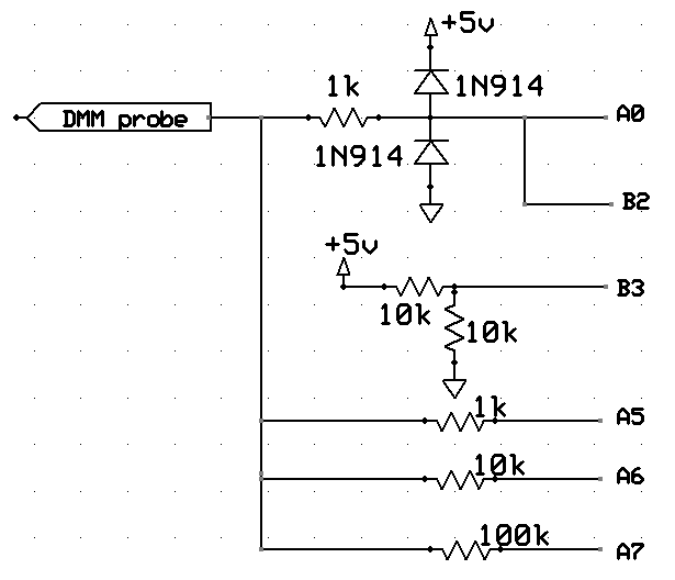
You will need to connect some circuitry to the Mega644 pins labeled on the right of the schematic below. The 1k resistor and diodes protect the analog input (A0) from over/under voltage. B2 is the input to the internal comparator, which will be used for frequency measurements. B3 is the reference pin for the comparator. The three decade resistors will be turned on (one at a time) to measure resistance. The tristate i/o pins make it very easy to connect a resistor to ground (output-low), Vcc (output-high), or disconnect (input-no pullup). You will autorange voltage by changing Vref internally, autorange frequency by changing the timer 1 prescalar, and autorange resistance by turning different resistors on. If we denote one of the three resistors as R (1k, 10k, 100k), and the resistor-under-test connected to the probe as Rt, then
Rt = R/(Vcc/Vin - 1) The sensitivity of the resistance measurement decreases as Vin increases, suggesting that you keep Rt<<R. However, low Vin means significant quantization error in the ADC. You will need to keep Vin between about 0.1*Vref and 0.9*Vref during resistance measurements to keep 5% accuracy.
The probe input goes to the ADC and internal comparator. This example (ADCtestGCC644.c uart.c, uart.h, project zip) shows how to set up the A/D converter to read a trimpot.
This example shows how to get higher ADC accuracy by putting the MCU to sleep during the conversion to cut down digital noise. Note that some special timing code has to be added to make the UART work correctly when you put the MCU to sleep.
In this lab, you are going to have to modify the ADC code to detect voltage and autorange the ADC.
A close reading of the 644 data sheet, Table 26-7, gives the V-reference impedance as 30 kohm. The STK500 schematic
http://people.ece.cornell.edu/land/courses/ece4760/AtmelStuff/STK500_Schematics.pdf indicates (pages 4 and 2) that 20 nF is placed from Aref to ground. This implies a time-constant to CHANGE Vref of
3e4 x 20e-9 = 60e-5 or 600 microseconds! This means that to get 8-bit accuracy after you change Vref, you must wait 1/256 = exp(-t/600) or t~3 mSec before doing another conversion!
You will need to get user input from a keypad with one of two following configurations. Some keypads have the connector on the top, as shown. Some have them on the bottom. A demonstration keypad scanning code for testing your connections is here. An example of a debounce state machine for a single STK500 pushbutton (not the keypad) is included here for reference.
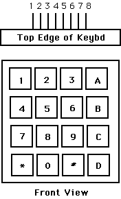
Connector:  top:8-pin      top:9-pin   bottom
Pin 1  ---- row 1 2 3 A    col 1       col 1
Pin 2  ---- row 4 5 6 B    col 2       col 2
Pin 3  ---- row 7 8 9 C    col 3       col 3
Pin 4  ---- row * 0 # D    col 4       col 4

Pin 5  ---- col 1 4 7 *    row 1       row 1
Pin 6  ---- col 2 5 8 0    row 2       row 2
Pin 7  ---- col 3 6 9 #    row 3       row 3
Pin 8  ---- col A B C D    row 4       row 4
Pin 9  ----              (NO CONNECT--common)

(a) Each switch shorts one row to one column.
(b) Each pin should be connected to one bit of an i/o port.
(c) The i/o port pins will be used both as inputs and outputs.
    When they are inputs, they should have active pullup resistors.
(d) On the 9-pin models, do not connect the common lead.


Hints on debugging are here.
If you decide to print floating point numbers using fprintf you need to follow the directions in Using sprintf function for float numbers in AVR-GCC the AVRstudio directions are at the bottom of the page,-Wl,-u,vfprintf -lprintf_flt switches.
An easier wayto print floats is to use the AVRLIBC stdlib function dtostrf as explained in AVRfreaks. An example.