Cornell University ECE4760
KeyPad using mcp23s17 Port Expander
Pi Pico rp2040/2350
The keypad to mcp23s17 description and wiring
The Microchip mcp23s17 port expander adds 16 lines of digital i/o, driven by an SPI connection to the Pico. The 16 lines are grouped into two 8-bit ports. Each i/o line may be set to input or output. Each i/o line may turn on an internal pullup resistor (there are no pulldowns), if it is an input. The grouping of lines into two 8-bit ports means that one spi transaction can affect the eight i/o lines of PortA or of PortB. You should refer to the port expander page for details.
For interfacing the keypad, we are going to use only PortA. Three bits will be set to be outputs, and five bits will be set to inputs, however only 4 inputs are actually used. The fifth one is pulled up so that it reliably reads high. Refer to the wiring summary for more information. The top 4 bits of PortA (inputs) are wired directly to connections 1 to 4 on the keypad (see below). The bits 1 to 3 are outputs and protected from each other by 470 ohm resistors.
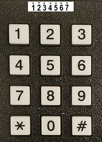
The line of numbers across the top of the image represents the seven connections on the underside of the keypad.
Each keypad button shorts one row-connector pin to one column-connector pin.
Keypad Connector        Port Expander
Pin 1 --- button row 1 (directly to pin 25, PortA bit 4)
Pin 2 --- button row 2 (directly to pin 26, PortA bit 5)
Pin 3 --- button row 3 (directly to pin 27, PortA bit 6)
Pin 4 --- button row 4 (directly to pin 28, PortA bit 7)

Pin 5 --- button col 1 (470 ohm resistor to pin 24, PortA bit 3)
Pin 6 --- button col 2 (470 ohm resistor to pin 23, PortA bit 2)
Pin 7 --- button col 3 (470 ohm resistor to pin 22, PortA bit 1)

Turn on port expander i/o port internal pullup resistors on all inputs.
Note that PortA bit 0 is not used, but must have the pullup turned on!
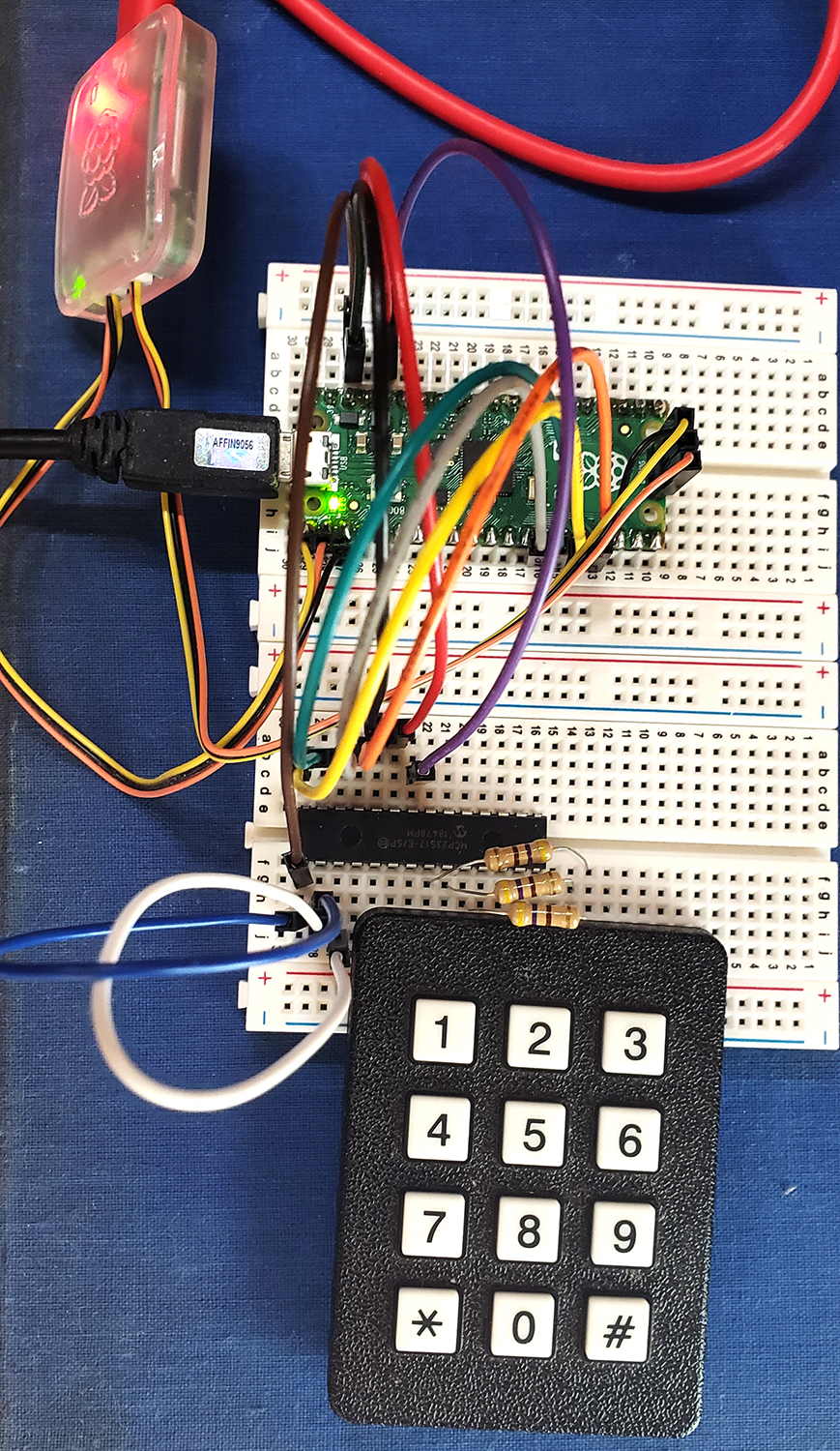
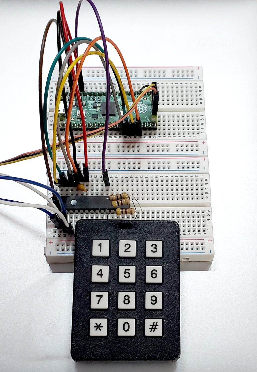
A couple of photos show the general layout, but the connection from the port expander to the keypad is hidden under the keypad.
Note the decoupling capacitor across Vdd and Vss.
Value is 0.1 μf.
The keypad scanner code
For every full scan of all the keys you sequential drop one of the output lines to zero, with the other two high, then read the four input bits for each of the three columns. If a button is pressed then one or more of the input lines will be low. If more than one is low in a column, then the user pushed two buttons in the same column, which is invalid.
If more than one button is pressed on each full scan (all three columns) then the press is invalid.
If there is exactly one button pushed, then the 7-bit pattern consisting of the 3-bit outputs to the keypad and 4-bit
inputs from the keypad is matched to a lookup table of 12 valid entries. The table converts the 7-bits of internal representtaion to a button number and label.
For example, if the zero-button is pushed then reading PortA yields 0xf7 for the left column, 0x7b for the middle column (with the pushed zero-button), and 0xfd for the right column. The left and right column upper digit values indicate no button push in those columns, since the top hex digit is all ones. The middle colunm value of 0b0111_1101 top bit indicates that the switch conected to PortA bit-7 is zero, while the lower four bits show that exactly one output bit is zero. The scan code 0x7b occupies the index=zero entry on the scan_to_digit table, so the algorithm returns a zero.
The demo code runs about 5 times/sec for debugging. In actual interactive use, you are going to strip out the printing from the thread, and run the thread at ~30/sec, while throwing a flag or semaphore telling a higher level routine (e,g, debouncer) that a button was pushed. The underside of the keypad has exposed connections. If you touch a connection, the port expnader seems to crash from ESD. To work aroung this, the code sets the direction and pullup registers for each full scan. Following the setup, each of the three output patterns is sent to the keypad, and PortA is read. Reading a port reads both the inputs and the output pins. If there is exactly one pressed button, the routine matches the scan code to the table and outputs the table index (button label) of the match. For testing the program also prints the raw scan-code.
Test code, mcp23s17 header, Project ZIP
Note that the build directory of the project must be regenerated.
Our security software does not like executables in ZIP files.
Copyright Cornell University July 11, 2025