Cornell University ECE4760
74hc595 shift register for more output
Pi Pico rp2040/2350
The 74hc595 description and wiring
The 74hc595 is an 8-bit shift register (SR) driven by an SPI TX-only connection to the Pico. The internal shifter is connected to 8 output pins using 8 D-flipflops. The last shift register stage has an extra (unlatched) output which can be daisy-chained to the serial input of another SR. This means that the Pico can control a very large number of outputs using just three pins as described below.
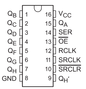
The 74hc595 we use is in 16-pin PDIP package as shown to the left.
QA to QH are the latched outputs. QH
'
is the direct shift register output for daisy-chaining to the next SR, if any.
The Pico SPI SCLK line is connected to the shift-register clock, SRCLK.
The Pico SPI TX line is connected to serial in, SER.
The D-flopflop output latch clock is RCLK.
Until RCLK is toggled high, the shift register just passes bits down the shifter. This allows
very long bit loads followed by synchronous output update.
I wired the output enable, OE, low (enabled) and
shift_clear, SRCLR, high (disabled)
The example test codes use two SRs to control 16 LEDs
The wiring details as a text table.
The image of the circuit is basically useless, but included for amusment and to show the LEDs.
Note that this circuit uses one 470 ohm resistor to limit current to eight LEDs.
For real applications where uniform brightness in important, you need one resistor per LED.
The SR command interface.
Adding
#include "74hc595_rp2040.h"
to your program adds the shift register code.
Functions:
- void SR_init(void)
Sets up the spi channel speed to the max for this chip, mode and i/o pins
Sets up and clears the output RCLK
- void SR_load(uint8_t * src, size_t len)
A pointer to the bits to be sent to the SRs and the length of the bit stream
MSB is sent first. The length parameter is measured in bytes.
If the pointer is an array name, then
index zero is sent first, followed up to the
length of the array in bytes specifed by the second parameter.
- void SR_latch(void)
Moves the current shift register contents to the output pins.
You would usually do this after all the bits are sent to load however many SRs are daisy-chained.
- void SR_clear(uint8_t pattern, int length)
Sets eight*length bits to the value of pattern, repeated every 8 bits.
Two patterns are used so much they have names.
ALL_ZEROS clears all of the outputs
ALL_ONES sets all of the outputs
The test code.
This program merely exercises the inteface routines to the SR interface to that you can test connections and see the syntax.
There are two threads running on one core. The usual blinky thread, of course, blinks. The serial thread:
- Sets up the SR, in this case two daisy-chained 74hc595.
Then force all 16 output pins to zero.
set up spi
SR_init();
clear any power up artifacts
SR_clear(ALL_ZEROS, 2);
- prompts for a 4-digit hexadecimal number and sends the number to the SR.
The high order bit of the 4 digits is shifted in first.
For example entering hexidecimal 8000
turns on the LED at the far end of the SR.
sscanf(pt_serial_in_buffer,"%2x%2x", &bit_vector[0], &bit_vector[1]) ;
load the shift reg using an spi channel -- parameters are a pointer to data and data length in bytes
SR_load(bit_vector, 2);
now latch the Shift Reg to its output pins
SR_latch();
- repeats from 2 above
Test Code, 74hc595_rp2040.h, Project ZIP, Simple Animation
Copyright Cornell University
July 17, 2025